-
#1
На этом сайте наконец то нашел руководство по ремонту Ямаха профессионал. www.moto-m0t0.ru .Там Ямахи за 2014 и 2016 год, но мне на ямаху 2012 года подошла. Могу отправить на электронную почту , Бесплатно!
-
#2
На проф 2 скинь если не сложно
-
#3
На проф 2 скинь если не сложно
К сожалению на профиль 2 не получается скачать
-
#4
На этом сайте наконец то нашел руководство по ремонту Ямаха профессионал. www.moto-m0t0.ru .Там Ямахи за 2014 и 2016 год, но мне на ямаху 2012 года подошла. Могу отправить на электронную почту , Бесплатно!
Доброго времени суток! Вы бы не могли мне помочь скинуть монуал по ремонту ямахи на мой ник? Буду очень Вам признателен!!!
-
#5
Доброго времени суток! Вы бы не могли мне помочь скинуть монуал по ремонту ямахи на мой ник? Буду очень Вам признателен!!!
На проф 2 скинь если не сложно
-
13,3 MB
Просмотры: 2.023
-
#6
На этом сайте наконец то нашел руководство по ремонту Ямаха профессионал. www.moto-m0t0.ru .Там Ямахи за 2014 и 2016 год, но мне на ямаху 2012 года подошла. Могу отправить на электронную почту , Бесплатно!
Скинь и мне пожалуйста setnorm@mail.ru
-
#7
Здра
На этом сайте наконец то нашел руководство по ремонту Ямаха профессионал. www.moto-m0t0.ru .Там Ямахи за 2014 и 2016 год, но мне на ямаху 2012 года подошла. Могу отправить на электронную почту , Бесплатно!
Здравствуйте, скиньте мне на электронку, если не сложно. Буду очень благодарен
-
#8
Здравствуйте, скиньте мне на электронку, если не сложно. Буду очень благодарен[/QUOTE]
Привет,пришли адрес электронной почты на этот номер,89140819413,я с Анадыря.
-
#9
Ватсап,Канчаланская группа,скинул туда.
-
#10
Огромное с
Ватсап,Канчаланская группа,скинул туда.
Огромное спасибо, как раз я там и живу. Как только появится интернет нормальный я сразу же скачаю
|
Title |
File Size |
Download Links |
|
Yamaha BR250 Bravo Snowmobile Service Manual.pdf |
10.3Mb |
Download |
|
Yamaha BR250 Parts Catalog.rar |
8.3Mb |
Download |
|
Yamaha BR250F Service Manual.pdf |
10.8Mb |
Download |
|
Yamaha BR250TG/VK540EG Owner’s Manual.pdf |
8.7Mb |
Download |
|
Yamaha EC340E Supplementary Service Manual.pdf |
892.9kb |
Download |
|
Yamaha ET300E Supplementary Service Manual.pdf |
790.2kb |
Download |
|
Yamaha ET410 Parts Catalog.rar |
4.1Mb |
Download |
|
Yamaha FX Nytro Owner`s Manual.rar |
18.5Mb |
Download |
|
Yamaha FX Nytro Service Manual.pdf |
13.5Mb |
Download |
|
Yamaha FX/FX10/RFX10 Owner’s Manual.rar |
32Mb |
Download |
|
Yamaha FX10 Parts Catalog.rar |
13.2Mb |
Download |
|
Yamaha MM600/MM700 Parts Catalog.rar |
6.2Mb |
Download |
|
Yamaha MM600/MM700/MX600/VT600/VT700/VX600/VX700 Owner`s Manual.rar |
32Mb |
Download |
|
Yamaha MM700/VT700/VX700ER Owner`s Manual.pdf |
9.2Mb |
Download |
|
Yamaha Phazer Venture Lite PZ50MTA 2011 Supplementary Service Manual.pdf |
6.4Mb |
Download |
|
Yamaha PZ-series Parts Catalog.rar |
30Mb |
Download |
|
Yamaha PZ50 Owner`s Manual.rar |
11.7Mb |
Download |
|
Yamaha PZ50 Phazer, Venture Owner`s Manual.rar |
21.6Mb |
Download |
|
Yamaha PZ50 Service Manual.rar |
21.2Mb |
Download |
|
Yamaha PZ500/VT500 Owner`s Manual.pdf |
2.4Mb |
Download |
|
Yamaha PZ500C/VT500XLC Service Manual.rar |
6Mb |
Download |
|
Yamaha RS10/RS90/RSG90/RST90 Owner`s Manual.rar |
31Mb |
Download |
|
Yamaha RS90 Parts Catalog.rar |
7.6Mb |
Download |
|
Yamaha RS90/RSG90/RST90 RS Vector, RS Venture Owner`s Manual.rar |
63.5Mb |
Download |
|
Yamaha RS90/RSG90/RST90 RS Venture Service Manual.rar |
37.1Mb |
Download |
|
Yamaha RS90L Owner`s Manual.pdf |
5.8Mb |
Download |
|
Yamaha RSG90 Parts Catalog.rar |
3.5Mb |
Download |
|
Yamaha RST90 Parts Catalog.rar |
11.9Mb |
Download |
|
Yamaha RX-1 Service Manual.pdf |
18.8Mb |
Download |
|
Yamaha RX10 Parts Catalog.rar |
28Mb |
Download |
|
Yamaha RX10/RXW10 Owner`s Manual.rar |
28.6Mb |
Download |
|
Yamaha RX10LTGTYL Service Manual.pdf |
32.7Mb |
Download |
|
Yamaha RX90/RXW90 Apex Owner`s Manual.rar |
48.2Mb |
Download |
|
Yamaha RXW10 Parts Catalog.rar |
5.1Mb |
Download |
|
Yamaha SL292C 1971 Service Manual.pdf |
26Mb |
Download |
|
Yamaha Snowmobile Design Description.pdf |
6.9Mb |
Download |
|
Yamaha snowmobile fault codes list.rar |
1.7Mb |
Download |
|
Yamaha SRX700 Parts Catalog.rar |
5.9Mb |
Download |
|
Yamaha SRX700 Service Manual.pdf |
7.4Mb |
Download |
|
Yamaha SX500/600/700 Parts Catalog.rar |
10.7Mb |
Download |
|
Yamaha SXV-VT owner`s manual.rar |
48.3Mb |
Download |
|
Yamaha SXV60/SXV70/VT60/VT70 Owner`s Manual.rar |
48.3Mb |
Download |
|
Yamaha SXV70 Parts Catalog.rar |
14.6Mb |
Download |
|
Yamaha SXV70ERJ Owner’s Manual.pdf |
9.6Mb |
Download |
|
Yamaha VK10/VK10D RS Viking Owner`s Manual.rar |
15.6Mb |
Download |
|
Yamaha VK10/VK540 Parts Catalog.rar |
22.7Mb |
Download |
|
Yamaha VK10L/ Yamaha VK10X Owner`s Manual.rar |
7.9Mb |
Download |
|
Yamaha VK540EG/VK540EK Owner`s Manual.rar |
4.8Mb |
Download |
|
Yamaha VK540EK Service Manual.pdf |
4.9Mb |
Download |
|
Yamaha VT Parts Catalog.rar |
65.9Mb |
Download |
|
Yamaha VT500XL Owner`s Manual.pdf |
8.2Mb |
Download |
|
Yamaha VT700F Service Manual.pdf |
13.1Mb |
Download |
|
Yamaha VX500/600/700 Parts Catalog.rar |
21.2Mb |
Download |
|
Yamaha VX500SXBC Service Manual.pdf |
2.3Mb |
Download |
Yamaha is one of the oldest corporations in the world producing musical instruments, sound equipment, sports equipment, etc.
Yamaha began to produce snowmobiles from the beginning of the 60s of the last century, and already in 1968 the mass production of this equipment began. The company’s products were oriented to the
US and Canada markets.
A feature of Yamaha snowmobiles is that their motor was borrowed from motorcycles, due to this, snowmobiles received additional aggression. Every year, Yamaha increased
production, and by 1983, 500 thousand units of equipment had rolled off its conveyors, and by 1997, the line of one million snowmobiles had been overcome.
Production facilities are located in both Japan and the United States. Yamaha is considered the most successful manufacturer of snowmobiles, if we consider their financial performance. The
Japanese manufacturer worldwide employs more than 40 thousand employees. The domestic market of Japan in the total share of sales occupies only 12%, the remaining 88% is export.
The modern market divides snowmobiles into:
- Utilitarian;
- Tourist;
- Sports;
- Mountain.
Japanese utilitarian Yamaha snowmobiles are very popular in Russia. Especially Yamaha RS Viking Professional and Yamaha VK 540. This is a classic of the genre. If you need a
reliable utilitarian snowmobile, the first thing that comes to mind is, of course, Viking.
The latest VK540 IV has even greater cross-country ability in deep snow, carrying capacity, high-torque and endurance. At the same time, it is economical and highly reliable.
Everything in VK540 IV is aimed at giving you maximum pleasure from overcoming the virgin snow. The heart of the snowmobile is the time-tested 535cc 2-cylinder 2-stroke Yamaha engine, powerful
and tough. It is reliable and easy to maintain, and in combination with a 2-speed transmission expands the capabilities of the snowmobile. Innovatively designed wide skis with an optimized skate
profile provide excellent deep snow maneuverability and handling.
Lightweight and durable, the wide Camoplast Ripsaw Full Block ™ caterpillar is known for its exceptional cross-country ability. A new torsion rear suspension was used, leading drive wheels of the
track with external gearing. Electric heating of the handlebars of the steering wheel and the trigger of «gas», a high windshield were installed. Convenient seatpost and spacious trunk, 2-seater
seat, spacious footrests with non-slip surface. With VK540IV, work has never been so much fun!
Yamaha Japanese snowmobiles are always among the best in the world. In the 2011 lineup, 3 models were presented:
- Snowmobile Yamaha RS Venture TF
- Snowmobile Yamaha RS Venture GT
- Snowmobile Yamaha Venture Multi Purpose
Yamaha sports snowmobiles in 2011 were represented by only three models: FX Nytro R-TX, FX Nytro X-TX and APEX X-TX. All these models are suitable for fast driving along natural
trails and are of the rough trail type. It is important to recall that all of these models are 4-stroke. This is the general policy of Yamaha on environmentally friendly technology. Let us focus
on the new product of 2011 for the Russian market — the Yamaha APEX X-TX model. This is the first snowmobile to feature an EPS electric power steering system that sets new standards for handling
and stability. This model is equipped with a modified four-cylinder engine with an EXUP exhaust system and a fuel injection system. These improvements were made in order to significantly increase
peak power and torque at low and medium ranges of engine speed. A long 144 ”/ 3658mm track, new front suspension geometry, Dual Shock® suspensions and wide skis make it easy to cross any trails.

- Manuals
- Brands
- Yamaha Manuals
- Snowmobiles
- VK10W
- Supplementary service manual
-
Contents
-
Table of Contents
-
Troubleshooting
-
Bookmarks
Quick Links
SUPPLEMENTARY SERVICE MANUAL
VK10W
LIT-12618-02-57
8GS-28197-10
Related Manuals for Yamaha VK10W
Summary of Contents for Yamaha VK10W
-
Page 1
SUPPLEMENTARY SERVICE MANUAL VK10W LIT-12618-02-57 8GS-28197-10… -
Page 2
FOREWORD This Supplementary Service Manual has been prepared to introduce new service and new data for the VK10W. For complete information, on service procedures, it is necessary to use this Supple- mentary Service Manual together with following manual: RS90K, RS90RK, RSG90K, RS90MK, RST90K, RST90TFK SERVICE MANUAL:… -
Page 3: How To Use This Manual
If there is any question about a service procedure, it is imperative that you contact a Yamaha dealer for any service information changes that apply to this model. This policy is intended to provide the customer with the most satisfaction from his vehicle and to conform to federal environmental quality objectives.
-
Page 4: Chassis
ILLUSTRATED SYMBOLS (Refer to the illustration) INSP INFO Illustrated symbols 1 to 9 are designed as thumb tabs to indicate the chapter’s number and content. 1 General information 2 Periodic inspection and adjustment POWR 3 Chassis CHAS 4 Power train 5 Engine 6 Cooling system 7 Carburetion…
-
Page 5
INDEX GENERAL INFORMATION INFO PERIODIC INSPECTION AND INSP ADJUSTMENT CHASSIS CHAS POWER TRAIN POWR ENGINE COOLING SYSTEM COOL CARBURETION CARB – ELECTRICAL ELEC SPECIFICATIONS SPEC… -
Page 6: Table Of Contents
GENERAL INFORMATION ENGINE SPECIAL TOOLS ……….1 CAMSHAFTS…………. 38 FOR ELECTRICAL SERVICE ……1 INSTALLATION……….38 PERIODIC INSPECTION AND CARBURETION ADJUSTMENT CARBURETORS ……….43 THROTTLE POSITION SENSOR (T.P.S.) INTRODUCTION………..2 INSPECTION AND ADJUSTMENT ….. 44 PERIODIC MAINTENANCE CHART FOR THE EMISSION CONTROL SYSTEM….2 ELECTRICAL GENERAL MAINTENANCE AND LUBRICATION CHART……..3…
-
Page 7: General Information
SPECIAL TOOLS INFO GENERAL INFORMATION SPECIAL TOOLS Some special tools are necessary for a completely accurate tune-up and assembly. Using the correct special tool will help prevent damage that can be caused by the use of improper tools or improvised techniques. NOTE: •…
-
Page 8: Periodic Inspection And Adjustment
INTRODUCTION/PERIODIC MAINTENANCE CHART FOR INSP THE EMISSION CONTROL SYSTEM PERIODIC INSPECTION AND ADJUSTMENT INTRODUCTION This chapter includes all information necessary to perform recommended inspections and adjustments. These preventive maintenance procedures, if followed, will ensure more reliable machine operation and a longer ser- vice life.
-
Page 9: General Maintenance And Lubrication Chart
INSP GENERAL MAINTENANCE AND LUBRICATION CHART GENERAL MAINTENANCE AND LUBRICATION CHART Every Initial Pre-opera- 1 month or Seasonally Item Remarks tion check 800 km or 4,000 km (Daily) (500 mi) (2,500 mi) (40 hr) (200 hr) Check oil level. Engine oil Replace.
-
Page 10
INSP GENERAL MAINTENANCE AND LUBRICATION CHART Every Initial Pre-opera- 1 month or Seasonally Item Remarks tion check 800 km or 4,000 km (Daily) (500 mi) (2,500 mi) (40 hr) (200 hr) Steering column bearing Lubricate with specified grease. Ski and front suspension Lubricate with specified grease. -
Page 11: Power Train
INSP DRIVE V-BELT POWER TRAIN DRIVE V-BELT WARNING When installing the new V-belt, make sure that it is positioned from 1.5 mm (0.06 in) above the edge of the secondary sheave to –0.5 mm (–0.02 in) below the edge a. If the V-belt is not positioned correctly, the clutch engagement speed will be changed.
-
Page 12
INSP DRIVE V-BELT 2. Adjust the position of the V-belt by removing or adding a spacer 1 on each adjusting bolt 2. V-belt position Adjustment More than 1.5 mm (0.06 in) above the Remove a spacer edge From 1.5 mm (0.06 in) above the edge to Not necessary –0.5 mm (–0.02 in) -
Page 13: Brake Pad Inspection
DRIVE V-BELT/BRAKE PAD INSPECTION/ INSP AIR BLEEDING (HYDRAULIC BRAKE SYSTEM) 6. Measure: • Drive V-belt circumference a Out of specification → Replace. V-belt circumference: 1,132 ~ 1,138 mm (44.6 ~ 44.8 in) BRAKE PAD INSPECTION 1. Apply the brake lever. 2.
-
Page 14: Drive Chain
AIR BLEEDING (HYDRAULIC BRAKE SYSTEM)/ INSP DRIVE CHAIN i. Repeat steps (e) to (h) until all of the air bubbles have disappeared from the fluid. j. Tighten the bleed screws. Bleed screw: 6 Nm (0.6 m · kg, 4.3 ft · lb) NOTE: If bleeding is difficult, it may be necessary to let the brake fluid settle for a few hours.
-
Page 15
INSP DRIVE CHAIN Checking steps: • Remove the rubber cap 1. • Check the oil level through the check window 2 located on the drive chain housing. • If the oil is below the minimum level mark a, remove the dipstick 3 and add sufficient oil to the maximum level mark b. -
Page 16
INSP DRIVE CHAIN Oil replacement Oil replacement steps: • Place the oil pan under the drain hole. • Remove the oil drain bolt (along with the gas- ket) 1 and drain the oil. CAUTION: Be sure to remove any oil from the heat protec- tor. -
Page 17: Tuning
INSP CLUTCH TUNING CLUTCH L Blue P Pink High altitude W White Y Yellow Specifications ~ 800 m 600 ~ 1,400 m 1,200 ~ 2,000 m 1,800 ~ 2,600 m 2,400 ~ 3,000 m È Elevation (~ 2,500 ft) (2,000 ~ 4,500 ft) (4,000 ~ 6,500 ft) (6,000 ~ 8,500 ft) (8,000 ~ 10,000 ft)
-
Page 18: Gear Selection
INSP CLUTCH/GEAR SELECTION The clutch may require tuning depending upon where the machine will be operated and the desired handling characteristics. The clutch can be tuned by changing the engagement and shifting speeds. Clutch engagement speed is defined as the engine speed at which the machine first begins to move from a complete stop.
-
Page 19
INSP GEAR SELECTION 1 Chain and sprocket part number È Parts name É Teeth & links Ê Parts no. Ë Standard 19 teeth 8FA-17682-90 20 teeth 8FA-17682-00 21 teeth 8FA-17682-10 Ì Drive sprocket 22 teeth 8FA-17682-20 23 teeth 8FA-17682-30 24 teeth 8FA-17682-40 38 teeth 8FB-47587-80… -
Page 20
INSP GEAR SELECTION 4 Secondary spring twist angle È Seat É Sheave 10° 40° 70° 100° 20° 50° 80° 110° 30° 60° 90° 120° 5 Torque cam (secondary spring seat) É Effects Ê Part no. Ë Cam angle Ì Identification mark Í… -
Page 21
INSP GEAR SELECTION 6 Primary spring Ì Spring rate Ð Outside Í Preload Ï Wire gauge Ò Free length Ë Parts No. Î Color Ñ No. of coils Ó Standard N/mm diameter N (kg) mm (in) mm (in) (kg/mm) mm (in) 90501-550A2 19.6 (2.00) 196 (20) -
Page 22
INSP GEAR SELECTION 7 Clutch weight É Weight g (oz) È Parts No. Ê Shape & ID mark Ë Standard without bush and rivets 8BU-17605-20 45.41 (1.603) 8CH-17605-10 35.32 (1.246) 8DG-17605-00 34.26 (1.208) 8DJ-17605-00 37.77 (1.332) 8DN-17605-10 39.76 (1.402) 8ES-17605-00 54.63 (1.928) 8FA-17605-10 63.81 (2.251) -
Page 23
INSP GEAR SELECTION 8 Weight rivets Ê Length Ë Weight È Parts No. É Material Ì Standard Í Effects mm (in) g (oz) √ (OUT) Î Increased force 90261-06033 Steel 17.2 (0.677) 4.5 (0.159) 90261-06034 Steel 13.9 (0.547) 3.6 (0.127) √… -
Page 24: High Altitude Tuning
INSP HIGH ALTITUDE TUNING HIGH ALTITUDE TUNING To attain the best performance in high altitude conditions, carefully tune the snowmobile as outlined below. Check STD settings • Carburetors • Spark plugs Adjust the main jet size according to the chart Test the main jet Adjust the size of the main jet Not OK…
-
Page 25: Power Train
POWR SHIFT LEVER POWER TRAIN SHIFT LEVER È: kg, 7.2 ft 10 Nm (1.0 m • • É: É 23 Nm (2.3 m kg, 17 ft • • É È É Q’ty Remarks Order Job name/Part name Shift lever assembly removal Remove the parts in the order listed below.
-
Page 26
POWR SHIFT LEVER È: kg, 17 ft 23 Nm (2.3 m • • É: 59 Nm (5.9 m kg, 43 ft • • È È É Q’ty Remarks Order Job name/Part name Shift lever disassembly Remove the parts in the order listed below. Shift lever stay Circlip Bearing… -
Page 27: Installation
POWR SHIFT LEVER INSTALLATION 1. Install: • Shift lever 1 • Shift lever stopper 2 • Shift guide 3 • Shift lever pin 4 • Spring Installation steps: • Install the shift lever 1 onto the shift lever stop- per 2. •…
-
Page 28: Drive Chain Housing
POWR DRIVE CHAIN HOUSING DRIVE CHAIN HOUSING Ï: È: Ì: kg, 4.3 ft kg, 13 ft kg, 31 ft 6 Nm (0.6 m 18 Nm (1.8 m 43 Nm (4.3 m • • • • • • Ð: É: Í: kg, 7.2 ft kg, 14 ft 55 Nm (5.5 m…
-
Page 29
POWR DRIVE CHAIN HOUSING È: Ì: Ï: kg, 4.3 ft kg, 13 ft kg, 31 ft 6 Nm (0.6 m 18 Nm (1.8 m 43 Nm (4.3 m • • • • • • Ð: É: Í: kg, 7.2 ft kg, 14 ft kg, 40 ft 10 Nm (1.0 m… -
Page 30
POWR DRIVE CHAIN HOUSING È: Ì: Ï: kg, 4.3 ft kg, 13 ft kg, 31 ft 6 Nm (0.6 m 18 Nm (1.8 m 43 Nm (4.3 m • • • • • • Ð: É: Í: kg, 7.2 ft kg, 14 ft kg, 40 ft 10 Nm (1.0 m… -
Page 31: Removal
POWR DRIVE CHAIN HOUSING REMOVAL 1. Remove: • Driven gear 1 NOTE: While holding the front axle assembly with spanner wrench 2, loosen the reverse driven gear bolt. INSPECTION 1. Inspect: • Drive chain housing • Drive chain housing cover Cracks/damage →…
-
Page 32
POWR DRIVE CHAIN HOUSING 2. Inspect: • Drive sprocket • Driven sprocket • Driven gear • Reverse drive gear • Counter gear • Low pinion gear • Low wheel gear • Low drive gear • Journal • Chain tensioner Pitting/wear/damage → Replace. •… -
Page 33: Installation
POWR DRIVE CHAIN HOUSING 5. Measure: • Brake disc thickness a Measure the brake disc thickness 1 ~ 3 mm (0.04 ~ 0.12 in) from the edge of the brake disc. Out of specification → Replace. Minimum thickness: 3.5 mm (0.14 in) INSTALLATION 1.
-
Page 34
POWR DRIVE CHAIN HOUSING Ó 0 ~ 1 mm (0 ~ 0.039 in) 3. Install: • Shift rod lock washer 1 NOTE: Bend a lock washer tab along a flat side of the bolt. 4. Adjust: • Shift rod length a Adjustment steps: •… -
Page 35: Secondary Shaft
POWR SECONDARY SHAFT SECONDARY SHAFT SECONDARY SHAFT AND DRIVE CHAIN HOUSING INSTALLATION 1. Install: • Secondary shaft È • Drive chain housing Installation steps: • Install the secondary shaft. • Tighten the bolt. Secondary shaft bolt: 30 Nm (3.0 m · kg, 22 ft · lb) •…
-
Page 36
POWR SECONDARY SHAFT 2. Measure: • Brake disc clearance a Out of the specification → Adjust. Brake disc clearance: 0.2 ~ 0.7 mm (0.008 ~ 0.028 in) 3. Adjust: • Brake disc clearance Adjustment steps: • Remove the circlip 8. •… -
Page 37: Brake
POWR BRAKE BRAKE È: kg, 4.3 ft 6 Nm (0.6 m • • É: kg, 13 ft 18 Nm (1.8 m • • Ê: kg, 35 ft 48 Nm (4.8 m • • È Ê È É Q’ty Remarks Order Job name/Part name Brake pad removal Remove the parts in the order listed below.
-
Page 38: Brake Pad Replacement
POWR BRAKE CAUTION: Disc brake components rarely require disas- sembly. DO NOT: • Do not disassemble components unless absolutely necessary. • Do not use solvents on internal brake compo- nents. • Do not use contaminated brake fluid for cleaning. • Use only clean brake fluid. •…
-
Page 39
POWR BRAKE 2. Install: • Brake pads • Pad spring Installation steps: • Connect a suitable hoses 1 tightly to the cali- per bleed screws 2. Put the other end of this hose into an open container. • Loosen the caliper bleed screws and push the pistons into the caliper with your finger. -
Page 40
POWR BRAKE Q’ty Remarks Order Job name/Part name Brake caliper and parking brake Remove the parts in the order listed below. removal Brake fluid Drain. Brake hose Brake caliper assembly Parking brake cable Spring Parking brake assembly Collar For installation, reverse the removal proce- dure. -
Page 41
POWR BRAKE È: 6 Nm (0.6 m kg, 4.3 ft • • É: 18 Nm (1.8 m kg, 13 ft • • È È É Q’ty Remarks Order Job name/Part name Brake caliper disassembly Remove the parts in the order listed below. Cap bolt Retaining pin Pad spring… -
Page 42: Brake Caliper Disassembly
POWR BRAKE BRAKE CALIPER DISASSEMBLY NOTE: Before disassembling a caliper, drain brake fluid from brake hose, master cylinder, brake caliper and brake reservoir of their brake fluid. 1. Remove: • Pistons • Piston seals 1 Removal steps: • Using a wood of piece 2, lock the right piston. •…
-
Page 43: Front Axle And Track
POWR FRONT AXLE AND TRACK FRONT AXLE AND TRACK 103.5 mm 121.5 mm 121.5 mm 103.5 mm (4.07 in) (4.78 in) (4.78 in) (4.07 in) INSTALLATION 1. Install: • Sprocket wheels • Guide wheels NOTE: • When pressing the sprocket wheels onto the front 32.5 mm 42 mm 58.5 mm…
-
Page 44: Engine
CAMSHAFTS ENGINE CAMSHAFTS INSTALLATION 1. Install: • Exhaust camshaft sprocket 1 • Intake camshaft sprocket 2 (with the special tool 3) Rotor holding tool: 90890-01235, YU-01235 • Camshaft sprocket bolts Camshaft sprocket bolt: 24 Nm (2.4 m · kg, 17 ft · lb) NOTE: Make sure that the holes a in the cylinder #3 cam and marks b and c on the camshaft sprockets are…
-
Page 45
CAMSHAFTS 2. Install: • Exhaust camshaft 1 • Intake camshaft 2 (with the camshaft sprockets) Installation steps: • Turn the crankshaft clockwise. • When piston #3 is at TDC on the compression stroke, align the “I” mark a on the A.C. mag- neto rotor with the stationary pointer b on the A.C. -
Page 46
CAMSHAFTS 3. Install: • Dowel pins • Intake camshaft caps • Exhaust camshaft caps NOTE: • The “I” mark refers to the intake camshaft caps and the “E” mark refers to the exhaust camshaft cap. • Install the camshaft caps with the arrow mark a pointing towards the right side of the engine. -
Page 47
CAMSHAFTS 5. Install: • Timing chain tensioner Installation steps: • While lightly pressing the timing chain tensioner rod by hand, turn the tensioner rod fully clock- wise with a thin screwdriver 1. NOTE: Make sure that the tensioner rod has been fully set clockwise. -
Page 48
® • Apply Sealant (Quick Gasket ) or Yamaha bond No. 1215 2 onto the mating surfaces of the cylin- der head cover gasket and cylinder head. • Tighten the cylinder head cover bolts stages and… -
Page 49: Carburetion
CARB CARBURETORS CARBURETION CARBURETORS Q’ty Remarks Order Job name/Part name Carburetor separation Remove the parts in the order listed below. Sub-wire harness 3 Carburetor heating hose Fuel delivery hose Float chamber air vent hose Vacuum hose Spring Starter plunger link Connecting bolt Throttle position sensor Carburetor…
-
Page 50: Throttle Position Sensor (T
CARB CARBURETORS THROTTLE POSITION SENSOR (T.P.S.) INSPECTION AND ADJUSTMENT NOTE: Before adjusting the throttle position sensor, prop- erly adjust the idle speed. 1. Inspect: • Throttle position sensor Inspection steps: • Disconnect the throttle position sensor coupler. • Connect the pocket tester (Ω × 1k) to the throt- tle position sensor coupler.
-
Page 51
CARB CARBURETORS 2. Adjust: • Throttle position sensor angle Adjustment steps: • Disconnect the throttle position sensor coupler. • Connect the test coupler to the throttle position sensor. • Connect three dry cells (1.5 V × 3 pcs.) in series to the test coupler. -
Page 52: Electrical
– ELEC SIGNAL SYSTEM ELECTRICAL…
-
Page 53: Circuit Diagram
– ELEC SIGNAL SYSTEM SIGNAL SYSTEM CIRCUIT DIAGRAM 2 A.C. magneto 3 Rectifier/regulator 4 Main switch 5 Load control relay 6 Main fuse 9 Battery I Ignitor unit M Coolant temperature sensor P Frame ground T DC back buzzer U Gear position switch relay V Gear position switch W Brake light switch X Tail/brake light…
-
Page 54: Troubleshooting
– ELEC SIGNAL SYSTEM TROUBLESHOOTING BACK BUZZER DOES NOT SOUND. Check the signal fuse. FAULTY Replace the signal fuse. Check the battery. OUT OF SPECIFICATION Replace and/or charge the battery. Check the stator coil. OUT OF SPECIFICATION Replace the stator coil assembly. Check the main switch.
-
Page 55: Gear Position Switch
– ELEC SIGNAL SYSTEM GEAR POSITION SWITCH 1. Check: • Gear position switch 1 continuity Faulty → Replace. – Shift lever position Continuity DRIVE (D) or LOW (L) REVERSE GEAR POSITION SWITCH RELAY 1. Inspect: • Gear position switch relay 1 Inspection steps: •…
-
Page 56: Specifications
SPEC GENERAL SPECIFICATIONS SPECIFICATIONS GENERAL SPECIFICATIONS Model VK10W Model code number: 8GS1 (USA/Canada) 8GS2 (Europe) Dimensions: Overall length 3,270 mm (128.7 in) Overall width 1,200 mm (47.2 in) Overall height 1,380 mm (54.3 in) Weight: Dry weight 360 kg (794 lb)
-
Page 57
SPEC GENERAL SPECIFICATIONS Model VK10W Spark plug: Type NGK R CR8E Manufacture 0.7 ~ 0.8 mm (0.028 ~ 0.031 in) Transmission: Primary reduction system V-Belt Primary reduction ratio 3.8 ~ 1 : 1 Clutch type Automatic centrifugal engagement Secondary reduction system… -
Page 58: Maintenance Specifications
SPEC MAINTENANCE SPECIFICATIONS MAINTENANCE SPECIFICATIONS ENGINE Model VK10W Cylinder head: Volume (with spark plug) 22.82 ~ 23.62 cm (1.39 ~ 1.44 cu.in) <Warpage limit> 0.10 mm (0.0039 in) Lines indicate straight edge measurement. Cylinder: Material Aluminum alloy with dispersion coating Bore size 79.000 ~ 79.010 mm (3.1102 ~ 3.1106 in)
-
Page 59
SPEC MAINTENANCE SPECIFICATIONS Model VK10W Valves, valve seats, valve guides: Valve clearance (cold) Intake 0.15 ~ 0.22 mm (0.0059 ~ 0.0087 in) Exhaust 0.21 ~ 0.25 mm (0.0083 ~ 0.0098 in) Valve dimensions Valve head diameter A Intake 29.9 ~ 30.1 mm (1.1771 ~ 1.1850 in) Exhaust 25.9 ~ 26.1 mm (1.0197 ~ 1.0276 in) -
Page 60
SPEC MAINTENANCE SPECIFICATIONS Model VK10W Valve spring: Free length Intake 39.73 mm (1.56 in) <Limit> 37.74 mm (1.48 in) Exhaust 39.73 mm (1.56 in) <Limit> 37.74 mm (1.48 in) Installed length (valve closed) Intake 33.0 mm (1.30 in) Exhaust 33.0 mm (1.30 in) -
Page 61
SPEC MAINTENANCE SPECIFICATIONS Model VK10W Piston ring: Sectional sketch Top ring Ring type Barrel Dimensions (B × T) 1.00 × 2.80 mm (0.039 × 0.110 in) 2nd ring Ring type Taper Dimensions (B × T) 1.00 × 2.90 mm (0.039 × 0.114 in) Oil ring Dimensions (B ×… -
Page 62: Cooling System
SPEC MAINTENANCE SPECIFICATIONS Model VK10W Carburetor: Type/Quantity CVK40/3 Manufacturer KEIHIN I.D. mark 8ES1 02 Main jet (M.J) #148 Main air jet (M.A.J) Jet needle (J.N) N425-BSJ00 Needle jet (N.J) W9554-26538#6 Pilot jet (P.J) Pilot air jet (P.A.J) #120 Pilot outlet (P.O)
-
Page 63: Power Train
SPEC MAINTENANCE SPECIFICATIONS POWER TRAIN Model VK10W Transmission: Type V-belt automatic Range of ratio 3.8 ~ 1.0 : 1 Engagement speed r/min 2,200 ~ 2,600 r/min Shift r/min 8,250 ~ 8,750 r/min Sheave distance 267 ~ 270 mm (10.51 ~ 10.63 in) Sheave offset 13.5 ~ 16.5 mm (0.53 ~ 0.65 in)
-
Page 64
SPEC MAINTENANCE SPECIFICATIONS Model VK10W Hole position Sheave side-spring side (twist angle) 3-3 (60°) Spring rate 12.3 N/mm (1.25 kg/mm, 70.23 lb/in) Number of coils 5.53 Free length 75 mm (2.95 in) Torque cam angle 39° Drive chain: Type Borg Warner Automotive 23RH303-68ASM… -
Page 65
SPEC MAINTENANCE SPECIFICATIONS Model VK10W Shock absorber: Damping force Front Extension 540 N/0.3 m/s (55.1 kg/0.3 m/s, 121.4 lb/0.3 m/s) Compression 1,130 N/0.3 m/s (115.2 kg/0.3 m/s, 254.0 lb/0.3 m/s) Rear Extension 2,530 N/0.3 m/s (258.0 kg/0.3 m/s, 568.7 lb/0.3 m/s) Compression 690 N/0.3 m/s (70.4 kg/0.3 m/s, 155.1 lb/0.3 m/s) -
Page 66: Chassis
SPEC MAINTENANCE SPECIFICATIONS CHASSIS Model VK10W Frame: Frame material Monocoque (Aluminum & Steel) Seat height 716 mm (28.2 in) Luggage box location Under seat Steering: Lock-to-lock angle (left) 29.7° (R ski) 34.4° (L ski) (right) 34.4° (R ski) 29.7° (L ski)
-
Page 67: Electrical
SPEC MAINTENANCE SPECIFICATIONS ELECTRICAL Model VK10W Voltage 12 V Ignition system: Ignition timing (B.T.D.C.) 5° at 1,400 r/min Advanced type Digital type Ignition coil: Model/Manufacturer F6T558/MITSUBISHI Ignition spark gap 6.0 mm (0.24 in) 1.19 ~ 1.61 Ω at 20 °C (68 °F)
-
Page 68
SPEC MAINTENANCE SPECIFICATIONS Model VK10W T.P.S. (throttle position sensor): Manufacturer KEIHIN Resistance 4 ~ 6 kΩ at 20 °C (68 °F) (Blue – Black) 0 ~ 4 kΩ at 20 °C (68 °F) (Yellow – Black) Oil level switch: Model/Manufacturer… -
Page 69
SPEC MAINTENANCE SPECIFICATIONS Model VK10W Speed sensor: Model/Manufacture 8EK/NIPPON SEIKI Carburetor heater: Model/Manufacture 5FU/NIPPON THERMOSTAT Wattage 30 W 6 ~ 10 Ω at 20 °C (68 °F) Resistance… -
Page 70: High Altitude Settings
SPEC MAINTENANCE SPECIFICATIONS HIGH ALTITUDE SETTINGS Temperature –30 °C –10 °C 10 °C (–22 °F) (–14 °F) (50 °F) Altitude Idling speed (r/min) 0 ~ 200 m #150 #148 #148 1,400 (0 ~ 700 ft) 200 ~ 1,500 m #148 #148 #145 1,400…
-
Page 71
SPEC MAINTENANCE SPECIFICATIONS… -
Page 72: Tightening Torque
SPEC TIGHTENING TORQUE TIGHTENING TORQUE ENGINE Tightening torque Parts to be tightened Remarks m · kg ft · lb Spark plug Cylinder head bolt (M10 × 1.25) See NOTE. Cylinder head bolt Camshaft cap and cylinder head Apply the engine oil. Cylinder head cover Camshaft and camshaft sprocket Timing chain tensioner…
-
Page 73
SPEC TIGHTENING TORQUE Tightening torque Parts to be tightened Remarks m · kg ft · lb Primary sheave drive shaft assembly bolt Connecting rod and cap See NOTE. Balancer ® Balancer shaft bearing retainer Apply LOCTITE A.C. magneto rotor Apply the engine oil. A.C. -
Page 74: Power Train
SPEC TIGHTENING TORQUE POWER TRAIN Tightening torque Parts to be tightened Remarks m · kg ft · lb Primary sheave See NOTE. Spider and sliding sheave Left-hand thread. ® Apply LOCTITE Primary sheave cap and sliding sheave Roller and weight (primary sheave) ®…
-
Page 75
SPEC TIGHTENING TORQUE Tightening torque Parts to be tightened Remarks m · kg ft · lb ® Shaft and sliding frame Apply LOCTITE Shock absorber and front pivot arm Shock absorber and front suspension bracket ® Front pivot arm and sliding frame Apply LOCTITE ®… -
Page 76: Chassis
SPEC TIGHTENING TORQUE CHASSIS Tightening torque Parts to be tightened Remarks m · kg ft · lb Handlebar holder Steering column 1 (front) Steering column 1 (rear upper) Steering column 1 (rear lower) Steering column 2 (upper) Steering column 2 (lower) Steering column 2 and steering shaft ®…
-
Page 77: General Torque Specifications
GENERAL TORQUE SPECIFICATIONS/ SPEC DEFINITION OF UNITS GENERAL TORQUE General torque SPECIFICATIONS specifications (nut) (bolt) This chart specifies torque for standard fasteners m · kg ft · lb with standard I.S.O. pitch threads. Torque specifi- 10 mm 6 mm cations for special components or assemblies are 12 mm 8 mm included in the applicable sections of this book.
-
Page 78: Cable Routing
SPEC CABLE ROUTING…
-
Page 79
SPEC CABLE ROUTING CABLE ROUTING 1 Positive battery lead 2 Negative battery lead 3 Pass the wire harness (two leads) through the hole in the cover. 4 Wire harness 5 A.C. magneto lead 6 Negative battery lead coupler 7 Positive starter motor lead 8 Fasten the A.C. -
Page 80
SPEC CABLE ROUTING… -
Page 81
SPEC CABLE ROUTING Z Starter cable [ Brake hose Fuel sender lead coupler ] Fasten the ignition coil lead to the frame cross member with the plastic band, making sure to fas- ten the lead under the fuel hoses and to face the end of the band rearward. -
Page 82
SPEC CABLE ROUTING… -
Page 83
SPEC CABLE ROUTING x Pass the carburetor heater lead under the positive starter motor lead. y Be sure to install the positive bat- tery lead terminal so that it is fac- ing rearward. -
Page 84
SPEC CABLE ROUTING… -
Page 85
SPEC CABLE ROUTING 1 Headlight sub-wire harness 2 Fasten the headlight sub-wire harness at the white tape with the holder on the shroud. 3 Fasten the headlight sub-wire harness with the holder. 4 Shroud stopper 5 Pass the headlight sub-wire har- ness inside of the shroud stop- per. -
Page 86
SPEC CABLE ROUTING… -
Page 87
SPEC CABLE ROUTING 1 Right handlebar switch 2 Handlebar holder 3 Throttle cable 4 Pass all of the leads and cables through the guide, except the parking brake cable. Do not pass the brake hose through the guide. 5 Fasten the wire harness with the plastic band. -
Page 88
SPEC CABLE ROUTING… -
Page 89
SPEC CABLE ROUTING Y Pass the wire harness, brake hose, and parking brake cable through the guide. Do not pass the throttle cable and starter cable through the guide. Z Place the end of the plastic band between the frame cross mem- ber and the fuel tank. -
Page 90
SPEC CABLE ROUTING… -
Page 91
SPEC CABLE ROUTING 1 Headlight sub-wire harness 2 Oil tank outlet hose 3 Starter motor positive lead 4 Pass the starter motor positive lead behind the engine. 5 Gear position switch lead 6 To the tail/brake light 7 Route the wire harness to the front of the frame cross member bolts, making sure that the har- ness is not on the bolts. -
Page 92
SPEC CABLE ROUTING… -
Page 93
SPEC CABLE ROUTING 1 Fuel pumps 2 Face the ends of each clamp outward. 3 Fuel hoses 4 Coolant reservoir 5 Fasten the fuel tank breather hose, speed sensor lead and relay leads with the holder. Secure the frame cross member and the holder to the frame with the nut and bolt. -
Page 94
SPEC CABLE ROUTING… -
Page 95
SPEC CABLE ROUTING 1 To the starter motor 2 Starter motor positive lead 3 Negative battery lead 4 Positive battery lead 5 Ignitor unit 6 Ignitor unit bracket 7 Air filter case latch 8 Battery band 9 Battery cover 0 To the carburetor A Wire harness B Battery bracket… -
Page 96
SPEC CABLE ROUTING… -
Page 97
SPEC CABLE ROUTING 1 Forward 2 Wire harness 3 Battery bracket 4 To the air filter case 5 A.C. magneto lead 6 Route the crankcase breather hose inside of the wire harness, and then over the starter motor positive lead, and under the bat- tery bracket. -
Page 98
SPEC CABLE ROUTING… -
Page 99
SPEC CABLE ROUTING 1 Fasten the passenger grip warmer lead with the plastic band, making sure that the end of the band is on top of the pipe and facing rearward. The plastic band should not be visible when the passenger seat is installed. 2 Route the passenger grip warmer lead along the groove in the storage compartment. -
Page 100
WIRING DIAGRAM VK10W 2007 8GS-0F001-00 1 Pickup coil COLOR CODE 2 A.C. magneto B ….. Black 3 Rectifier/regulator Br …. Brown 4 Main switch Dg … Dark green 5 Load control relay G ….. Green 6 Main fuse Gy … Gray 7 Starter relay L…. -
Page 102
YAMAHA MOTOR CO., LTD. PRINTED IN U.S.A. 2006.07 CR… -
Page 103
WIRING DIAGRAM VK10W 2007 8GS-0F001-00 (BLACK) B/Y G/B G L/Y (BLACK) (BLACK) R/W B/W Br/B Br/R Lg Br/Y Y/R G R/L G/Y L Y/B Br/L B HEADLIGHT HEADLIGHT TAIL/BRAKE LIGHT SUB-WIRE (BLACK) WIRE HARNESS SUB-WIRE WIRE HARNESS SUB-WIRE WIRE HARNESS…
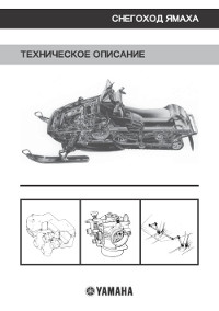
Описание конструкции снегохода Yamaha.
- Год издания: —
- Страниц: 65
- Формат: PDF
- Размер: 6,9 Mb
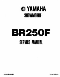
Руководство на английском языке по техническому обслуживанию и ремонту снегохода Yamaha BR250F.
- Год издания: 1981
- Страниц: 191
- Формат: PDF
- Размер: 8,7 Mb

Руководство по эксплуатации и техническому обслуживанию снегоходов Yamaha BR250TG и Yamaha VK540EG.
- Год издания: 2001
- Страниц: 88
- Формат: PDF
- Размер: 8,7 Mb
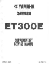
Дополнение к руководству по техническому обслуживанию и ремонту снегохода Yamaha ET300E.
- Год издания: 1980
- Страниц: 8
- Формат: PDF
- Размер: 790 Kb
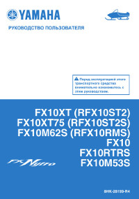
Сборник руководств по эксплуатации и техническому обслуживанию снегоходов Yamaha FX Nytro моделей FX10/RFX10 различных модификаций.
- Год издания: 2007-2012
- Страниц: 94/118/122
- Формат: PDF
- Размер: 32,0 Mb
Сборник руководств на английском языке по эксплуатации и техническому обслуживанию снегоходов Yamaha FX Nytro модели FX10 различных модификаций.
- Год издания: 2007-2011
- Страниц: 92/104
- Формат: PDF
- Размер: 18,5 Mb
Руководство на английском языке по техническому обслуживанию и ремонту снегохода Yamaha FX Nytro модели FX10 различных модификаций.
- Год издания: 2007
- Страниц: 410
- Формат: PDF
- Размер: 13,5 Mb

Руководство по эксплуатации и техническому обслуживанию снегоходов Yamaha MM700/VT700/VX700ER.
- Год издания: 2001
- Страниц: 100
- Формат: PDF
- Размер: 9,2 Mb

Сборник руководств на английском языке по эксплуатации и техническому обслуживанию снегоходов Yamaha MM600/MM700/SX600/VT600/VT700/VX600/VX700 различных модификаций.
- Год издания: 1998-2002
- Страниц: —
- Формат: PDF
- Размер: 32,0 Mb
Сборник руководств по эксплуатации и техническому обслуживанию снегоходов Yamaha PZ50/RPZ50 Venture различных модификаций.
- Год издания: 2006/2012
- Страниц: 110/120
- Формат: PDF
- Размер: 11,7 Mb

Сборник руководств на английском языке по эксплуатации и техническому обслуживанию снегоходов Yamaha PZ50 Phazer, Venture различных модификаций.
- Год издания: 2006-2009
- Страниц: 88/92/98/104
- Формат: PDF
- Размер: 21,6 Mb
Сборник руководств на английском языке по техническому обслуживанию и ремонту снегохода Yamaha PZ50 Phazer, Venture различных модификаций.
- Год издания: 2006-2007
- Страниц: 424/114
- Формат: PDF
- Размер: 21,2 Mb
Руководство на английском языке по техническому обслуживанию и ремонту снегоходов Yamaha PZ500C и Yamaha VT500XLC.
- Год издания: 1998
- Страниц: 209
- Формат: PDF
- Размер: 6,0 Mb

Руководство на английском языке по эксплуатации и техническому обслуживанию снегоходов Yamaha PZ 500D/PZ500MLD/VT500XLD.
- Год издания: 1999
- Страниц: 83
- Формат: PDF
- Размер: 2,4 Mb
Сборник руководств по эксплуатации и техническому обслуживанию снегоходов Yamaha RS10/RS90/RSG90/RST90 RS Vecror, RS Venture различных модификаций.
- Год издания: 2004/2011/2012
- Страниц: 100/108/162
- Формат: PDF
- Размер: 31,0 Mb
Сборник руководств на английском языке по эксплуатации и техническому обслуживанию снегоходов Yamaha RS90/RSG90/RST90 RS Vector, RS Venture различных модификаций.
- Год издания: 2004-2011
- Страниц: —
- Формат: PDF
- Размер: 63,5 Mb
Сборник руководств на английском языке по техническому обслуживанию и ремонту снегоходов Yamaha RS90/RSG90/RST90 RS Venture различных модификаций.
- Год издания: 2004/2006/2008
- Страниц: 414/202/299
- Формат: PDF
- Размер: 37,1 Mb

Сборник руководств по эксплуатации и техническому обслуживанию снегоходов Yamaha RX10/RXW10 Apex различных модификаций.
- Год издания: 2001-2012
- Страниц: —
- Формат: PDF
- Размер: 28,6 Mb

Сборник руководств на английском языке по эксплуатации и техническому обслуживанию снегоходов Yamaha RX90/RXW90 Apex различных модификаций.
- Год издания: 2002-2010
- Страниц: —
- Формат: PDF
- Размер: 48,2 Mb

Руководство на английском языке по эксплуатации и техническому обслуживанию снегоходов Yamaha SRX700G.
- Год издания: 2001
- Страниц: 84
- Формат: PDF
- Размер: 6,6 Mb

Сборник руководств по эксплуатации и техническому обслуживанию снегоходов Yamaha SXV60/SXV70/VT60/VT70 различных модификаций.
- Год издания: 2003
- Страниц: 113/127
- Формат: PDF
- Размер: 10,5 Mb

Сборник руководств на английском языке по эксплуатации и техническому обслуживанию снегоходов Yamaha SXV60/SXV70/VT60/VT70 различных модификаций.
- Год издания: 2001-2005
- Страниц: —
- Формат: PDF
- Размер: 48,3 Mb

Сборник руководств по эксплуатации и техническому обслуживанию снегоходов Yamaha VK10/VK10D RS Viking.
- Год издания: 2007/2012
- Страниц: 98/108
- Формат: PDF
- Размер: 15,6 Mb

Сборник руководств на английском языке по эксплуатации и техническому обслуживанию снегоходов Yamaha VK10L и Yamaha VK10X.
- Год издания: 2005/2007
- Страниц: 98/88
- Формат: PDF
- Размер: 7,9 Mb
Дополнение к руководству по техническому обслуживанию и ремонту снегоходов Yamaha VK10L/VK10W.
- Год издания: 2005-2006
- Страниц: 360/103
- Формат: PDF
- Размер: 12,2 Mb

Руководство по эксплуатации и техническому обслуживанию снегоходов Yamaha VK540E/VK540EC.
- Год издания: 2012
- Страниц: 82
- Формат: PDF
- Размер: 3,2 Mb

Сборник руководств на английском языке по эксплуатации и техническому обслуживанию снегоходов Yamaha VK540EG/VK540EK.
- Год издания: 2001/2004
- Страниц: 76
- Формат: PDF
- Размер: 4,8 Mb

Руководство на английском языке по техническому обслуживанию и ремонту снегохода Yamaha VK540EK.
- Год издания: 2000
- Страниц: 211
- Формат: PDF
- Размер: 4,9 Mb

Руководство по эксплуатации и техническому обслуживанию снегохода Yamaha VT500XL.
- Год издания: 2001
- Страниц: 84
- Формат: PDF
- Размер: 8,2 Mb
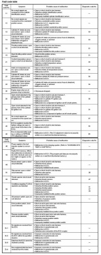
Коды неисправностей Yamaha.
- Год издания: —
- Страниц: 11
- Формат: JPG
- Размер: 1,7 Mb


A Yamaha VK Professional Snowmobile Repair Manual is an instruction handbook that contains all the information needed for repairing and performing maintenance on a snowmobile.
This type of repair manual—also referred to as a “factory service manual” or “workshop manual”—is a guidebook that gives you detailed instructions for performing maintenance on your 2006 thru 2010 VK Professional snowmobile, so you can keep your snowmobile running smoothly and efficiently. Additionally, it provides support for any technical issues you may encounter while owning and operating a VK Professional snowmobile. A table of contents at the beginning of the VK snowmobile repair manual allows you to quickly navigate the handbook to find the section you are looking for, and easy-to-follow directions guide you through each task step by step.
How is a repair manual helpful?
A repair manual can be very helpful to a VK Professional snowmobile owner. Not only is a repair manual rich with product-specific information, but it is also generally organized in such a way that any desired information is easy to find. This user-friendly format allows snowmobile owners with limited knowledge to successfully navigate the manual.
Here are a few reasons a repair manual is helpful:
-
- It is chalk-full of tips and content on properly caring for your VK Professional snowmobile, so you can extend the life of your snowmobile.
-
- It provides simple instructions that give you the opportunity to make most repairs yourself, saving you the cost of hiring a professional mechanic.
-
- It contains a robust offering of technical information and detailed instructions—including diagrams, photographs, and illustrations—that give you the tools you need to ensure you are repairing your Yamaha VK snowmobile correctly.
-
- It saves time. Attempting a repair on your own could lead to missing a step and wasting valuable time. Following the repair manual will ensure you do it right the first time.
- It is a direct source for reliable information, and likely the only immediate resource available to you when something goes wrong.
If you own a Yamaha VK Professional snowmobile, you should make sure you own a snowmobile repair manual as well. This all-important handbook will help you to be a successful snowmobile owner by making it easy for you to perform maintenance and repairs. A well-maintained snowmobile will require fewer repairs long-term and will increase the longevity of your snowmobile so you can enjoy snowmobiling for years to come. Any time maintenance or repairs are needed, you will be glad to have the most accurate and reliable source of information at your disposal.
References
Flare, Rick. “DOWNLOAD Yamaha VK Professional Repair Manual.” 911 Manual, 24 June 2019, https://www.911manual.com/yamaha-vk-professional-repair-manual/.
“Snowmobile.” Wikipedia, Wikimedia Foundation, 12 June 2019, en.wikipedia.org/wiki/Snowmobile.