Всем доброго дня!
Для удобства использования решил собрать в данной записи документацию, технические характеристики, мануалы, руководства, инструкции и прочий полезный материал для своей машины, найденные за несколько лет на просторах интернета. Предвижу, что данная подборка для местных олдовых корифеев покажется несколько скучной, тем не менее, не исключаю, что для кого-то она также может быть информативной и полезной. Информация актуальна для владельцев автомобилей Volvo C30/S40/V50/C70.
— Регламентированный перечень работ по ТО
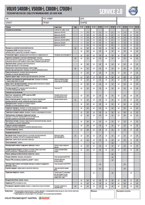
Регламентированный перечень работ по ТО для Volvo C30/S40/V50/C70
Ссылка на файл в формате PDF (ОД Обухов)
— Каталоги запчастей и аксессуаров Volvo
Carcats.ru
Elcats.ru
Emex.ru
accessories.volvocars.com — официальный каталог аксессуаров
Инструкция подбора запчастей и комплектующих Volvo по VIN-номеру — Часть 1, Часть 2
— Руководство/инструкция по эксплуатации
Ссылка на руководство для Volvo V50 MY2012
Ссылка на руководства для других моделей и/или модельных годов
Ссылка на различные инструкции для всех моделей Volvo (Eng, официальный сайт Volvo)
Ссылка на различные инструкции для Volvo S40/V50 (Eng, ресурс владельцев Volvo в UK)
— Quick Guide
Ссылка на файл в формате PDF
— Схемы соединений проводки (Электрика)
Полный размер
Схема по электрической проводке для Volvo C30/S40/V50/C70
Ссылка на файл в формате PDF
— Характеристики и годы производства двигателей для Volvo C30/S40/V50
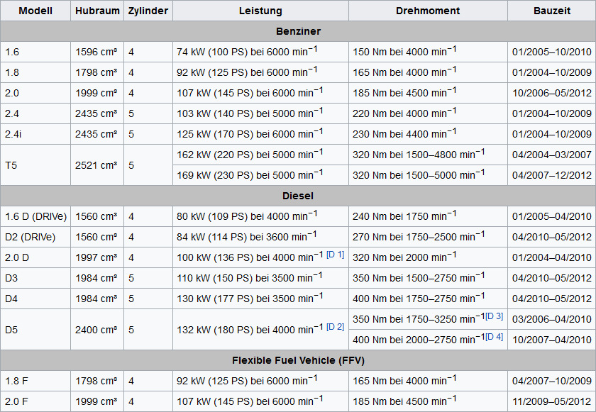
Характеристики и годы производства двигателей для Volvo C30/S40/V50
Ссылка на источник
— Технические характеристики бензиновых двигателей 2.4 (B5244S4/B5244S5) и 2.5 (B5254T3)
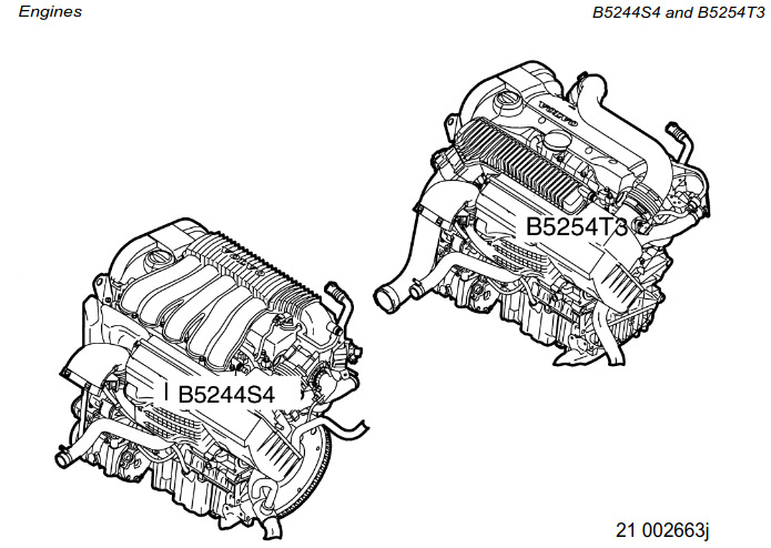
Manual Volvo C30/S40/V50 engines B5244S4 and B5254T3
Ссылка на файл в формате PDF (Eng)
— Технические характеристики бензинового двухлитрового двигателя B4204S3 (он же Mazda MZR LF 2.0, он же Ford Duratec HE 2.0)
Ссылка на изображение в полном размере (источник VIDA)
Ссылка на подборку полезной информации о двигателе Volvo B4204S3/Mazda MZR LF 2.0/Ford Duratec HE 2.0
— Моторное масло
Моторное масло — объём, допуск, эксплуатационные свойства, вязкость, артикулы канистр для бензиновых двигателей B4164S3, B4184S8, B4184S11, B4204S3, B4204S4, B5244S4, B5244S5, B5254T3, B5254T7 и дизельных двигателей D4162T, D4164T, D4204T, D4204T2, D5204T, D5204T5, D5244T8, D5244T9, D5244T13.
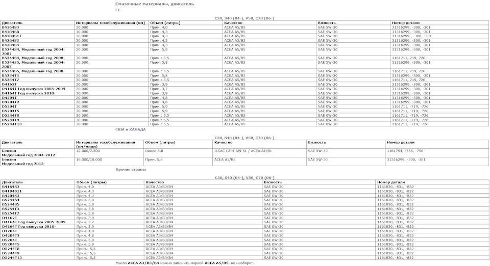
Полный размер
Моторное масло для двигателей Volvo C30/S40/V50
Ссылка на изображение в полном размере (источник VIDA)
— Объём масла между минимальной и максимальной отметками на щупе двигателей Volvo C30/S40/V50
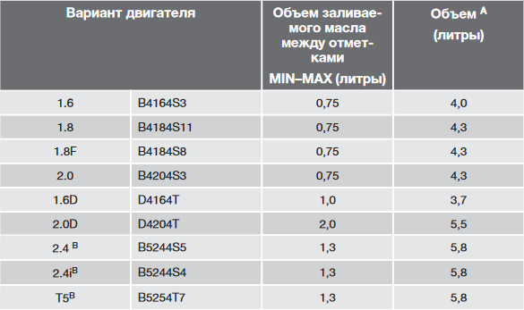
Объём масла между минимальной MIN и максимальной MAX отметкой на щупе моторов Volvo C30/S40/V50
— Автоматическая 5-ти ступенчатая коробка передач Aisin AW55-50/51SN
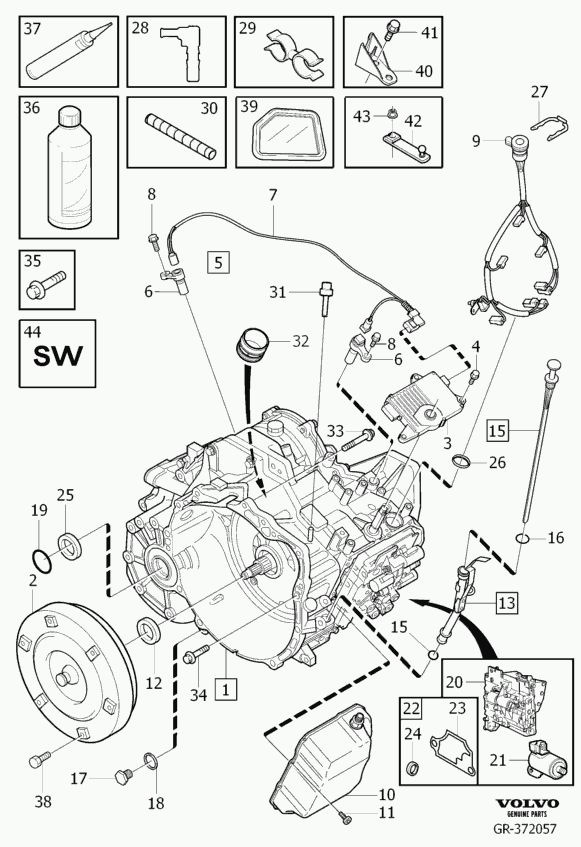
Запчасти на фото: 0835631, 303943
Ссылка на каталог запчастей в формате PDF (Eng)
Ссылка на мануал в формате PDF (Eng)
— Роботизированная 6-ти ступенчатая коробка передач Getrag 6DCT450 (MPS6, она же PowerShift)
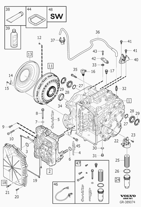
Серия публикаций о PowerShift от технического специалиста Сергея glimmer:
Эксплуатация PowerShift (6DCT450)
Функции коробки PowerShift (6DCT450)
Принцип работы Powershift 6DCT450
Замена масла в коробке PowerShift (6DCT450)
VIDA 2021: Инструкция по замене масла АКПП PowerShift (6DCT450) — NEW!
Замена сцепления 6DCT450 и Eco Boost 203(240)л.с)
Замена уплатнения сцепления 6DCT450 и Eco Boost 203(240)л.с
Модуль управления коробки передач (TCM). Часть 1
Модуль управления коробки передач (TCM). Часть 2
Модуль управления коробки передач (TCM). Замена датчика входного вала
Powershift 6DCT450 в деталях. Часть 1
Powershift 6DCT450 в деталях. Часть 2. Принципиальные схемы ТСМ
Powershift 6DCT450 в деталях. Часть 3. Демпфер.
Powershift 6DCT450 в деталях. Часть 4. Соленоиды ТСМ.
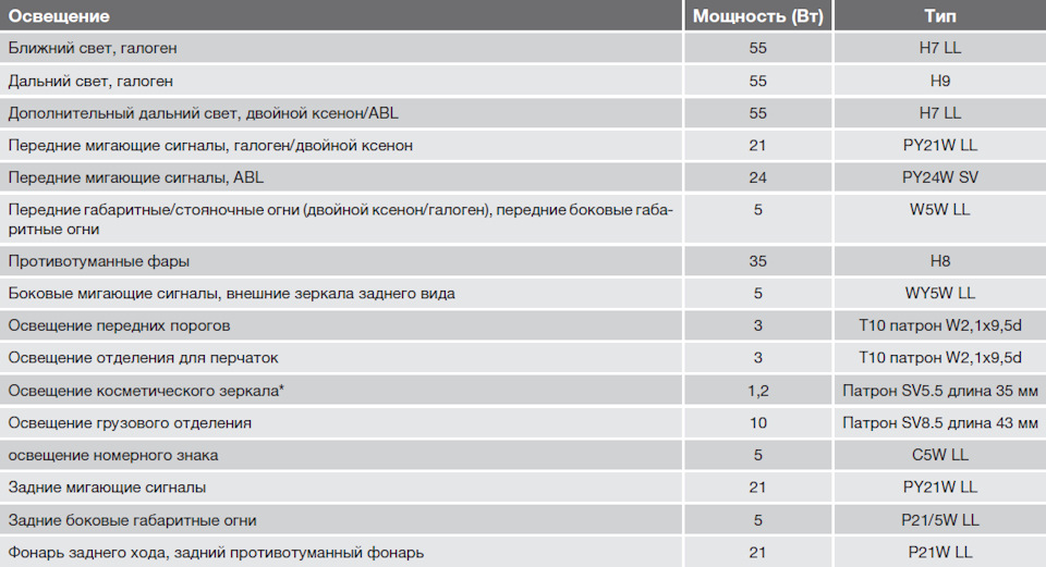
— Типы цоколей и мощность ламп
Полный размер
Типы цоколей и мощность ламп
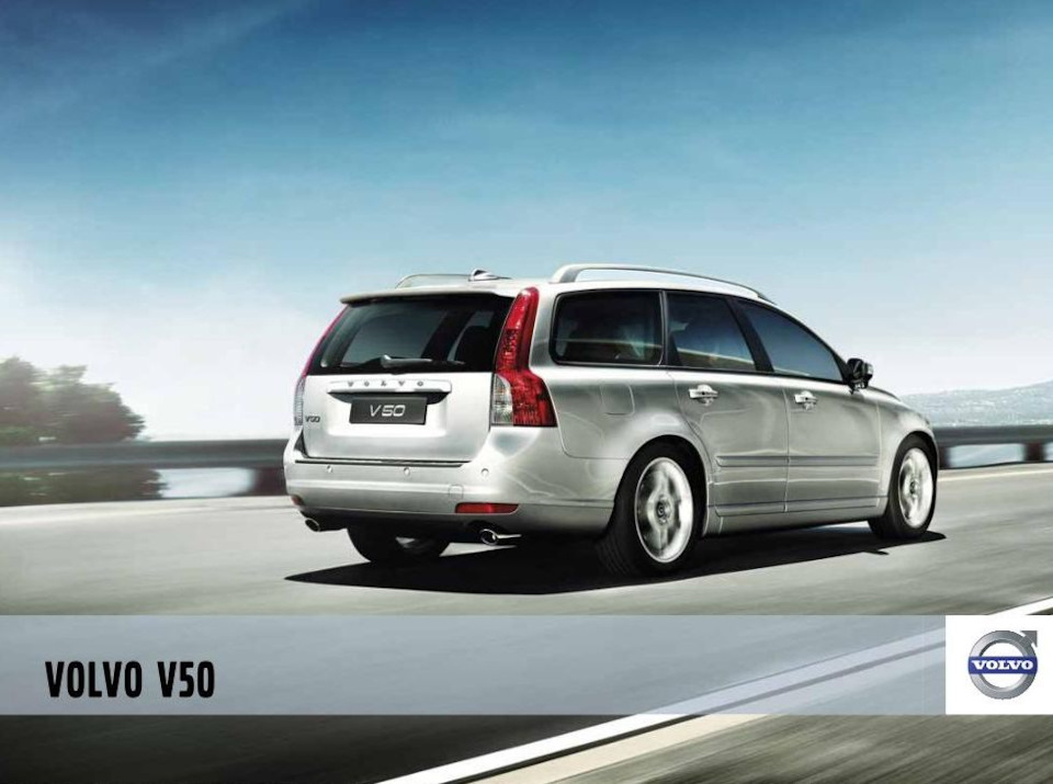
— Брошюра Volvo V50 (Volvo Cars Russia)
Полный размер
Брошюра Volvo V50 (Volvo Cars Russia)
Скачать в формате PDF — описание, фото, комплектации, экстерьер, интерьер, аксессуары
— Официальные пресс-релизы и фото Volvo V50 (Volvo Cars)
Ссылка на официальные пресс-релизы, фото и видео
— Каталог оригинальных литых дисков Volvo (артикулы и размерность)

Каталог оригинальных литых дисков Volvo
Ссылка на каталог — названия дисков, размерность и артикулы
— Комплектации Volvo V50
Ссылка
— Проверка доступности обновлений Service 2.0 для всех автомобилей Volvo по VIN-коду

Обновления Volvo Service 2.0
Ссылка
— Расшифровка информации о комплектации для всех автомобилей Volvo по VIN-коду
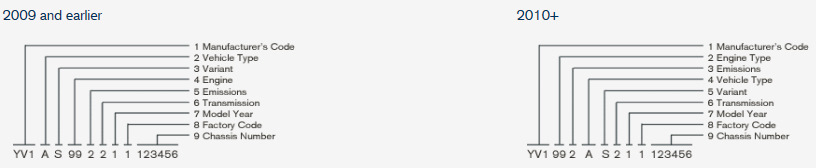
Ссылка на форму отправки запроса на расшифровку информации по VIN-коду в ОД Volvo Car M1
— Volvo VIDA
VIDA Online (для пользователей clubvolvo.ru)
VIDA 2014D + DiCE (Установка, настройка и использование)
— Кузов
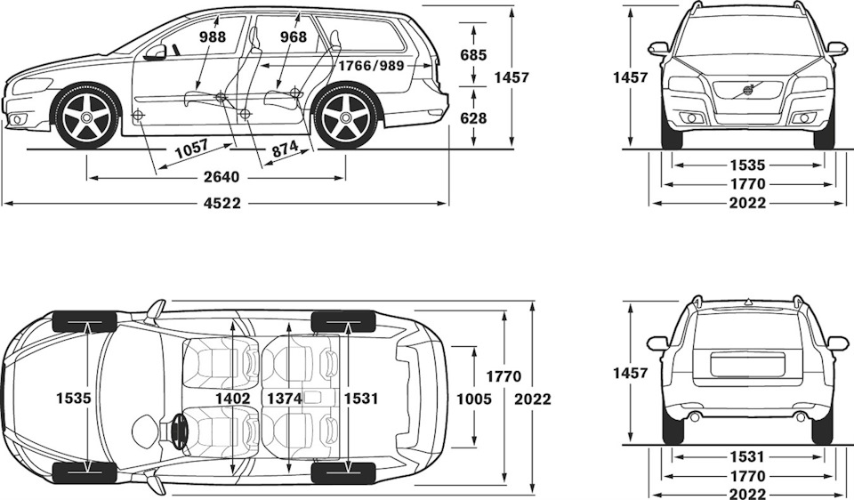
Полный размер
Размеры кузова Volvo V50

- Manuals
- Brands
- Volvo Manuals
- Automobile
- S40 — ANNEXE 244
- Manual
2005
-
Contents
-
Table of Contents
-
Bookmarks
Related Manuals for Volvo S40
Summary of Contents for Volvo S40
-
Page 1
VOLVO WEB EDITION 2005… -
Page 2
Dear Volvo owner We hope you will enjoy many years of driving pleasure in your Volvo. The car has been designed for the safety and comfort of you and your passengers. Volvo is one of the safest cars in the world. Your Volvo has also been designed to satisfy all current safety and environmental requirements. -
Page 3
In addi- tion to standard equipment, this manual also describes options (factory fitted equipment) and certain accessories (extra equipment). NOTE! Volvo cars are adapted for the varying requirements of different markets, as well as… -
Page 4: Volvo Cars And The Environment
, a concept which means that you benefit example in heavy city traffic, tailbacks and activities of Volvo Cars. Volvo cars comply in two ways — from a clean cabin and a highly tunnels — while the carbon filter traps nitrogen…
-
Page 5
In terms of fuel economy, significantly higher fuel ies and oils, in an envi- Volvo cars are highly competitive in their consumption, they ronmentally safe man- respective segments. should be removed ner. -
Page 6: Table Of Contents
Contents Instrument overview Safety Instruments and controls Climate control Interior Locks and alarm Starting and driving Wheels and tyres Car care Maintenance and service Infotainment system Technical data…
-
Page 8: Instrument Overview
Instrument overview Overview, left-hand drive car Overview, right-hand drive car Driver’s door control panel…
-
Page 9: Overview, Left-Hand Drive Car
Instrument overview Overview, left-hand drive car Left-hand drive…
-
Page 10
Instrument overview Steering wheel adjustment 25. Controls for climate control, infotainment system and personal Bonnet release preferences Control panel 26. Climate control Direction indicators, main beam, trip 27. Gear lever computer 28. Hazard warning flashers Lighting, fuel filler flap opener 29. -
Page 11: Overview, Right-Hand Drive Car
Instrument overview Overview, right-hand drive car Right-hand drive…
-
Page 12
Instrument overview Switch for retrofitted accessory 25. Cruise control STC or DSTC stability system 26. Combined instrument panel Electrical socket, cigarette lighter 27. Horn, airbag Parking brake 28. Keypad for infotainment system Control panel 29. Hazard warning flashers Glovebox 30. Door handle, central locking Door handle 31. -
Page 13: Driver’s Door Control Panel
Instrument overview Driver’s door control panel Blocking switch for rear power windows (standard) Electric child locks (option) Power windows Door mirror, left-hand side Door mirrors, setting Door mirror, right-hand side…
-
Page 14: Safety
Safety Seatbelts Airbags (SRS) Activating/deactivating the airbag (SRS) Side airbags (SIPS) Inflatable Curtain (IC) WHIPS When are the safety systems activated? Crash mode Inspecting the airbags and inflatable curtains Child safety…
-
Page 15: Safety
– Pull the belt out slowly and secure it by pulling the diagonal shoulder belt as Never modify or repair the seatbelts pressing the buckle into the lock. A loud illustrated. yourself. Contact an authorised Volvo «click» indicates that the belt has locked. workshop.
-
Page 16: Seatbelts
Safety reminder is heard that changes frequency with the speed of the car. Rear seat The seatbelt reminder has two sub-functions: • Notifies of the number of seatbelts being used via a message on the information display. This function is automatically activated as soon as a rear door is opened and closed, even if no one is actually sitting in the rear seat.
-
Page 17: Seatbelt Tensioner
Safety Seatbelts Seatbelt tensioner All the seatbelts (except the centre rear belt) are equipped with belt tensioners. A mechanism in the belt tensioner tightens the belt around the body in the event of a suffi- ciently violent collision. This provides more effective restraint for passengers.
-
Page 18
Safety Airbags (SRS) WARNING! To minimise the risk of injury if the airbag deploys, passengers must sit as upright as possible with their feet on the floor and backs against the backrest. Seatbelts must be secured. WARNING! Never place a child in a child seat or on a booster cushion in the front seat if the airbag (SRS) is activated. -
Page 19: Airbags (Srs)
AIRBAG system is not functioning fully. The symbol can indicate a fault in the seatbelt buckle, SIPS, SRS or IC system. Contact an authorised Volvo workshop immediately. As well as the warning symbol, a message appears on the Location of the passenger airbag in left-hand information display.
-
Page 20: Srs System
Work on the SRS system can cause malfunction and result in serious personal injury. Repairs must only be performed by an authorised Volvo workshop. Airbags (SRS) NOTE! The airbags have a function whereby their capacities are adapted to the collision force to which the vehicle is subjected.
-
Page 21: Activating/Deactivating The Airbag (Srs)
Check that the seat can be deactivated. This is necessary if activated. switch is in the required position. Volvo a child seat is to be placed there. recommends that that the ignition key is used Indicator to change position.
-
Page 22
This indicates that there has been a severe malfunction. Contact an authorised Volvo workshop as soon as possible. Switch for SRS in ON position. Switch for SRS in OFF position. -
Page 23: Side Airbags (Sips)
WARNING! A large proportion of the collision force is A child seat or booster cushion can be Use only Volvo genuine car seat covers, or transferred by the SIPS to the floor, roof, placed on the front passenger seat provided seat covers approved by Volvo.
-
Page 24: Sips Bag System
Safety Right-hand drive Left-hand drive SIPS bag system The SIPS bag system consists of a gas generator, side airbag and sensors. A suffi- ciently violent collision trips the sensors and ignites the gas generator, inflating the side airbag. The airbag inflates between the occupant and the door panel and thereby cushions the initial impact while deflating.
-
Page 25: Inflatable Curtain (Ic)
When deployed, the inflatable curtain This could compromise the intended inflates. The inflatable curtain helps to protection. Only use Volvo genuine parts prevent the driver and passengers from that are approved for placement in these striking their heads on the inside of the car areas.
-
Page 26
Never modify or repair the seat or WHIPS system yourself. Contact an authorised WARNING! Volvo workshop. The WHIPS system is a supplement to the seatbelts. Always wear your seatbelt. Correct seating position For the best possible protection, the driver… -
Page 27: Whips
Do not squeeze rigid objects between the If a rear seat backrest is folded down, the rear seat cushion and the front seat undamaged. Contact an authorised Volvo corresponding front seat must be moved backrest. Make sure you do not to…
-
Page 28: When Are The Safety Systems Activated
The deployed airbags. WARNING! smoke and dust created when the airbags • Let an authorised Volvo workshop replace The AIRBAG control unit is located in the are deployed can cause skin and eye components in the car’s safety system.
-
Page 29: Crash Mode
Always allow an authorised WARNING! Volvo workshop to check and restore the If the car is in CRASH MODE it must not car to normal status after CRASH MODE be towed. It must be transported to an has been displayed.
-
Page 30: Inspecting The Airbags And Inflatable Curtains
The decal on the door pillar(s) shows the Driver airbag dates (year, month) when you should contact Front passenger airbag an authorised Volvo workshop to inspect and, Side airbag on the driver’s side if necessary, replace the airbags, belt Side airbag on the passenger side tensioners and inflatable curtains.
-
Page 31: Child Safety
Volvo’s own child safety equipment is designed for your car. Use Volvo genuine equipment to best ensure that the mounting points and attachments are correctly For information on activated/deacti- For information on activated/deacti- positioned and are sufficiently strong.
-
Page 32
Safety Decals on the end of the dashboard Decal located on the car’s sun visor WARNING! Never place a child in a child seat or on a booster cushion in the front seat if the airbag (SRS) is activated . Failure to follow this advice can endanger the life of the child. -
Page 33
Safety Child safety Placement of children in the car Weight/age Outer rear seat Centre rear seat Front seat <10 kg Rear-facing child seat, secured with Rear-facing child seat, secured with Rear-facing child seat, secured with seatbelt and straps. Use a seatbelt, support legs and straps. -
Page 34: Integrated Booster Cushion
(option) (option) The outer rear seats have ISOFIX attachment Volvo’s integrated booster cushion for the points. Contact a Volvo dealer for further outer rear seats is specially designed to information on child safety equipment. provide optimum safety for children.
-
Page 35
Safety Child safety Check that: • the seatbelt is in contact with the child’s body and is not slack or twisted, and that the belt is positioned correctly across the shoulder. • the hip strap is low across the hips for optimum protection. -
Page 36: Fitting A Child Seat
It is important that the integrated booster cushion is properly secured. Therefore, leave replacement and any repair of the cushion to an authorised Volvo workshop. Do not modify or adapt the booster cushion in any way. Fitting a child seat Volvo has child safety products that are designed for and tested by Volvo.
-
Page 37
Safety… -
Page 38: Instruments And Controls
Instruments and controls Combined instrument panel Indicator and warning symbols Information display Electrical socket and switches on centre console Lighting panel Left-hand stalk switch Right-hand stalk switch Cruise control (option) Steering wheel keypad (option) Steering wheel adjustment, hazard warning flashers Parking brake, electrical socket Power windows Rearview and door mirrors…
-
Page 39: Instruments And Controls
Instruments and controls Combined instrument panel Speedometer Tachometer — Indicates engine speed 13. Knob for clock — Turn the knob to adjust in thousands of revolutions per minute the time Direction indicators, left (rpm) 14. Temperature gauge — Displays the Warning symbol Indicator and warning symbols temperature of the engine cooling…
-
Page 40: Indicator And Warning Symbols
All indicator and warning symbols light up – Rectify the fault as instructed or contact when the ignition key is turned to position II an authorised Volvo workshop. before starting. This is to check that the symbols/lights are working. When the engine When one of the car’s systems…
-
Page 41
Instruments and controls Indicator and warning symbols – Drive to an authorised Volvo workshop to have the ABS checked if the symbol remains lit. Rear fog lamp This symbol is lit when the rear fog lamp is on. STC or DSTC stability system A flashing symbol indicates that the stability system is operating. -
Page 42
SRS, SIPS, or IC any further. Transport the car to an system. Drive directly to an authorised Volvo authorised Volvo workshop to have the workshop to have the system checked. brake system checked. -
Page 43
Instruments and controls Indicator and warning symbols Reminder — doors not closed If one of the doors, the bonnet or the boot lid is not properly closed, the driver will be reminded of this. Low speed If the car is travelling at more than 7 km/h, the information symbol will light and one of the following texts will be shown on… -
Page 44: Information Display
Instruments and controls Information display Messages When a warning or indicator symbol come, a message appears on the information display. – Press the READ button (A). Switch between messages with the READ button. Fault messages are stored in the memory until the fault is rectified. NOTE! If a warning message appears while you are using the trip computer, the message must be read (press READ) before the…
-
Page 45: Electrical Socket And Switches On Centre Console
Instruments and controls Electrical socket and switches on centre console Pull out the lighter and light a cigarette on the heated coils. Stability system, STC or DSTC The stability control system comes on automatically when the car is started. To suppress the stability control system: –…
-
Page 46: Lighting Panel
Automatic control: can be deactivated. Contact an authorised To improve readability and save electricity, a Volvo workshop. Front and rear position/ twilight sensor automatically adjusts the parking lamps, number plate lighting and brightness of the instrument lighting.
-
Page 47: Rear Fog Lamp
Instruments and controls Lighting panel 6. Rear fog lamp Ignition key in position II: Press the button to switch on the rear fog lamp. The rear fog lamp lights along with the front fog lamps or main/dipped beam. The LED in the button and the symbol in the combined instrument panel light.
-
Page 48: Trip Computer
Instruments and controls Left-hand stalk switch Main beam flash (3) Pull the lever towards you (until you feel a slight resistance). The main beam remains lit until you release the lever. Switching between main and dipped beam (3) Pull the lever towards you past the «flash position»…
-
Page 49
Instruments and controls Left-hand stalk switch Range to empty fuel tank • SPEED IN MILES PER HOUR This calculation is based on the average fuel • CURRENT FUEL CONSUMPTION consumption over the last 30 km (19 miles) • AVERAGE FUEL CONSUMPTION and the remaining fuel volume. -
Page 50: Windscreen Wipers
Instruments and controls Right-hand stalk switch Single sweep The headlamps are washed the first time the Raise the stalk switch to make a windscreen is washed. Within the next ten single sweep. minutes, they are washed every fifth wash of the windscreen.
-
Page 51
Instruments and controls Right-hand stalk switch To activate the rain sensor: – press button (B). The rain sensor symbol is shown on the lower display. To turn the rain sensor off, either: – press button (B). – press the stalk switch downward to another wiper program. -
Page 52: Cruise Control (Option)
Instruments and controls Cruise control (option) Temporary disengagement – Press 0 to disengage the cruise control temporarily. CRUISE will be shown on the combined instrument panel. The speed set earlier is stored in the memory. The cruise control is also temporarily disen- gaged when: •…
-
Page 53: Steering Wheel Keypad (Option)
Instruments and controls Steering wheel keypad (option) The four buttons at the bottom of the steering wheel keypad control the radio and the telephone. The function of a button depends on which system is active. The steering wheel keypad can be used to scroll between preset stations, change CD/MD tracks and adjust the volume.
-
Page 54: Steering Wheel Adjustment
Instruments and controls Steering wheel adjustment, hazard warning flashers Steering wheel adjustment Hazard warning flashers The steering wheel can be adjusted for both Use the hazard warning flashers (all direction height and reach. indicators flash) when the car is stopped –…
-
Page 55: Parking Brake, Electrical Socket
Instruments and controls Parking brake, electrical socket Parking brake (handbrake) and coolers. The maximum current is 10 A. For the socket to supply current, the ignition The lever is located between the front seats. key must be in at least position I. The parking brake acts on the rear wheels.
-
Page 56: Power Windows
Instruments and controls Power windows Operation Automatic operation – Fully depress one of the controls (A) or The power windows are operated using the (B) or raise it fully, then release. The side controls in the door armrests. The ignition key window will then open or close automati- must be in position I or II for the power cally.
-
Page 57: Front Passenger Seat
Instruments and controls Power windows The switch LED is unlit The rear door windows can be operated both with the control on each rear door and with the controls on the driver’s door. Blocking rear power windows and electric Front passenger seat child safety locks Front passenger seat Blocking power windows in the rear…
-
Page 58
Instruments and controls Rear power windows The rear door windows can be operated with the control on each door or with the switch on the driver’s door. If the LED in the switch for blocking the rear power windows (located in the control panel in the driver’s door) is lit, the rear door windows can only be operated from the driver’s door. -
Page 59: Rearview And Door Mirrors
An authorised – Drive slowly in a circle at a speed of no Volvo workshop can adjust the sensitivity. more than 10 km/h until a compass direction appears on the display.
-
Page 60: Door Mirrors
Instruments and controls – The display will revert to showing the compass direction a few seconds after you stop scrolling. Magnetic zones Adjusting the zone Door mirrors The earth is divided into 15 magnetic zones. The controls for adjusting the two door The compass is set for the geographical area mirrors are at the front of the driver’s door to which the car was delivered.
-
Page 61
Instruments and controls Rearview and door mirrors Folding out the mirrors Important! – Press the L and R button at the same Do not use a scraper to remove ice from time. The mirrors automatically stop in the the mirrors as this can scratch the glass. fully extended position. -
Page 62
Instruments and controls Power sunroof (option) – Pull the control rearward to the end position (1) and release. Sliding position Automatic operation Pull the control past the point of resistance (2) to the rear end position (1) or past the point of resistance (3) to the forward end position (4) and release. -
Page 63
Instruments and controls Power sunroof (option) WARNING! Make sure that the hands of children and passengers are clear when closing the sunroof by remote control. Sunscreen The sunroof features a manual, sliding interior sunscreen. The sunscreen slides back automatically when the sunroof is opened. Grip the handle and slide the screen forwards to close the screen. -
Page 64: Personal Preferences
Instruments and controls Personal preferences and audio functions. For audio functions, see Recirculation timer page 183. When the timer is active, the air recirculates for 3-12 minutes, depending on the outside Control panel air temperature. A. Display – Select On/Off depending on whether you B.
-
Page 65: Approach Lighting
Instruments and controls Personal preferences • Drivers door first, then all others — one • Number of keys. The number of keys press of the remote control unlocks the registered for the car is shown. driver’s door. A second press then unlocks all the other doors.
-
Page 66: Climate Control
Climate control General information on climate control Manual climate control, A/C Electronic climate control, ECC (option) Air distribution Fuel-driven parking heater (option)
-
Page 67: Climate Control
Fault tracing windows to remove misting. Personal preferences An authorised Volvo workshop has the instru- Cold weather: Close the centre vents for You can set preferences for two climate ments and tools required for any fault tracing optimum comfort and best demisting.
-
Page 68
Climate control ECC (option) Condensation In warm weather, condensation from the air Actual temperature conditioning system may drip under the car. The temperature you select corresponds to This is normal. the physical experience with reference to factors such as air speed, humidity and solar radiation in and around the car. -
Page 69: Manual Climate Control, A/C
Climate control Manual climate control, A/C Control panel Functions 2. Recirculation Recirculation can be used to Recirculation 1. Fan shut out bad air, exhaust Defroster Increase or decrease the fan fumes, etc. from the Air distribution speed by turning the knob. passenger compartment.
-
Page 70
Climate control Timer in the button indicate which function has function is active if one LED is lit in the switch. The timer function minimises the risk of icing, been selected. The door mirror heating is deactivated misting and bad air if recirculation is selected. automatically after approximately 6 minutes. -
Page 71
Climate control Electronic climate control, ECC (option) Control panel AUTO Functions 2. Fan Increase or decrease fan 1. AUTO speed by turning the knob. Recirculation/Air quality system The AUTO function The fan speed is regulated Defroster automatically regulates automatically if AUTO is Air distribution climate control and selected and the previously… -
Page 72
Climate control 3. Recirculation A green LED (A) lights in the button when the 4. Defroster Recirculation can be used to air quality sensor is active. Defroster quickly removes shut out bad air, exhaust misting and ice from the Activating the air quality sensor: fumes, etc. -
Page 73
Climate control Electronic climate control, ECC (option) functions are still controlled automa tically. 10. Temperature selector When Defroster (4) is selected, the air condi- The temperatures on the tioning system is set for maximum dehumidifi- driver and passenger sides cation. can be set independently. -
Page 74: Air Distribution
Climate control Air distribution Air distribution Air distribution Use: Air distribution Use: Air to windows. Some To remove ice and Air to the floor and To ensure air flows to the misting quickly. windows. Some air comfortable condi- dashboard air vents. flows to the dashboard tions and good The air is not recircu-…
-
Page 75: Fuel-Driven Parking Heater (Option)
Climate control Fuel-driven parking heater (option) maximum running time of the parking heater is 60 minutes. WARNING! The car must be outdoors when the petrol or diesel heater is used. WARNING! Switch off the fuel-driven heater before refuelling. Spilled fuel could be ignited by the exhaust gases.
-
Page 76: Parking On A Hill
Climate control Activating the heater Battery and fuel – Scroll with the thumbwheel to the desired minute. – Enter the time when the car is to be used. If the battery has insufficient charge or the – Touch RESET to confirm the setting. Press RESET (C) to enter the hours and fuel level is too low, the parking heater will be minutes.
-
Page 77: Fuel-Driven Heater
Climate control Fuel-driven heater (option) Messages on the display When TIMER 1, TIMER 2 and DIRECT START are activated, the information symbol on the combined instrument panel lights and an explanatory text appears on the infor- mation display. The display also indicates which timer is active when the driver removes the key from the ignition to leave the car.
-
Page 78: Interior
Interior Front seats Interior lighting Storage spaces in the passenger compartment Rear seat Cargo area…
-
Page 79: Interior
Interior Front seats Backrest rake: turn the wheel. Control panel for power seat (option). Controls (2) and (3) are not present on all seat models. WARNING! Adjust the position of the driver’s seat before setting off, never while driving. Check that the seat is locked in position. Seating position Lowering the front seat backrest…
-
Page 80
Interior the door is opened within two minutes, the about 20 seconds before adjusting the seat driver’s seat returns to the stored position. again. Seat with memory function (option) Emergency stop Seat adjustment, memory 1 If the seat accidentally begins to move, press one of the buttons to stop the seat. -
Page 81: Interior Lighting
Interior Interior lighting • On — left side depressed, passenger compartment lighting is on. Automatic lighting The interior lighting switches on and off automatically when switch (2) is in the neutral position. See illustration. The lighting comes on and remains on for 30 seconds if: •…
-
Page 82: Vanity Mirror
Interior Vanity mirror The light comes on automatically when the cover is lifted. Option on certain markets.
-
Page 83
Interior Storage spaces in the passenger compartment… -
Page 84: Storage Spaces
Floor mats (option) Always secure large and heavy objects Volvo supplies floor mats specially manufac- with a seatbelt or cargo retaining straps. tured for your car. These should be properly anchored with the clips on the floor so they do not slide and get jammed beside or under the driver’s pedals.
-
Page 85: Rear Seat
Interior Rear seat Important! The head restraints can be damaged if they are not removed for loading. The centre head restraint must also be removed for heavy loads. Tipping the rear seat backrest Centre rear head restraint The rear seat backrests can be tipped All head restraints can be adjusted vertically forwards together, or individually, to make it to suit the height of the passenger.
-
Page 86
Interior WARNING! Remember to take down the seatbelts once you have raised the backrest. Lowering the backrest – Pull the lock (2) catch up and forward to release the backrest. A red indicator on the lock catch shows that the backrest is no longer locked in place. -
Page 87: Cargo Area
Interior Cargo area Load retaining eyelets Electrical socket in the cargo Bag holder (option) area The load retaining eyelets are used to fasten The bag holder holds shopping bags in place straps or nets to anchor items in the cargo and prevents them tipping over and spilling Fold down the cover to access the electrical area.
-
Page 88: Locks And Alarm
Locks and alarm Remote control with key blade Keyless drive (option) Locking and unlocking Child safety locks Alarm (option)
-
Page 89: Remote Control
— this contains the the other remote control to an authorised chip. The car cannot be started if the chip Volvo workshop. The code of the missing Locking — Locks the doors and the boot is damaged.
-
Page 90
Locks and alarm Removing the key blade Active locks, remote control symbol and REMOTE BATTERY LOW VOLTAGE appear on the display. Active locks, key blade To take the key blade out of the remote control: Service locking – Slide the spring-loaded catch (1) to the Locking the glovebox: Turn the key blade side while pulling the key blade (2) out. -
Page 91: Remote Control With Key Blade
Locks and alarm Remote control with key blade – Prise out (2) and change the battery. Avoid touching the battery and its terminals with your fingers. – Refit the cover and screw it shut. – Press the key blade back into place. Dispose of the old battery in an environmen- tally-friendly way.
-
Page 92
Locks and alarm Keyless drive (option) Keyless lock and ignition Remote control max. 1.5 m from the car The warning message and reminder signal To be able to open a door or the boot lid, the disappear when the remote control is system remote control must be within a maximum of brought back to the car after one of the… -
Page 93
Locks and alarm Keyless drive (option) Interference to remote control function All doors and the boot lid must be closed Electromagnetic screening and fields can before the lock button is pushed in. interfere with the keyless drive system. To Otherwise they will not lock. avoid this: When the car is locked, the lock buttons on Do not place the remote control near mobile… -
Page 94: Locking And Unlocking
Locks and alarm Locking and unlocking Locking/unlocking the car from be locked manually with their respective lock buttons. Pull the door handle twice to unlock outside and open the door from the inside. You can lock and unlock all the car’s doors and the boot lid simultaneously using the remote control.
-
Page 95
Locks and alarm Locking and unlocking Temporary deactivation of the deadlocks and any detectors If someone is going to stay in the car but you still want to lock the doors from the outside, the deadlocks can be disabled. – Insert the key into the ignition switch, turn it to position II and then back to position I or 0. -
Page 96: Child Safety Locks
Locks and alarm Child safety locks Electric child safety locks and disabling the rear window buttons (option) Press the switch on the driver’s door. A message appears on the information display. When the electric child safety locks are activated, the rear window buttons are disabled.
-
Page 97: Arming The Alarm
— the alarm has been triggered. If there is a fault in the alarm system, a message appears on the information display. Contact an authorised Volvo workshop. If the alarm system does not work correctly, let an authorised Volvo workshop examine the car.
-
Page 98: Alarm Signals
Locks and alarm Automatic alarm activation Alarm signals This function prevents you accidentally When the alarm is triggered, the following leaving the car without the alarm on. happens: If none of the side doors or the boot lid are • A siren sounds for 30 seconds. The siren opened within two minutes of disarming the has its own battery which is used if the alarm (and the car has been unlocked with…
-
Page 99
Locks and alarm Alarm (option) The detectors are reactivated the next time Testing the bonnet the ignition is switched on. – Sit in the car and deactivate the movement detector. If the car has deadlocks, these are also re- – Arm the alarm. Remain in the car and lock engaged. -
Page 100: Starting And Driving
Starting and driving General Refuelling Starting the car Keyless drive Manual gearbox Automatic gearbox All-wheel drive Brake system Stability system Parking assistance (option) Towing and recovery Start assistance Driving with a trailer Towing equipment Detachable towbar Loading Adjusting headlamp pattern…
-
Page 101: Starting And Driving
Starting and driving General Economical driving heavy loads, there is a risk that the engine Do not overload the battery and cooling system will overheat. Driving economically means driving smoothly The electrical functions in the car load the while thinking ahead and adjusting your battery to varying degrees.
-
Page 102: Filling Up With Fuel
Too much fuel can overflow in warm weather. Do not add cleaning additives to the petrol, unless recommended by Volvo. Fuel of a lower quality than that specified on page 216 should not be used as engine power and fuel consumption can be Diesel negatively affected.
-
Page 103: Starting The Car
Starting the engine emptied. certain engine types. Volvo strives to Petrol engine: minimise exhaust emissions by having the When the filter has become approx. 80% full –…
-
Page 104
Starting and driving Ignition keys and electronic Ignition switch and steering When the steering lock is immobiliser lock activated The ignition key must not hang with other If the front wheels are positioned so that 0 – Locked position keys or metal objects on the same key ring. there is tension in the steering lock, a warning The steering lock is The electronic immobiliser could be activated… -
Page 105: Keyless Drive
Starting and driving Keyless drive Starting the car To start the car: Instead of an ignition key, the car has an • Depress the clutch or brake pedal. ignition dial. The dial is used in the same way • Press in and turn the dial to position III. as the key.
-
Page 106: Manual Gearbox
Starting and driving Manual gearbox Gear positions, five-speed Reverse gear inhibitor, five-speed Gear positions, six-speed Only engage reverse gear when the car is (petrol) Depress the clutch pedal fully with each gear stationary. To engage reverse gear, the gear change. Remove your foot from the clutch Depress the clutch pedal fully with each gear lever must first be put in position N.
-
Page 107
Starting and driving Manual gearbox Reverse gear inhibitor, six-speed Gear positions, six-speed Reverse gear inhibitor, six-speed (petrol) (diesel) (diesel) Only engage reverse gear when the car is Only engage reverse gear when the car is Depress the clutch pedal completely for each stationary. -
Page 108: Automatic Gearbox
Starting and driving Automatic gearbox Cold start Safety systems When starting in low temperatures, the gear Cars with an automatic gearbox have special changes can sometimes feel hard. This is due safety systems: to the gearbox oil’s viscosity at low tempera- Keylock tures.
-
Page 109
Starting and driving Automatic gearbox R – Reverse The car must be stationary when R is selected. N – Neutral N is the neutral position. No gear is engaged and the engine can be started. Apply the parking brake when the car is stationary with the gear selector is in position N. -
Page 110
Starting and driving released. If the gear selector is moved to W – Winter + (plus) the car changes up a gear. The W button by the gear The selected gear is indicated in the selector engages and disen- combined instrument panel (see page 38). gages the winter programme W. -
Page 111: All-Wheel Drive
Starting and driving All-wheel drive All-wheel drive – AWD All-wheel drive is always engaged. All-wheel drive means that all four road wheels are driven at the same time. Power is automatically distributed between front and rear wheels. An electronically controlled clutch system distributes the power to the pair of wheels that grips best.
-
Page 112: Brake System
Starting and driving Brake system Brake servo Dampness can affect braking using engine braking more efficiently and characteristics requires the foot brake for only brief periods. If the car is rolling or is being towed with the Brake components become wet when the car engine turned off, the brake pedal must be Bear in mind that driving with a trailer puts an is driven in heavy rain, through pools of water…
-
Page 113
If the level in the brake fluid reservoir is normal, drive carefully to the nearest authorised Volvo workshop to have the brake system checked. If the brake fluid is under the MIN level in the brake fluid reservoir, do not drive further before topping up the brake fluid. -
Page 114: Stability System
Starting and driving Stability system When the system is in action, it may seem like Spin Control (SC) the car does not respond normally to acceler- The Stability Control function prevents the ation. This is because the system detects the drive wheels from slipping during acceler- amount of friction on the road surface and ation.
-
Page 115
Starting and driving Stability system Symbols on the combined The information symbol comes on and stays lit instrument panel ANTI-SKID SERVICE REQUIRED The symbol lights and goes appears on the information display out again after about together with the symbol. The STC 2 seconds or DSTC system has been switched off The symbol is lit for a system… -
Page 116
REQUIRED is shown on the infor- Rear parking assistance is deactivated mation display in the centre of the combined automatically when towing a trailer if a Volvo Provided that the parking assistance instrument panel together with the symbol. genuine trailer cable is used. -
Page 117
Starting and driving Parking assistance (option) Parking assistance sensors. Cleaning the sensors The sensors must be cleaned regularly to ensure that they work properly. Clean them with water and car shampoo. The sensors can react if covered by ice and snow. -
Page 118: Towing And Recovery
Starting and driving Towing and recovery Never tow the car to bump WARNING! start it The steering lock stays in the position it Jump start the car with a donor battery if the was in when the power was cut off. The battery is flat and the engine does not start.
-
Page 119: Towing Eye
Starting and driving Towing and recovery Important! The towing eye is only designed for towing on roads, not for pulling the car unstuck or out of a ditch. Call a recovery service for assistance. Towing eye Use the towing eye if the car needs to be towed on the road.
-
Page 120: Start Assistance
Starting and driving Start assistance ensure that the cars do not touch one WARNING! another. The battery can generate oxyhydrogen – Connect the red jump lead between the gas, which is highly explosive. One spark, positive terminal on the donor battery which can be generated if you connect the (1+) and the one in your car (2+).
-
Page 121: Driving With A Trailer
• The engine is loaded more heavily than National vehicle regulations can further limit usual when driving with a trailer. If the towing bracket is mounted at the Volvo trailer weights and speeds. Towbars can be factory, the car is delivered with the •…
-
Page 122
Starting and driving Automatic gearbox, driving with engine torque. Consult your Volvo dealer for information regarding your car’s a trailer specifications. Parking on a hill: – Apply the parking brake (handbrake). – Move gear selector to the parking position P. -
Page 123: Towing Equipment
An adapter is required if the car’s towbar has 13 pin electrics and the trailer has 7 pin WARNING! electrics. Use an adapter cable approved by Volvo. Make sure the cable does not drag on If the car is fitted with a Volvo detachable the ground. towbar: Follow the assembly instructions for the towball section carefully.
-
Page 124: Specifications
Starting and driving Specifications Distance B Fixed towbar: 72 mm Distance A Detachable towbar: 72 mm Fixed towbar: 1055 mm Detachable towbar: 1055 mm Maximum ball load: 75 kg…
-
Page 125: Detachable Towbar
Starting and driving Detachable towbar Fitting the towball – Ensure that the mechanism is in the – Check that the indicator window (3) unlocked position by turning the key shows red. – Remove the guard plug. clockwise. If the window does not show red, press in (1) and turn the locking wheel anticlockwise (2) until you hear a click.
-
Page 126
Starting and driving – Insert the towball section until your hear a – Check that the indicator window shows – Turn the key anticlockwise to the locked click. green. position. Remove the key from the lock. -
Page 127
Starting and driving Detachable towbar NOTE! Check that the towball section is NOTE! The trailer’s safety cable must be secure by pulling it up, down and back. If the attached to the attachment on the towbar. towball section is not fitted correctly then it must be removed and refitted in accordance with the previous steps. -
Page 128: Removing The Towball
Starting and driving Removing the towball – Push in the locking wheel and turn it – Turn the locking wheel down fully, until it anticlockwise until you hear a click. comes to a stop. Hold it in this position – Insert the key and turn it clockwise to the while pulling the towball rearward and unlocked position.
-
Page 129
Starting and driving Detachable towbar – Insert the guard plug. -
Page 130: Load Carriers
Volvo. the passengers’ combined weight. The car’s • Secure all loads to the load retaining Carefully follow the mounting instructions load carrying capacity is reduced by the eyelets with straps or web lashings.
-
Page 131: Adjusting Headlamp Pattern
WARNING! On cars with Bi-Xenon headlamps, all work on the lights should be carried out at an authorised Volvo workshop. Bi-Xenon headlamps must be handled with extreme care due to the high-voltage unit.
-
Page 132: Wheels And Tyres
Wheels and tyres General Tyre pressure Changing wheels Warning triangle and spare wheel Removing wheels Emergency puncture repair…
-
Page 133
Wheels and tyres General Driving characteristics and tyres tyre is chosen, the car must not be driven Tyre age faster than the speed rating of the tyre (for Even if tyres have a theoretical lifespan of up The tyres greatly affect the car’s driving example, class Q can be driven at a maximum to ten years, it is not recommended to drive characteristics. -
Page 134: Winter Tyres
When driving on winter space between the brake disks and the tyres, these must be fitted to all four wheels. wheels is too small. NOTE! Ask a Volvo dealer which rim and tyre types are most suitable. Important! Studded tyres…
-
Page 135: Temporary Spare
Rims and wheel nuts washer. Only use rims that are tested and approved NOTE! These nuts may also be used with by Volvo and which are Volvo genuine acces- steel rims. sories. There are two types of wheel nut, Locking wheel nuts depending on whether the rims are made of steel or aluminium.
-
Page 136: Tyre Pressure
Wheels and tyres Tyre pressure Checking the tyre pressure Check the tyre pressure regularly. The correct tyre pressure is shown in the tyre pressure table. The stated tyre pressures refer to cold tyres. (Cold tyres mean the tyres are the same temperature as the ambient temperature.) Driving with the wrong tyre pressure adversely affects the car’s driving characte-…
-
Page 137: Changing Wheels
(to decrease the risk of skidding). Wheels should be stored lying down or hanging up, and not standing up. Contact an authorised Volvo workshop if you are uncertain about tread depth. The arrow shows the tyre’s direction of rotation.
-
Page 138: Warning Triangle And Spare Wheel
Wheels and tyres Warning triangle and spare wheel Warning triangle The warning triangle is fitted on the inside of the boot lid attached with two clips. Follow the regulations for the use of a warning triangle. Place the warning triangle in a suitable place with regard to the traffic.
-
Page 139
Wheels and tyres Warning triangle and spare wheel Spare wheel and jack Putting the spare wheel and jack into the cargo area: The car’s original jack – Wind the jack to halfway (1). The marking The original jack should only be used for on the plate (2) should line up with the changing wheels. -
Page 140: Removing Wheels
Wheels and tyres Removing wheels Set up the warning triangle if a wheel must be – Cars with steel rims have removable – On each side of the car are two jacking replaced at a busy location. Make sure that wheel covers.
-
Page 141
Wheels and tyres Removing wheels Fitting the wheel – Clean the contract surfaces on the wheel and hub. – Put on the wheel. Tighten the wheel nuts. – Lower the car so that the wheel cannot rotate. – Tighten the wheel nuts crosswise. It is important that the wheel nuts are tightened properly. -
Page 142: Emergency Puncture Repair
Wheels and tyres Emergency puncture repair General The canister with the sealing fluid should be replaced before the best-before date has Cars which do not have a spare wheel are expired or after the emergency repair kit has instead equipped with an emergency been used.
-
Page 143
Wheels and tyres Emergency puncture repair The emergency puncture repair kit has limited abilities to seal tyres which have punctures in the wall of the tyre. Do not seal tyres with the emergency puncture repair kit if they have larger slits, cracks, irregularities or similar damage. -
Page 144
Wheels and tyres Inflating tyres – Pump up the tyre to the pressure – Objects with a volume of up to 50 litres Set up the warning triangle if a tyre must be specified on the tyre pressure label. can be pumped up with the compressor. inflated in an area close to traffic. -
Page 145
Wheels and tyres Emergency puncture repair Sealing punctured tyres – Connect the lead (5) to one of the car’s increase temporarily up to a maximum of 12 V sockets. 4 bar while the sealing liquid is being Set up the warning triangle if emergency tyre pumped in. -
Page 146
Wheels and tyres the compressor. If the tyre pressure is WARNING! below 1.3 bar, the tyre has not been suffi- Never stand next to the tyre when the ciently well sealed. The journey should compressor is running. Be particularly not be continued under these circums- observant of the tyre walls. -
Page 147
Treat the removed canister as hazardous The canister can be replaced by an autho- coloured case (3). waste. rised Volvo workshop or according to the – Remove the speed label (4) and date instructions. Changing the canister and hose after label (1), and open the safety catch (5). -
Page 148
Wheels and tyres – Remove the speed label (4) and date label (1), and open the safety catch (5). Loosen the case (3) and take it off. – Push down the button (8) while turning the canister (6) and the holder (9) clockwise. -
Page 149
Wheels and tyres… -
Page 150: Car Care
Car care Cleaning Touching up paintwork Rustproofing…
-
Page 151: Car Care
• Dry the car using a clean, soft chamois or leather upholstery. Treat the leather uphol- a water scraper. stery once or twice a year using Volvo’s Press the brake pedal lightly from time to time • Clean the wiper blades with a lukewarm leather care kit.
-
Page 152: Polishing And Waxing
Cleaning seatbelts Use water and a synthetic detergent. A special textile cleaning agent is available from you Volvo dealer. Make sure the seatbelt is dry before allowing it to retract. Polishing and waxing Polish and wax the car if the paintwork is dull or to give the paintwork extra protection.
-
Page 153: Touching Up Paintwork
Car care Touching up paintwork – Stir the primer well and apply using a fine brush or matchstick. Apply paint using a brush once the primer is dry. – For scratches, proceed as above, but mask around the damaged area to protect the undamaged paintwork.
-
Page 154: Inspection And Maintenance
• Regularly check and touch-up the rustproofing treatment as necessary. The car’s rustproofing does not normally require treatment for approximately 12 years. After that time, it should be treated at three- year intervals. If the car needs further treatment, please contact an authorised Volvo workshop.
-
Page 155
Car care… -
Page 156: Maintenance And Service
Maintenance and service Volvo service Self-maintenance Bonnet and engine compartment Diesel Oils and fluids Wiper blades Battery Replacing bulbs Fuses…
-
Page 157: Maintenance And Service
To keep your Volvo as safe and reliable as mation. system. Always contact an authorised Volvo possible, follow the Volvo service programme…
-
Page 158
• Washer fluid – The reservoir should be corrosive and toxic. Handle the battery in an well filled. Use washer antifreeze at environmentally-suitable way. Let your Volvo temperatures around freezing. dealer assist you. • Brake and clutch fluid – The level must be between the MIN and MAX marks. -
Page 159: Bonnet And Engine Compartment
Maintenance and service Bonnet and engine compartment Opening the bonnet Engine compartment 12. Relay and fuse box To open the bonnet: Washer fluid reservoir (4 cyl.) 13. Air filter Coolant expansion tank – Pull the handle on the far left under the Power steering fluid reservoir dashboard.
-
Page 160
Maintenance and service Diesel Fuel system Empty tank Draining condensation from the fuel filter Diesel engines are sensitive to contaminants. No special procedures are required if the tank Only use diesel from a well-known oil runs dry. The fuel filter separates condensation from company. -
Page 161: Oils And Fluids
Always use oil of the recommended grade suitable intervals for changing the oil and oil changes. Volvo recommends checking the oil and correct viscosity. filter. Shorter intervals are recommended if level every 2500 km. The most accurate Never use oil additives.
-
Page 162
Maintenance and service Checking the oil in a cold engine: the MIN mark on the dipstick. See – Wipe the dipstick clean before checking page 212 for capacities. the level. – Check the oil level using the dipstick. The Important! oil level must be between the MIN and Never fill above the MAX mark. -
Page 163
The fluid should be changed annually on cars Important! driven in conditions requiring hard, frequent Always use coolant with anti-corrosion agent as recommended by Volvo. New cars are filled with coolant that can withstand temperatures down to approximately -35 °C. -
Page 164
Maintenance and service braking, such as driving in mountains or tropical climates with high humidity. WARNING! If the brake fluid is under the MIN level in the brake fluid reservoir, do not drive further before topping up the brake fluid. The reason for the loss of brake fluid must be investigated. -
Page 165: Wiper Blades
Maintenance and service Wiper blades Changing the wiper blades – Lift up the wiper arm and position the wiper blade at 90 degrees to the wiper arm. – Pull the wiper blade off the shaft, straight out to the side. –…
-
Page 166
Maintenance and service Battery NOTE! Never fill above the maximum mark (A). The battery contains corrosive acid. Important! Always use distilled or deionised water (battery water). Avoid sparks and naked flames. • Tighten the caps properly. NOTE! The life of the battery is shortened if it becomes discharged repeatedly. -
Page 167: Changing The Battery
Maintenance and service Battery Changing the battery WARNING! Removing the battery: Batteries can generate oxyhydrogen gas, – Switch off the ignition and remove the key. which is highly explosive. A spark, which – Unscrew the cover over the battery. can be generated if you connect the jump –…
-
Page 168: Replacing Bulbs
WARNING! switch. On cars with Bi-Xenon headlamps, all work on the lights should be carried out at an authorised Volvo workshop. Bi-Xenon headlamps must be handled with extreme care due to the high-voltage unit.
-
Page 169: Main Beam
Maintenance and service Replacing bulbs Dipped beam Fitting a new bulb: Main beam Removing the cover and bulb: – Fit the new bulb. It can only be fitted in – Remove the entire lamp housing. one position. – Left-hand headlamp: –…
-
Page 170: Direction Indicators
Maintenance and service Position/parking lamps Direction indicators Side marker lamps – Pull out the bulb holder with a pair of – Twist the bulb holder anticlockwise and – Twist the bulb holder anticlockwise and pliers. Do not pull out the bulb holder by remove it.
-
Page 171
Maintenance and service Replacing bulbs – Press the bulb holder back into place and refit the cover. Fog lamps Removing the bulb holder – Switch off all lights and turn the ignition All bulbs in the rear lamp cluster can be key to position 0. -
Page 172: Courtesy Lighting
– Insert the connector and turn clockwise. – Refit the lens. after a faulty lamp has been replaced then an – Refit the entire lamp housing and screw it authorised Volvo workshop needs to be into place. consulted to rectify the fault.
-
Page 173
Maintenance and service Replacing bulbs Fitting the mirror glass: – First, press the three lugs at top edge of mirror glass back into position. – Then press the three lower lugs back into position. Cargo area Vanity mirror lighting – Insert a screwdriver and gently turn so Removing the mirror glass: that the lamp housing comes loose. -
Page 174
• Fuses 7—18 are of the «JCASE» type and should be replaced by Contact an authorised Volvo workshop to have the system checked. an authorised Volvo workshop. • Fuses 1—6 are of the «Midi Fuse» type and may only be replaced by an authorised Volvo workshop. -
Page 175
Maintenance and service Fuses Radiator fan………………. 50 A 16. Supply to infotainment system ……….30 A Power steering…………….80 A 17. Windscreen wipers …………..30 A Supply to passenger compartment fuse box……60 A 18. Supply to passenger compartment fuse box ……40 A Supply to passenger compartment fuse box…… -
Page 176
Maintenance and service 29. Fog lamp, front…………….15 A 30. Engine control module (ECM) ………….3 A 31. Alternator voltage regulator …………10 A 32. Injectors (5 cyl), oxygen sensor (4 cyl) intercooler (diesel), air preheater valve (diesel) ….10 A 33. -
Page 177
Maintenance and service Fuses Relay/fuse box in the passenger compartment The fuse box has 50 fuse positions. The fuses are located under the glovebox. The box also provides space for several spare fuses. Changing fuses: – Remove the trim concealing the fuse box by pressing in the pin in the centre of the clips (1) about 1 cm and then withdrawing the clips. -
Page 178
Maintenance and service 37. Reserve ………………..- 51. Auxiliary heater relay coil (PTC), front lights parking assistance…………… 10 A 38. Reserve ………………..- 52. ABS system ………………5 A 39. Reserve ………………..- 53. Power steering …………….10 A 40. Reserve ………………..- 54. -
Page 179
Maintenance and service Fuses 65. Infotainment system ……………5 A 66. Infotainment control module (ICM), infotainment relay coil10 A 67. Reserve ………………..- 68. Cruise control ………………5 A 69. Climate control, rain sensor…………5 A 70. Reserve ………………..- 71. Reserve ………………..- 72. -
Page 180: Infotainment System
Infotainment system Audio and telephone Control panel Audio functions Radio functions CD/MD (option) CD changer (option) Menu settings and options — Audio Telephone (option) Telephone functions Menu settings and options — Telephone…
-
Page 181: Infotainment System
Infotainment system Audio and telephone Audio and telephone system The exact specifications for these levels may vary between markets. Certain levels are not (option) offered on all markets. The options list (sub- The infotainment system integrates the audio woofer, CD/MD player, CD changer, and telephone functions.
-
Page 182: Control Panel
Infotainment system Control panel Control panel on centre console 14. Display – Displays options, menus and information POWER – Audio On/Off 15. Slot for inserting/ejecting PHONE – Telephone On/Off/Standby 16. Eject – CD/MD VOLUME – Volume control 17. Station preset buttons/CD changer disc CD/MD –…
-
Page 183
Infotainment system Control panel – Press EXIT to cancel, decline an option, or go back one step in the menu structure. – Press ENTER to confirm, select or scroll from one submenu to the next submenu. If the battery voltage is low, a message appears on the display. -
Page 184: Audio Functions
Infotainment system Audio functions Volume control Choose between BASS, TREBLE, FADER, BALANCE, SUBWOOFER Turn the volume knob clockwise or antic- (option), CENTRE, and SURROUND. lockwise to raise or lower the volume. The – Use the TUNING knob to set the level. volume can also be controlled using the The display shows a max-min scale.
-
Page 185
Infotainment system Audio functions Dolby Surround Pro Logic II Dolby Surround Pro Logic II – Use the navigation button or TUNING and the Dolby icon are trade- knob to set the level. (certain models) marks of Dolby Laboratories – Use the navigation button to select the Dolby Surround Pro Logic II, with its centre Licensing Corporation. -
Page 186: Radio Functions
Infotainment system Radio functions slowly in the selected direction and – Autostoring appears on the display and a increases speed after a few seconds. number of strong stations (max. 10) from Release the button when the desired the selected frequency band are stored in frequency appears on the display.
-
Page 187
Infotainment system Radio functions Radio Data System — RDS returns to the previous sound source and volume setting. RDS is a system that links together specific network transmitters. It is used, for example, Activating News to tune the correct frequency of a station –… -
Page 188
Infotainment system TP from all stations Interruptions for news from the – Select the menu for the sound source. – Select and press ENTER. current station – Select and press ENTER. TP search is shown on the display when the function –… -
Page 189
Infotainment system Radio functions Alarm • Rock music – Press ENTER for one or more of the listed programme types. The PTY symbol on the • Easy listening Alarms are transmitted automatically. The display lights up when the first selection function cannot be deactivated. -
Page 190: Resetting Rds Functions
Infotainment system Automatic frequency updating The function has three levels: – Press MENU. Select the menu for the Local • — Only interrupts if the signal is sound source and press ENTER. strong. – Select Advanced radio settings and press Distant •…
-
Page 191
Infotainment system CD/MD (option) Scan Important! Scan plays the first ten seconds of each Use only standard 12 cm CDs, no mini track. CDs. Do not use CDs with adhesive disc – Press SCAN. labels. The heat from the CD player may –… -
Page 192
Infotainment system Ejecting a CD/MD Press the eject button to eject the disc. For traffic safety reasons, a CD remains ejected for only 12 seconds. The player will then feed the disc back into the player and switch to pause mode (N/A MD). Press CD/MD to reactivate the player. -
Page 193
Infotainment system CD changer (option) Fast forward/reverse If the quality of the CD does not comply with Press and hold the left or right arrow on the the requirements of standard EN60908 or if navigation button to search within a track or it has been recorded using poor equipment, the whole disc. -
Page 194
Infotainment system Disc text Some CDs have title information. The infor- mation is displayed as text on the display. Activating disc text – Press MENU. Select the menu for the sound source and press ENTER. Disc text – Select and press ENTER. If information is stored on the disc, this is shown on the display. -
Page 195
Infotainment system Menu settings and options — Audio FM1/FM2 menu 6.2. Surround CD/MD (certain models) CD menu 6.2.1. Dolby Pro Logic II News Off/ Random 6.2.2. 3 channel TP On/Off News (Off 6.2.3. TP (Off 6.3. Subwoofer On /Off (option) 3.1. -
Page 196
Infotainment system CD changer menu CD/MD menu Random Random 1.1. News (Off 1.2. Single disc TP (Off 1.3. All discs Disc text (Off News (Off Audio settings TP (Off 5.1. Surround AM/FM (certain models) Disc text (Off 5.1.1. Dolby Pro Logic II Audio settings 5.1.2. -
Page 197
Infotainment system Telephone (option) Telephone system components… -
Page 198: Emergency Calls
Infotainment system 1. Antenna • Switch off the system near blasting work. • Let only authorised personnel service the The antenna is mounted on the roof. telephone system. 2. Steering wheel keypad Emergency calls The majority of the telephone functions can Emergency calls to alarm centres can be be controlled using the keypad.
-
Page 199
Infotainment system Telephone functions Double SIM cards IMEI number Many network operators offer double SIM To block the telephone, you must provide cards — one for your car and one for another your network operator with the telephone’s telephone. A double SIM card allows you to IMEI number. -
Page 200
Infotainment system PHONE – On/Off/Standby. MENU – Opens the main menu. ENTER – Accept a call, select in the menu or activate the telephone from standby. Press ENTER once to display the last dialled number. EXIT – Terminate/reject a call, scroll back in the menu, cancel a selection or erase entered digits/characters. -
Page 201: Making And Receiving Calls
(Intelligent Driver Information System) The See menu 5.5.3. This function only applies to telephone system into standby. IDIS system allows incoming telephone calls the Volvo integrated telephone system. Reactivating and text (SMS) messages to be delayed so – The system can be reactivated by Ending a call that the driver can concentrate on driving.
-
Page 202: Call Waiting
Infotainment system Press ENTER and return the handset to – Search for the desired name or phone its cradle. If the handset is already number in the phone book. Press ENTER removed from its cradle at the start of a to select.
-
Page 203: Phone Book
Infotainment system Telephone functions Scroll with the navigation button and press Call volume Copying entries between the SIM card ENTER to make a selection. and Phone book Control the call volume during the call by Copying from the SIM card to the phone pressing the buttons with the large and small Secret mode/ Secret mode…
-
Page 204
Infotainment system Calling from the memory space 1- ? ! , . : » ‘ ( ) – Press MENU. a b c 2 ä å à æ ç d e f 3 è é – Scroll downward using the navigation button (or the left arrow button on the g h i 4 ì… -
Page 205: Telephone Menu
Infotainment system Menu settings and options — Telephone Telephone menu 3.4. Speed dial 5.2.5. Français FR 3.4.1. Active 5.2.6. Italiano Call log 3.4.2. Select number 5.2.7. Nederlands 1.1. Missed calls 3.5. Empty SIM 5.2.8. Português BR 1.2. Received calls 3.6. Empty telephone 5.2.9.
-
Page 206
Infotainment system Menu options, description 2. Messages 3.3. Copy all Copy telephone numbers and names from 2.1. Read 1. Call log the SIM card to the telephone memory. Received text messages. Select whether to 1.1. Missed calls erase, forward, change or save the entire 3.3.1. -
Page 207
Infotainment system Menu settings and options — Telephone 4.2. Call waiting 5.2.1. English UK 5.5.2. Ring tone. There are seven different Select whether or not you want to be alerted 5.2.2. English US ring tones. during a phone call that there is another 5.2.3. -
Page 208: Technical Data
Technical data Type designations Dimensions and weights Engine specifications Capacities Fuel Catalytic converter Electrical system…
-
Page 209: Technical Data
Technical data Type designations Whenever contacting your Volvo dealer and when ordering spare parts and accessories for your car, it makes things easier if you know your car’s type designation, vehicle identification number and engine number. Type designation, VIN, maximum…
-
Page 210: Dimensions And Weights
Technical data Dimensions and weights Dimensions Trailer with brakes Length: 447 cm Maximum trailer Maximum Width: 177 cm weight towball load: Wheelbase: 264 cm 1.6 1200 kg 75 kg Front track: 154-155 cm 1.6D manual 1300 kg Rear track: 153-154 cm 1.8 1300 kg others 1500 kg Weights…
-
Page 211: Engine Specifications
Technical data Engine specifications 2.4i Engine designation B4164S3 B4184S11 B5244S5 B5244S4 Output (kW/rps) 74/100 92/100 103/83 125/100 (hp/rpm) 100/6000 125/6000 140/5000 170/6000 Torque (Nm/rps) 150/67 165/67 220/67 230/73 (kpm/rpm) 15.3/4000 16.8/4000 22.4/4000 23.4/4400 No. of cylinders Bore (mm) Stroke (mm) 81,4 83.1 1.60…
-
Page 212
Technical data 1.6D 2.0D 2.0D Engine designation B5254T3 D4164T D4204T D4204T2 Output (kW/rps) 162/83 81/67 100/67 98/67 (hp/rpm) 220/5000 110/4000 136/4000 133/4000 Torque (Nm/rps) 320/25-80 240/ 320/33 320/33 (kpm/rpm) 32.6/1500-4800 24.5/ 32.6/2000 32.6/2000 No. of cylinders Bore (mm) Stroke (mm) 93.2 88.3 2.52… -
Page 213: Engine Oil
If the system is topped up with a different Petrol engines: For extreme conditions, oil, contact the nearest authorised Volvo choose a fully synthetic engine oil to provide workshop for servicing. extra protection.
-
Page 214
Important! The recommended transmission fluid must be used to prevent damage to the gearbox. Do not mix with any other transmission fluid. If the transmission is topped up with a different fluid, contact an authorised Volvo workshop for servicing. Fluid… -
Page 215
Use a washer antifreeze recommended by Volvo mixed with water at temperatures 5 cyl. Petrol 6.5 litres below freezing. Fuel tank See page 215 1. Weights can vary depending on the engine variant. Contact an authorised Volvo workshop for the exact information. -
Page 216
Technical data Fuel Consumption, emissions and volume Emissions of CO Consumption Tank volume Engine Gearbox litre/100 km (litres) (g/km) B4164S3 Manual 5 speed (IB5) B4184S11 Manual 5 speed (MTX75) B5244S5 Manual 5 speed (M56) Automatic gearbox (AW55-50/51) 2.4i B5244S4 Manual 5 speed (M56) Automatic gearbox (AW55-50/51) B5254T3 Manual 6 speed (M66) -
Page 217
Technical data Fuel Fuel consumption and Petrol emissions of carbon dioxide Most engines can be run with octane ratings of 91, 95 and 98 RON. Official fuel consumption figures are based on a standard driving cycle in accordance • 91 RON must not be used in 4 cylinder with EU Directive 80/1268 comb. -
Page 218: Catalytic Converter
Technical data Catalytic converter Lambda-sond oxygen sensor The Lambda-sond is part of a control system intended to reduce emissions and improve fuel economy. An oxygen sensor monitors the oxygen content of the exhaust gases leaving the engine. This value is fed into an electronic system that continuously controls the injectors.
-
Page 219: Electrical System
Technical data Electrical system General 12 volt system with a voltage-regulated alter- nator. Single pole system in which the chassis and engine block are used as conductors. Battery Voltage 12 V 12 V 12 V Cold start capacity (CCA) 520 A 600 A* 700 A** Reserve capacity (RC)
-
Page 220
Technical data Bulbs Lighting Output W Socket 1. Dipped beam 2. Bi-Xenon 3. Main beam 4. Brake lights, reversing lamps, rear fog lamp BA15s 5. Direction indicators, front/rear (yellow) BAU 15s 6. Rear position/parking lamps, rear side marker lamps BAY15d 7. -
Page 221
Technical data… -
Page 222
Bulb holder ………..170 A/C …………..68 Defroster …………69 ABS …………..111 Diesel particle filter ……..102 Car care …………149 Additional heater ……….76 Dimensions ……….. 209 Car upholstery ……….150 Air conditioning ……….66 Dipped beam ……….168 Carbon dioxide ……….216 Air distribution ……….73 Direction indicators …… -
Page 223
Fog lamps ……….45 Fuel consumption ……215 Ignition keys ……….103 Magnetic zones ……….59 Fuel consumption, current ……48 Ignition system ……….91 Main beam ………… 168 Fuel filler flap ……..45 Immobiliser ……….88 Maintenance ……….155 Fuel system ……….159 Indicator symbols ……..39 Messages …………43 Fuses …………. -
Page 224
Power steering fluid ……..163 Service programme ……..156 Trailer weight ……….209 Power windows ……….55 Side airbags ……….. 22 Trip computer ……….47 Puncture repair kit ……..141 Side marker lamps ……..169 Type designation ……… 208 SIPS bag system ……….. 23 Tyre pressure ………. -
Page 225
WHIPS ………….25 WHIPS and child seat/booster cushion …25 Windscreen washer ……..49 Windscreen wipers ……..49 Winter tyres ……….133 Wiper blades ……….164… -
Page 226
6968 7459 (English). AT 0446. Printed in Sweden, Elanders Infologistics Väst AB, Mölnlycke 2004…
This manual is also suitable for:
2005 s40
Руководство на английском языке по техническому обслуживанию и ремонту автомбилей Volvo S40 и Volvo V40 1996-2004 годов выпуска с бензиновыми двигателями.
- Автор: —
- Издательство: Haynes Publishing
- Год издания: —
- Страниц: 308
- Формат: PDF
- Размер: 57,6 Mb

Мультимедийное руководство на английском языке по техническому обслуживанию и ремонту автомбилей Volvo S40 и Volvo V40.
- Автор: —
- Издательство: Mitchell
- Год издания: —
- Страниц: —
- Формат: ISO
- Размер: 661,9 Mb
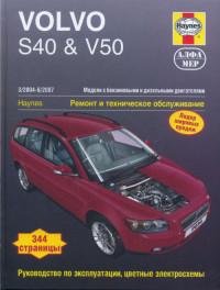
Руководство по эксплуатации, техническому обслуживанию и ремонту автомбилей Volvo S40 и Volvo V50 2004-2007 годов выпуска с бензиновыми и дизельными двигателями.
- Автор: —
- Издательство: Алфамер Паблишинг
- Год издания: —
- Страниц: 320
- Формат: PDF
- Размер: 122,7 Mb
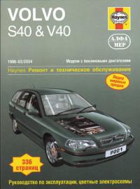
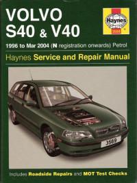
Руководство по эксплуатации, техническому обслуживанию и ремонту автомбилей Volvo S40 и Volvo V40 1996-2004 годов выпуска с бензиновыми двигателями.
- Автор: —
- Издательство: Алфамер Паблишинг
- Год издания: —
- Страниц: 295
- Формат: —
- Размер: —

Сборник руководств по эксплуатации и техническому обслуживанию автомбиля Volvo V40 Cross Country 2014-2015 годов выпуска.
- Автор: —
- Издательство: Volvo Car Corporation
- Год издания: 2013/2014
- Страниц: 540/472
- Формат: PDF
- Размер: 23,6 Mb
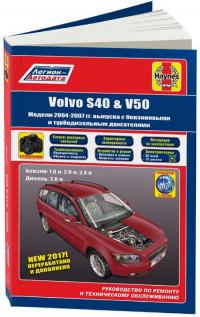
Руководство по эксплуатации, техническому обслуживанию и ремонту + каталог расходных запчастей автомбилей Volvo S40 и Volvo V50 2004-2007 годов выпуска с бензиновыми и дизельными двигателями.
- Автор: —
- Издательство: Легион-Автодата
- Год издания: —
- Страниц: 344
- Формат: —
- Размер: —
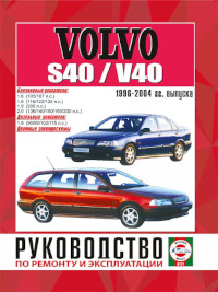
Руководство по эксплуатации и ремонту автомбилей Volvo S40 и Volvo V40 1996-2004 годов выпуска с бензиновыми и дизельными двигателями.
- Автор: —
- Издательство: Гуси-Лебеди
- Год издания: —
- Страниц: 280
- Формат: —
- Размер: —
Сборник руководств по эксплуатации и техническому обслуживанию автомбиля Volvo S40 с 2004 года выпуска.
- Автор: —
- Издательство: Volvo Car Corporation
- Год издания: 2003-2011
- Страниц: —
- Формат: PDF
- Размер: 66,1 Mb
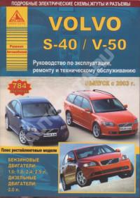
Руководство по эксплуатации, техническому обслуживанию и ремонту автомбилей Volvo S40 и Volvo V50 с 2003 года выпуска с бензиновыми и дизельными двигателями.
- Автор: —
- Издательство: Арго-Авто
- Год издания: —
- Страниц: 784
- Формат: —
- Размер: —


Данная инструкция на русском языке предназначена для автомобиля
Volvo S40 II (2007 — 2012), описывает принцип работы и основные моменты эксплуатации устройства.
Производитель настойчиво рекомендует перед включением автомобиля
внимательно изучить настоящую инструкцию.
Инструкция для автомобиля
представлена в формате PDF. Все современные браузеры уже поддерживают данный формат и сложностей с открытием файла возникнуть не должно.
Но если открыть инструкцию все же не удается, то необходимо установить на компьютер программу для чтения PDF файлов, например, Acrobat Reader. Если у вас возникли сложности с открытием инструкции на смартфоне под управлением Android, нужно установить, например, Adobe Acrobat Reader.
Комментарии (0)
Комментарии про другие Автомобили
Другие Автомобили Volvo

- Manuals
- Brands
- Volvo Manuals
- Automobile
- S40 — ANNEXE 244
- Owner’s manual
-
Contents
-
Table of Contents
-
Bookmarks
Quick Links
VOLVO S40
owner’s manual
WEB EDITION
Related Manuals for Volvo S40
Summary of Contents for Volvo S40
-
Page 1
VOLVO S40 owner’s manual WEB EDITION… -
Page 2
We hope that you will enjoy many years of driving pleasure in your Volvo. The car has been designed for the safety and comfort of you and your passengers. Volvo is one of the safest cars in the world. Your Volvo has also been designed to satisfy all current safety and environmental requirements. -
Page 3: Table Of Contents
02 Instruments and controls Introduction ……..6 Seatbelts ………. 12 Overview, left-hand drive cars ..34 Volvo Cars and the environment ..7 Airbag system ……..15 Overview, right-hand drive cars ..36 Airbags (SRS) ……..16 Driver’s door control panel ….38 Activating/deactivating the Combined instrument panel …..39…
-
Page 4
Contents 03 Climate control 04 Interior 05 Locks and alarm General information on climate Front seats ……..84 Remote control with key blade ..98 control ……….70 Interior lighting ……..86 Privacy locking (option) ….100 Manual climate control, AC ….72 Storage spaces in the passenger Active locks …….. -
Page 5
Contents 06 Starting and driving 07 Wheels and tyres 08 Car care General ……….. 116 General ……….. 156 Cleaning ………. 172 Refuelling ……..118 Tyre pressure ……..160 Touching up paintwork ….175 Starting the engine ……119 Warning triangle and spare Rustproofing …….. -
Page 6
Contents 09 Maintenance and service 10 Infotainment system 11 Specifications Volvo service ……..180 General ………..208 Type designation ……232 Self-maintenance ……181 Audio functions …….209 Specifications ……… 233 Bonnet and engine compartment .. 182 Radio functions …….212 Dimensions and weights ….234 Diesel ………. -
Page 7: Introduction
Owner’s Manual NOTE A good way of getting to know your new car Volvo cars are adapted for the varying is to read the Owner’s Manual, ideally before requirements of different markets, as well your first journey. This will give you the…
-
Page 8: Volvo Cars And The Environment
EPI (Environmental Product Information) is consumption. For more information read consideration for the environment. supplied for all Volvo models. Here you can under the heading Reducing environmental Your Volvo complies with strict international see how the environment is affected during impact on page 8.
-
Page 9
Textile standard Reducing environmental impact Your Volvo is manufactured following the The interior of a Volvo is designed to be You can easily help reduce environmental concept Clean inside and out – a concept pleasant and comfortable, even for people… -
Page 10
Introduction Volvo Cars and the environment • Drive in the highest gear possible. Low engine speeds result in lower fuel consumption. • Use engine braking to slow down. • Avoid idling. Take consideration of local regulations. Switch off the engine in longer stationary traffic. -
Page 11
Seatbelts ………………..12 Airbag system ………………15 Airbags (SRS) ………………. 16 Activating/deactivating the airbag (SRS) ………………… 18 Side airbags (SIPS bags) ……………..20 Inflatable Curtain (IC) …………….22 WHIPS ………………….23 When the systems deploy …………….25 Crash mode ………………..26 Child safety ………………..27… -
Page 12
SAFETY… -
Page 13: 01 Safety
• if it is pulled out too quickly. Never modify or repair the seatbelt yourself. • during braking and acceleration. Contact an authorised Volvo workshop. If • if the car leans heavily. the seatbelt has been subjected to a major…
-
Page 14
01 Safety Seatbelts Seatbelts and pregnancy the vehicle as they drive (which means that Seatbelt reminder they must be able to easily operate the foot pedals and steering wheel). They should strive to position the seat with as large a dis- tance as possible between their abdomen and the steering wheel. -
Page 15
01 Safety Seatbelts when the seatbelts are being used or Seatbelt tensioner when the rear doors are opened. The All the seatbelts are equipped with seatbelt message is automatically cleared after tensioners. A mechanism in the seatbelt ten- approx. 30 seconds or it can be acknow- sioner tightens the belt around the body in ledged manually by pressing the READ the event of a sufficiently violent collision. -
Page 16: Airbag System
The symbol indicates a fault in the seatbelt buckle, SIPS, SRS system or IC The airbag system is continually monitored system. Contact an authorised Volvo work- by the system control module. The warning shop urgently. symbol in the combined instrument panel illuminates when the ignition key is turned to position I, II or III.
-
Page 17: Airbags (Srs)
01 Safety Airbags (SRS) Airbag (SRS) on the driver’s side Passenger airbag (SRS) WARNING Never place a child in a child seat or on a booster cushion in the front seat if the air- bag (SRS) is activated. Never allow a child to stand or sit in front of the front passenger seat.
-
Page 18
01 Safety Airbags (SRS) SRS system SRS system, left-hand drive SRS system, right-hand drive Location of the passenger airbag in left-hand The system consists of airbags and sensors. drive and right-hand drive cars NOTE A sufficiently violent collision trips the sen- sors and the airbag(s) are inflated with hot The sensors react differently depending on WARNING… -
Page 19: Activating/Deactivating The Airbag (Srs)
Switch – PACOS below). Check that the ignition position II or III the warning symbol activate/deactivate, see page 19. switch is in the required position. Volvo rec- for the airbag is shown in the combined in- ommends that the key blade is used to strument panel for approx.
-
Page 20
This indicates that there has been a severe malfunction. Visit an authorised Volvo workshop urgently. Switch location 1. The airbag is activated. With the switch in this position, persons taller than 140 cm… -
Page 21: Side Airbags (Sips Bags)
Side airbag locations WARNING Use only Volvo genuine car seat covers, or A large proportion of the collision force is seat covers approved by Volvo. Other seat transferred by the SIPS (Side Impact Protec-…
-
Page 22
01 Safety Side airbags (SIPS bags) SIPS bags Driver’s side, left-hand drive cars Passenger side, left-hand drive cars Location of airbag decal in door opening on front passenger side in left-hand drive cars. The SIPS bag system consists of side air- bags and sensors. -
Page 23: Inflatable Curtain (Ic)
Only heads on the inside of the car during a WARNING use Volvo genuine parts that are approved collision. for placement in these areas. The inflatable curtain is a supplement to the seatbelts.
-
Page 24: Whips
Contact an authorised The WHIPS system is a supplement to the centre of the seat with as little space as pos- Volvo workshop. seatbelts. Always wear your seatbelt. sible between the head and the head restraint.
-
Page 25
Volvo workshop. Part of the WHIPS system’s protective ca- pacity may have been lost even if the seat appears to be undamaged. Contact an authorised Volvo workshop to have the system checked after even a minor rear-end collision. WARNING… -
Page 26: When The Systems Deploy
• Let an authorised Volvo workshop replace may deploy. Have the car transported to an injury after intensive exposure. In case of components in the car’s safety system.
-
Page 27: Crash Mode
This could result in personal sensors for one of the safety systems, or the injury or the car not functioning as normal. brake system. Always allow an authorised Volvo workshop to check and restore the car to NORMAL MODE after…
-
Page 28: Child Safety
Child seats and airbags are not compatible. WARNING Volvo’s own child safety equipment is Volvo has child safety products that are designed for your car. Use Volvo genuine Never place a child in a child seat or on a designed for and tested by Volvo.
-
Page 29
01 Safety Child safety Airbag decal WARNING Booster cushions/child seats with steel braces or some other design that could rest on the seatbelt buckle’s opening button must not be used, as they could cause the seatbelt buckle to open accidentally. Do not allow the upper section of the child seat to rest against the windscreen. -
Page 30
Outer rear seat Centre rear seat Front seat Group 0 Volvo Child seat – rear-facing child seat, Volvo Child seat – rear-facing child seat, Volvo Child seat – rear-facing child seat, max. 10 kg secured with the car’s seatbelt and secured with the car’s seatbelt, straps… -
Page 31
For information on activated/deactivated airbag (SRS), see page 18. – Pull that handle to raise the booster Volvo’s integrated booster cushion for the cushion (1). outer rear seats is specially designed to pro- – Grasp the cushion with both hands and vide optimum safety for children. -
Page 32
• Carefully adjust the position of the head restraint to suit the child. WARNING Repair or replacement should only be per- formed by an authorised Volvo workshop. Do not make any modifications or additions to the booster cushion. If an integrated booster cushion has been –… -
Page 33
Overview, left-hand drive cars …………..34 Overview, right-hand drive cars ……………36 Driver’s door control panel ……………38 Combined instrument panel …………..39 Indicator and warning symbols …………..40 Information display ……………….44 Electrical socket ………………45 Lighting panel ……………….46 Left-hand stalk switch …………….49 Right-hand stalk switch …………….51 Cruise control (option) …………….53 Steering wheel keypad (option) …………..54 Steering wheel adjustment, hazard warning flashers ……55… -
Page 34
INSTRUMENTS AND CONTROLS… -
Page 35: 02 Instruments And Controls
02 Instruments and controls Overview, left-hand drive cars…
-
Page 36
02 Instruments and controls Overview, left-hand drive cars 1. Steering wheel adjustment 26. Climate control 2. Bonnet release 27. Gear lever 3. Control panel 28. Hazard warning flashers 4. Direction indicators, main beam, trip computer 29. Door handle 5. Lighting, fuel filler flap opener 30. -
Page 37: Overview, Right-Hand Drive Cars
02 Instruments and controls Overview, right-hand drive cars…
-
Page 38
02 Instruments and controls Overview, right-hand drive cars 1. Electrical socket, cigarette lighter 26. Combined instrument panel 2. Blind Spot Information System, BLIS 27. Horn, airbag 3. Switch, optional equipment 28. Keypad for infotainment system 4. Parking brake 29. Hazard warning flashers 5. -
Page 39: Driver’s Door Control Panel
02 Instruments and controls Driver’s door control panel Driver’s door control panel 1. Blocking switch for rear power windows (standard) Electric child locks (option) 2. Power windows 3. Door mirror, left-hand side 4. Door mirrors, setting 5. Door mirror, right-hand side…
-
Page 40: Combined Instrument Panel
02 Instruments and controls Combined instrument panel 1. Speedometer. 6. Direction indicator, right. 11. Display – Display for automatic gear position, rain sensor, odometer, trip 2. Direction indicators, left. 7. Tachometer – Indicates engine speed meter and cruise control. in thousands of revolutions per 3.
-
Page 41: Indicator And Warning Symbols
02 Instruments and controls Indicator and warning symbols Functionality check, symbols Symbols in the centre of the – Read the information on the information display. Implement the action in accord- instrument panel All indicator and warning symbols illuminate ance with the message on the display. when the ignition key is turned to position II Clear the message using READ.
-
Page 42
8 litres – Restart the engine. of usable fuel left in a petrol- – Drive to an authorised Volvo workshop to engined car, or approximately have the ABS checked if the symbol 7 litres in a diesel-engined car. -
Page 43
SRS, SIPS, or IC the electrical system. Contact an system. Drive directly to an authorised Volvo workshop. authorised Volvo workshop to have the sys- tem checked. 7. Fault in brake system If this symbol illuminates, the 4. Low oil pressure brake fluid level may be too low. -
Page 44
High speed be driven, with great care, to an author- If the car is moving faster than ised Volvo workshop to have the brake approx. 7 km/h, the symbol illu- system checked. minates and one of the texts indi- •… -
Page 45: Information Display
Time to book regular service at an authorised Volvo workshop. TIME FOR REGULAR SERVICE Time for regular service at an authorised Volvo workshop. The timing is determined by the number of kilometres driven, number of months since the last service, engine running time and oil grade.
-
Page 46: 12 V Electrical Socket
02 Instruments and controls Electrical socket 12 V electrical socket Cigarette lighter (option) Electrical socket in the rear seat Activate the lighter by pushing in the button. The button pops out when the lighter is hot. Pull out the lighter and light a cigarette on the heated coils.
-
Page 47: Lighting Panel
If necessary, the auto- matic dipped beam can be deactivated by an The load in the car changes the vertical align- authorised Volvo workshop. ment of the headlamp beam, which could dazzle oncoming motorists. Avoid this by Automatic dipped beam, main beam adjusting the height of the beam.
-
Page 48
02 Instruments and controls Lighting panel The displays extinguish when the car is Active Bi-Xenon Lights (option) locked. Fog lamp NOTE Regulations for use of fog lamps vary from country to country. Front fog lamps (option) The front fog lamps can be switched on along with the headlamps or the position lamps/parking lamps. -
Page 49
02 Instruments and controls Lighting panel Brake light The brake light automatically comes on dur- ing braking. Emergency brake light and automatic hazard warning flashers, EBL Emergency Brake Lights (EBL) are activated in the event of heavy braking or if the ABS brakes are activated. -
Page 50: Left-Hand Stalk Switch
02 Instruments and controls Left-hand stalk switch Stalk switch positions Short flash sequence – Remove the key from the ignition switch. – Move the stalk switch up or down to – Move the stalk switch towards the steer- position (1) and release. ing wheel to the end position (4) and release.
-
Page 51
02 Instruments and controls Left-hand stalk switch Trip computer (option) Functions AVERAGE The trip computer displays the following The average fuel consumption is stored information: when the ignition is switched off and remains until the function is reset. Reset using the •… -
Page 52: Right-Hand Stalk Switch
02 Instruments and controls Right-hand stalk switch Windscreen wipers Single sweep Windscreen/headlamp washer Raise the stalk switch to make a Pull the stalk switch towards the steering single sweep. wheel to start the windscreen and headlamp washers. The wipers will make several extra sweeps once the stalk is released.
-
Page 53
02 Instruments and controls Right-hand stalk switch Rain sensor (option) Activating the rain sensor: – Press the button (B). A display symbol shows that the rain sensor is active. To turn the rain sensor off, either: – Press button (B) –… -
Page 54: Cruise Control (Option)
02 Instruments and controls Cruise control (option) Activating Increasing or decreasing speed Temporary disengagement – Press 0 to disengage the cruise control temporarily. CRUISE will be shown on the combined instrument panel. The speed set earlier is stored in the memory. The cruise control is also temporarily disen- gaged when: •…
-
Page 55: Steering Wheel Keypad (Option)
02 Instruments and controls Steering wheel keypad (option) Button functions The four buttons at the bottom of the steering wheel keypad control the radio and the phone. The function of a button depends on which system is active. The steering wheel keypad can be used to scroll between preset stations, change CD tracks and adjust the volume.
-
Page 56: Steering Wheel Adjustment, Hazard Warning Flashers
02 Instruments and controls Steering wheel adjustment, hazard warning flashers Steering wheel adjustment Hazard warning flashers Use the hazard warning flashers (all direction The steering wheel can be adjusted for both indicators flash) when the car is stopped height and reach. where it could be a traffic hazard or obstruc- –…
-
Page 57: Parking Brake
02 Instruments and controls Parking brake Parking brake (handbrake) – If the vehicle rolls, the parking brake lever must be pulled more firmly. When parking a vehicle always put the gear selector in 1st gear (for manual transmission) or P (for automatic transmission) Parking on a hill If the car is parked facing uphill;…
-
Page 58: Power Windows
02 Instruments and controls Power windows Operation Driver’s door dow is obstructed by an object, the move- ment will stop. The power windows are operated using the controls in the doors. The ignition key must WARNING be in position I or II for the power windows to operate.
-
Page 59
02 Instruments and controls Power windows Blocking power windows in the rear Rear power windows NOTE doors If the car has electric child safety locks on the rear doors, the light indicates that these are also activated. The doors then cannot be opened from the inside. -
Page 60: Rearview And Door Mirrors
02 Instruments and controls Rearview and door mirrors Interior rearview mirror Rearview mirror with compass (option Calibrating the compass on certain markets) The earth is divided into 15 magnetic zones. Bright light from behind could be reflected in The compass is set for the geographical area The upper right-hand corner of the rearview the rearview mirror and dazzle the driver.
-
Page 61
02 Instruments and controls Rearview and door mirrors – Press the button (1) repeatedly until the number for the required magnetic zone 1–15 ) is shown, refer to the map of mag- netic zones for the compass. – Wait until the display returns to showing the character –… -
Page 62
02 Instruments and controls Rearview and door mirrors Door mirrors Retractable power door mirrors – Release the buttons. The mirrors automat- ically stop in the fully extended position. (option) The mirrors can be retracted for parking and Resetting to neutral driving in narrow spaces. -
Page 63
02 Instruments and controls Rearview and door mirrors Water and dirt-repellent coating (option) The front windows and/or door mir- rors are treated with a coating which improves the view in poor weather conditions. For informa- tion on maintenance, see page 173. Rearview and door mirrors In certain weather conditions, the function of the dirt-repellent coating is improved if the… -
Page 64: Power Sunroof (Option)
02 Instruments and controls Power sunroof (option) Open positions From ventilation position to fully open sun- roof: – Pull the control rearward to the end position (1) and release. Sliding position Automatic operation – Pull the control past the point of resistance (2) to the rear end position (1) or past the point of resistance (3) to the forward end position (4) and release.
-
Page 65
02 Instruments and controls Power sunroof (option) Closing with remote control or lock Sunscreen button The sunroof features a manual, sliding inte- rior sunscreen. The sunscreen slides back automatically when the sunroof is opened. Grip the handle and slide the screen forwards to close it. -
Page 66: Personal Preferences
02 Instruments and controls Personal preferences Possible settings Clock, adjustment Personal preferences can be set for some of The hour and minute are each adjusted sepa- the car’s functions: the locks, climate control rately. and audio functions. For audio functions, see –…
-
Page 67
02 Instruments and controls Personal preferences – Select On/Off depending on whether or Unlock doors This function can be selected for the unlock not you wish the recirculation timer to be There are two alternatives for unlocking: button on the remote control and the front active. -
Page 68
02 Instruments and controls… -
Page 69
General information on climate control ………………….70 Manual climate control, AC …………..72 Electronic climate control, ECC (option) …………………75 Air distribution ………………78 Fuel-driven heater (option) ……………79… -
Page 70
CLIMATE CONTROL… -
Page 71: 03 Climate Control
This filter prevent the windows from misting, it should must be replaced regularly. Follow the Volvo always be on. Service Programme for the recommended replacement intervals. If the car is used in a…
-
Page 72
03 Climate control General information on climate control Air vents in the dashboard ECC (option) Acceleration The air conditioning system switches off temporarily at full throttle. You may feel a Actual temperature temporary rise in temperature. The temperature you select corresponds to the physical experience with reference to Vents in parcel shelf factors such as air speed, humidity and solar… -
Page 73: Manual Climate Control, Ac
03 Climate control Manual climate control, AC Control panel 1. Fan Functions 2. Recirculation Recirculation can be used to 2. Recirculation 1. Fan shut out bad air, exhaust 3. Defroster Increase or decrease the fan fumes, etc. from the passen- speed by turning the knob.
-
Page 74
03 Climate control Manual climate control, AC Timer 4. Air distribution – Lower heat Press the button twice – one light The timer function minimises the risk of icing, The airflow can be distrib- illuminates. misting and bad air if recirculation is uted to the windows, dash- selected. -
Page 75
03 Climate control Manual climate control, AC 9. Temperature Select cooling or heating for both driver and passenger side. -
Page 76: Electronic Climate Control, Ecc (Option)
03 Climate control Electronic climate control, ECC (option) Control panel 1. AUTO Functions 2. Fan Increase or decrease fan 2. Fan 1. AUTO speed by turning the knob. 3. Recirculation/Air quality system The AUTO function auto- The fan speed is regulated matically regulates climate 4.
-
Page 77
03 Climate control Electronic climate control, ECC (option) 3. Recirculation sensor detects polluted outside air, the air 4. Defroster intakes are closed and the air in the passen- Recirculation can be used to Quickly removes misting ger compartment is recirculated. A green shut out bad air, exhaust and ice from the windscreen fumes, etc. -
Page 78
03 Climate control Electronic climate control, ECC (option) 6. AC – On/Off (ON/OFF) 9. Rear window and door mirror again to activate the other side. Press the button a third time to activate both sides. ON: Air conditioning is on. It defrosters is controlled by the system’s Use the defroster to quickly… -
Page 79: Air Distribution
03 Climate control Air distribution Air distribution Air distribution Air to windows. Some air To remove ice and Air to the floor and To ensure comfortable flows to the dashboard air misting quickly. windows. Some air flows conditions and good vents.
-
Page 80: Fuel-Driven Heater (Option)
03 Climate control Fuel-driven heater (option) General information about heaters Activating the heater The parking heater can be started immedi- ately or set with two different start times using TIMER AM TIMER PM . Here, start time refers to the time the car is heated and ready.
-
Page 81
03 Climate control Fuel-driven heater (option) Immediate stop of heater Setting the TIMER AM and PM Clock/timer – Use the thumbwheel (B) to scroll to For safety reasons, you can only programme If the car clock is reset after the heater timers DIRECT START times for the following 24 hours, not several are programmed, the selected times will be… -
Page 82
03 Climate control… -
Page 83
Front seats ………………..84 Interior lighting ………………86 Storage spaces in the passenger compartment ……..88 Rear seat ………………..92 Cargo area ………………..94… -
Page 84
INTERIOR… -
Page 85: 04 Interior
WARNING Floor mats (option) Adjust the position of the driver’s seat before setting off, see page 13, never while Volvo supplies floor mats which are espe- driving. cially produced for your car. Check that the seat is locked in position.
-
Page 86
04 Interior Front seats Power seat (option) Memory function WARNING Risk of crushing. Make sure that children do not play with the controls. Check that there are no objects in front of, behind or under the seat during adjustment. Ensure that none of the rear seat passen- gers is in danger of becoming trapped. -
Page 87: Interior Lighting
04 Interior Interior lighting Reading lamps and interior lighting Automatic lighting The passenger compartment lighting is switched on and off automatically when button (2) is in neutral position. The passenger compartment lighting is switched on and remains on for 30 seconds •…
-
Page 88
04 Interior Interior lighting Vanity mirror The light comes on automatically when the cover is lifted. Option on certain markets… -
Page 89: Storage Spaces In The Passenger Compartment
04 Interior Storage spaces in the passenger compartment…
-
Page 90
04 Interior Storage spaces in the passenger compartment Storage spaces Glovebox Coat hanger 1. Storage pocket on rear of front seats 2. Compartment in door panel with cup holder and holder for ice scraper 3. Ticket clip 4. Storage pocket on front edge of front seat cushions 5. -
Page 91
04 Interior Storage spaces in the passenger compartment Holder for ice scraper Storage under the front armrest Cup holder in centre console In the front door storage compartments, in There is a storage space under the armrest. There is space for a double cup holder under the rear section, is an integrated holder for an There is also a smaller storage space in the the roller cover. -
Page 92
04 Interior Storage spaces in the passenger compartment Storage compartment behind the gear Bottle holder (option) Ashtray (option) lever A bottle holder for larger bottles is located on An ashtray is located towards the rear of the When there are no buttons for parking assist- the rear of the tunnel console. -
Page 93: Rear Seat
04 Interior Rear seat Head restraint, rear Tipping the rear seat backrest The rear seat backrests can be tipped for- wards together, or individually, to make it easier to transport long objects. To avoid damaging the seatbelts when folding the backrests up or down, these should be hooked onto the grab handles.
-
Page 94
04 Interior Rear seat NOTE When the backrest has been raised, the red indicator should no longer be showing. If it is, the backrest is not locked in place. WARNING Remember to take down the seatbelts once you have raised the backrest. Lowering the backrest –… -
Page 95: Cargo Area
04 Interior Cargo area Load retaining eyelets Electrical socket in cargo area Bag holder (option) (option) The bag holder holds shopping bags in place The load retaining eyelets are used to fasten Fold down the cover to access the electrical and prevents them tipping over and spilling straps or nets to anchor items in the cargo socket.
-
Page 96
04 Interior… -
Page 97
Remote control with key blade …………..98 Privacy locking (option) …………….100 Active locks ……………….. 101 Keyless drive (option) …………….102 Battery in remote control …………… 105 Locking and unlocking …………….106 Child safety locks ………………. 109 Alarm (option) ………………110… -
Page 98
LOCKS AND ALARM… -
Page 99: 05 Locks And Alarm
The car is supplied with two remote controls the other remote controls to an authorised which also serve as ignition keys. The remote Volvo workshop. The code of the missing controls contain detachable metal key blades remote control must be erased from the sys- for mechanical locking/unlocking of the tem as a theft prevention measure.
-
Page 100
05 Locks and alarm Remote control with key blade 4. Boot lid – Press the button once to Detachable key blade Removing the key blade unlock the boot lid only. To take the key blade out of the remote con- trol: NOTE –… -
Page 101: Privacy Locking (Option)
05 Locks and alarm Privacy locking (option) Unlocking doors with the key blade Privacy locking (option) Locking – Turn the key blade 180 degrees clock- If central locking cannot be activated with the wise. remote control, e.g. if the batteries are dis- A message is shown on the information charged, then the driver’s door can be display.
-
Page 102: Active Locks
05 Locks and alarm Active locks 1. Active locks for remote control with key blade. 2. Active locks for remote control with key blade removed and with activated pri- vacy locking.
-
Page 103: Keyless Drive (Option)
05 Locks and alarm Keyless drive (option) Keyless lock and ignition system Remote control max. 1.5 m from the car Never leave any remote control in the In order to open a door or the boot lid, a remote control must be no more than If a remote control with keyless drive function approx.
-
Page 104
05 Locks and alarm Keyless drive (option) Locking Unlocking doors with the key blade NOTE On cars with the keyless drive system and automatic transmission the gear selector must be moved to the P position and the ignition dial turned to the 0 position. Other- wise the car cannot be locked or alarmed. -
Page 105
05 Locks and alarm Keyless drive (option) Antenna location Personal preferences The Keyless Drive system can have personal WARNING preferences applied, see page 66. People with pacemaker operations should not come closer than 22 cm to the keyless system’s antennae with their pacemaker. This is to prevent disturbances between the pacemaker and the keyless system. -
Page 106: Battery In Remote Control
05 Locks and alarm Battery in remote control Weak remote control battery Replacing the remote control battery Dispose of the old battery in an environmen- tally-responsible manner. When the battery runs down and full func- tionality cannot be guaranteed, the informa- tion symbol and REMOTE BATTERY LOW VOLTAGE…
-
Page 107: Locking And Unlocking
05 Locks and alarm Locking and unlocking Locking/unlocking the car from Boot lid WARNING outside Be aware that you can be locked in the car if Unlocking For cars with the keyless system, see it is locked from the outside with the remote Unlocking boot lid only: page 102.
-
Page 108
05 Locks and alarm Locking and unlocking Locking/unlocking the car from inside All doors can be locked with each respective Locking the glovebox door’s lock button. Opening the doors When the doors are locked from the inside: – Pull the handle twice to unlock and open the doors. -
Page 109
05 Locks and alarm Locking and unlocking Deadlocks Temporary deactivation The light in the button is illuminated until the car is locked with the key or the remote When deadlocked, the doors cannot be control. opened from the inside if they are locked. The deadlocks are activated with the remote NOTE control and are set after a 25 second delay… -
Page 110: Child Safety Locks
05 Locks and alarm Child safety locks Manual child locks rear doors Electric child safety locks for the doors and disabling the rear window NOTE buttons (option) Cars with electric child safety locks do not also have manual child locks. WARNING Always keep the doors unlocked when driv- ing.
-
Page 111: Alarm (Option)
– Alarm is armed. If there is a fault in the alarm system, a mes- Automatic alarm activation sage appears on the information display. This function prevents you accidentally Contact an authorised Volvo workshop. leaving the car without the alarm on.
-
Page 112
05 Locks and alarm Alarm (option) If none of the doors or the boot lid are Remote control not working opened within two minutes of disarming the alarm (and the car has been unlocked with the remote control), the alarm is automati- cally rearmed, and the car is locked at the same time. -
Page 113
05 Locks and alarm Alarm (option) Reduced alarm level If the car is equipped with deadlocks, they are deactivated at the same time, see page 108. The detectors are reactivated and deadlocks re-engaged the next time the car is started. 1. -
Page 114
05 Locks and alarm Alarm (option) Testing the alarm system Testing the bonnet – Sit in the car and deactivate the move- ment detector. Testing the movement detector in the – Arm the alarm. Remain in the car and lock passenger compartment the doors with the button on the remote –… -
Page 115
General ………………..116 Refuelling ………………..118 Starting the engine …………….. 119 Ignition switch and steering lock …………120 Starting the engine – Flexifuel …………..121 Keyless drive ………………122 Manual gearbox ………………123 Automatic gearbox …………….. 125 All-wheel drive ………………128 Brake system ……………… -
Page 116
STARTING AND DRIVING… -
Page 117: 06 Starting And Driving
06 Starting and driving General Economical driving Avoid overheating the cooling system speed of 10 km/h. Extra caution should be exercised when passing through flowing • Maintain a low speed when driving with a Driving economically means driving smoothly trailer up long, steep ascents. water.
-
Page 118
06 Starting and driving General Do not overload the battery The electrical functions in the car load the battery to varying degrees. Avoid using the ignition position II when the engine is switched off. Use ignition position I instead, as less power is consumed. Examples of functions that use a lot of power: •… -
Page 119: Refuelling
IMPORTANT NOTE Do not add cleaning additives to the petrol, Put the petrol cap back after refuelling. Turn unless recommended by Volvo. until one or more clear clicks are heard. Filling up with fuel Diesel At low temperatures (–5 °C to –40 °C), a…
-
Page 120: Starting The Engine
06 Starting and driving Starting the engine Before starting the engine Starting the engine Diesel particle filter (DPF) – Apply the parking brake. Diesel cars may be equipped with a particle Petrol filter, which results in more efficient emission Automatic gearbox control.
-
Page 121: Ignition Switch And Steering Lock
06 Starting and driving Ignition switch and steering lock symbol on the instrument panel illuminates, Ignition switch and steering lock When the steering lock is activated and the message SOOT FILTER FULL If the front wheels are positioned so that SEE OWNER MANUAL is shown on the there is tension in the steering lock, a warn-…
-
Page 122: Starting The Engine — Flexifuel
06 Starting and driving Starting the engine – Flexifuel General information about starting Starting in low outside temperatures Engine block heater with Flexifuel If the temperature is expected to be lower than –10 °C, then the recommendation is to • Do not allow the starter motor to be increase the concentration of petrol in the engaged for longer than 30 seconds.
-
Page 123: Keyless Drive
06 Starting and driving Keyless drive General Starting the car Starting with the remote control – Depress the clutch pedal (cars with man- ual gearbox) or brake pedal (cars with automatic gearbox). Petrol engine – Press in and turn the ignition dial to position III.
-
Page 124: Manual Gearbox
06 Starting and driving Manual gearbox Gear positions, five-speed Reverse gear inhibitor, five-speed Gear positions, six-speed (petrol) Only engage reverse gear when the car is Depress the clutch pedal fully with each gear Depress the clutch pedal fully with each gear stationary.
-
Page 125
06 Starting and driving Manual gearbox Reverse gear inhibitor, six-speed Gear positions, six-speed (diesel) Reverse gear inhibitor, six-speed (petrol) (diesel) Depress the clutch pedal fully with each gear Only engage reverse gear when the car is change. Remove your foot from the clutch Only engage reverse gear when the car is stationary. -
Page 126: Automatic Gearbox
06 Starting and driving Automatic gearbox Geartronic automatic gear positions The gearbox is mechanically blocked when Geartronic manual gear positions P position is engaged. Always apply the The driver can also change gear manually parking brake when parking the car. using the Geartronic automatic gearbox.
-
Page 127
06 Starting and driving Automatic gearbox Kick-down Mechanical gear selector inhibitor Automatic gear selector inhibitor When the accelerator pedal is pressed all the Cars with an automatic gearbox have special way to the floor (beyond the position nor- safety systems: mally regarded as full acceleration) a lower Keylock gear is immediately engaged. -
Page 128
06 Starting and driving Automatic gearbox Disengaging the gear selector Cold start inhibitor When starting in low temperatures, the gear changes can sometimes feel hard. This is due to the gearbox oil’s viscosity at low tem- peratures. To minimise engine emissions, the gearbox shifts up later than normal when the engine is started at low temperatures. -
Page 129: All-Wheel Drive
06 Starting and driving All-wheel drive All-wheel drive – AWD All-wheel drive is always engaged. All-wheel drive means that all four road wheels are driven at the same time. Power is automatically distributed between front and rear wheels. An electronically controlled clutch system distributes the power to the pair of wheels that grips best.
-
Page 130: Brake System
06 Starting and driving Brake system Brake servo Dampness can affect braking engine braking more efficiently and requires the foot brake for only brief periods. characteristics If the car is rolling or is being towed with the Brake components become wet when the Bear in mind that driving with a trailer puts an engine turned off, the brake pedal must be car is driven in heavy rain, through pools of…
-
Page 131
If the level in the brake fluid reservoir is normal, drive carefully to the nearest authorised Volvo workshop to have the brake system checked. If the brake fluid is below the MIN level in the brake fluid reservoir, do not drive further before topping up the brake fluid. -
Page 132: Stability And Traction Control System
06 Starting and driving Stability and traction control system General Traction control system Reduced operation The function is active at low speed and trans- The Dynamic Stability and Traction Control fers power from the driving wheel that is system (STC/DSTC) improves the car’s trac- spinning to the one that is not.
-
Page 133
STC/DSTC system has been If the message remains when the engine is – Press and hold RESET (B) until the reduced. restarted, drive to an authorised Volvo work- STC/ DSTC menu is changed. shop. At the same time the symbol… -
Page 134: Parking Assistance (Option)
Rear parking assistance is deactivated au- The sensors have blind spots where obsta- tomatically when towing a trailer if a Volvo cles cannot be detected. Be aware of chil- genuine trailer cable is used. dren and animals near the car.
-
Page 135
SERVICE REQUIRED then park- Rear ing assistance is disengaged. Rear parking assistance is activated when Contact an authorised Volvo workshop for reverse gear is engaged. attention. The distance covered to the rear of the car is IMPORTANT about 1.5 metres. The signal for obstacles behind comes from the rear loudspeakers. -
Page 136
06 Starting and driving Parking assistance (option) Cleaning the sensors Parking assistance sensors The sensors must be cleaned regularly to ensure that they work properly. Clean them with water and car shampoo. NOTE Dirt, ice and snow covering the sensors may cause incorrect warning signals. -
Page 137: Blis — Blind Spot Information System (Option)
06 Starting and driving BLIS – Blind Spot Information System (option) General attention to vehicles moving in the same Blind spots direction in the so-called «blind spot». The system is designed to work most effec- tively when driving in dense traffic on multi- lane highways.
-
Page 138
06 Starting and driving BLIS – Blind Spot Information System (option) Activating/deactivating WARNING WARNING BLIS does not work in sharp bends. The system does not react to bicycles or mopeds. BLIS does not work when the car is rever- sing. The BLIS cameras can be disrupted by in- tensive light or when driving in the dark A wide trailer coupled to the car can con-… -
Page 139
Clean the lenses. BLIND-SPOT SYST Blind spot syst. disen- gaged. SERVICE REQUIRED Contact an authorised Volvo workshop. BLIND-SPOT INFO BLIS system off. SYSTEM OFF IMPORTANT Repair of the BLIS system components must only be performed by an authorised Volvo workshop. -
Page 140
06 Starting and driving BLIS – Blind Spot Information System (option) Limitations In some situations the BLIS indicator lamp may illuminate despite there being no other vehicle within the blind spot. NOTE If the BLIS indicator lamp illuminates on iso- lated occasions despite there being no other vehicle within the blind spot then this Own shadow on large, light, smooth surface,… -
Page 141: Towing And Recovery
06 Starting and driving Towing and recovery Never tow the car to bump start it than 80 km. The car must always be towed Towing eye facing forward. Jump start the car with a donor battery if the battery is flat and the engine does not start. WARNING Do not bump start the car.
-
Page 142
06 Starting and driving Towing and recovery Recovery IMPORTANT If only partially raised, cars with automatic The towing eye is only designed for towing gearbox must not be transported at speeds on roads, not for pulling the car unstuck or above 80 km/h or further than 80 km. -
Page 143: Start Assistance
06 Starting and driving Start assistance Starting with a donor battery ensure that the cars do not touch one WARNING another. The battery can generate oxyhydrogen gas, – Connect the red jump lead between the which is highly explosive. One spark, which positive terminal on the donor battery (1+) can be generated if you connect the jump and the one on the battery of your car (2+).
-
Page 144: Driving With A Trailer
If the towing bracket is fitted by an author- • The engine and gearbox can overheat if ised Volvo workshop, then the car is deliv- the car is driven with a heavy load in hot NOTE ered with the necessary equipment for driv- weather.
-
Page 145
1. Apply the parking brake (handbrake). the standard model. Check with your nearest 2. Move the gear selector to parking Volvo dealer regarding the options for position P. your car. Starting on a hill 1. -
Page 146: Towing Equipment
Be sure to attach the trailer’s safety cable to the correct place. WARNING An adapter is required if the car’s towbar has If the car is fitted with a Volvo detachable 13 pin electrics and the trailer has 7 pin towbar: electrics. Use an adapter cable approved by Follow the assembly instructions for the Volvo.
-
Page 147
06 Starting and driving Towing equipment Specifications Dimensions for mounting points (mm) Fixed or detachable 1060 towbar Side member Ball centre… -
Page 148: Detachable Towbar
06 Starting and driving Detachable towbar Fitting the towball – Ensure that the mechanism is in the – Check that the indicator window (3) shows – Remove the protective cover. unlocked position by turning the key red. If the window does not show red, clockwise.
-
Page 149
06 Starting and driving Detachable towbar – Turn the key anticlockwise to the locked – Check that the indicator window shows – Insert the towball section until your hear a position. Remove the key from the lock. green. click. -
Page 150
06 Starting and driving Detachable towbar NOTE NOTE Check that the towball section is secure by The trailer’s safety cable must be secured in pulling it up, down and back. If the towball the towing bracket’s mounting eye. section is not fitted correctly then it must be removed and refitted in accordance with the previous steps. -
Page 151
06 Starting and driving Detachable towbar Removing the towball – Push in the locking wheel (1) and turn it – Turn the locking wheel down fully, until it – Insert the key and turn it clockwise to the anticlockwise (2) until you hear a click. comes to a stop. -
Page 152
06 Starting and driving Detachable towbar – Push on the protective cover. -
Page 153: Loading
• Cover sharp edges with something soft to designed for your car by Volvo. combined weight etc. as well as towball load. avoid damaging the upholstery or the…
-
Page 154: Adjusting Headlamp Pattern
On cars with Bi-Xenon headlamps the replacement must be carried out by an authorised Volvo workshop. The headlamps must be handled with extreme care due to the high-voltage unit in the Xenon lamp.
-
Page 155
General ………………..156 Tyre pressure ………………160 Warning triangle and spare wheel …………………. 162 Changing wheels ………………164 Emergency puncture repair …………..166… -
Page 156
WHEELS AND TYRES… -
Page 157: 07 Wheels And Tyres
07 Wheels and tyres General Driving characteristics and tyres Speed ratings New tyres The car has «Whole Vehicle Type Approval», Tyres are perishable. After a The tyres greatly affect the car’s driving char- which means that dimensions and speed rat- few years they begin to acteristics.
-
Page 158
Avoid driving on bare ground as this tyres, the regular switching of the front and Ask a Volvo dealer which rim and tyre types wears out both the snow chains and tyres. rear tyres with each other is recommended. -
Page 159
Standard (1) and bulge acorn (2) wheel nuts Only use rims that are tested and approved NOTE by Volvo and which are Volvo genuine acces- These nuts may also be used with steel sories. There are two types of wheel nut, rims. -
Page 160
Tyres with the greatest tread depth should always be fitted to the rear of the car (to decrease the risk of skidding). Contact an authorised Volvo workshop if you are uncertain about tread depth. The arrow shows the tyre’s direction of rotation… -
Page 161: Tyre Pressure
07 Wheels and tyres Tyre pressure Recommended tyre pressure Checking the tyre pressure Tyre pressure affects travelling comfort, road noise and steering characteristics. Check the tyre pressure regularly. NOTE Tyre pressure decreases over time, this is a natural phenomenon. Tyre pressure also varies depending on ambient temperature.
-
Page 162
07 Wheels and tyres Tyre pressure Tyre pressure table Load, 1-3 persons Speed Max. load Variant Tyre size (km/h) Front (kPa) Rear (kPa) Front (kPa) Rear (kPa) 195/65 R15 91V 0–160 205/55 R16 91V/W 160+ 195/65 R15 91Q/T/H/V M+S 1.6D 205/55 R16 91Q/T/H/V M+S 205/50 R17 93W Extra Load 0–160… -
Page 163: Warning Triangle And Spare Wheel
07 Wheels and tyres Warning triangle and spare wheel Warning triangle The warning triangle is fitted on the inside of the Follow the regulations for the use of a warn- boot lid with two clips. ing triangle . Position the warning triangle in a suitable place with regard to traffic.
-
Page 164
07 Wheels and tyres Warning triangle and spare wheel Spare wheel and jack The car’s original jack Putting the spare wheel and jack into The original jack should only be used for the cargo area: changing wheels. The jack’s thread should –… -
Page 165: Changing Wheels
07 Wheels and tyres Changing wheels Removing wheels – Cars with steel rims have removable wheel – Two jacking points are located on each Set up the warning triangle if a wheel must be covers. Prize off the wheel cover with the side of the car.
-
Page 166
07 Wheels and tyres Changing wheels Fitting the wheel – Clean the contract surfaces on the wheel and hub. – Put on the wheel. Tighten the wheel nuts. – Lower the car so that the wheel cannot rotate. – Tighten the wheel nuts crosswise. It is important that the wheel nuts are tight- ened properly. -
Page 167: Emergency Puncture Repair
The sealing fluid bottle the emergency tyre repair kit has been must be replaced before its expiration date used. Contact an authorised Volvo work- and after use. shop for inspection of the sealed tyre (maxi- mum driving distance is 200 km). The staff…
-
Page 168
07 Wheels and tyres Emergency puncture repair Overview – The compressor must be switched off. Make sure that the switch is in position 0 and locate the cable and air hose. – Unscrew the wheel’s dust cap and screw in the air hose valve connection to the bottom of the thread on the tyre’s air valve. -
Page 169
07 Wheels and tyres Emergency puncture repair Sealing punctured tyres – Unscrew the orange cap and unscrew the NOTE bottle’s stopper. When the compressor starts, the pressure can increase up to 6 bar but the pressure NOTE drops after approximately 30 seconds. Do not break the bottle seal. -
Page 170
07 Wheels and tyres Emergency puncture repair Rechecking the repair and pressure – Drive to the nearest authorised Volvo Changing the sealing fluid canister workshop for the replacement/repair of – Reconnect the equipment. Replace the bottle when the expiration date the damaged tyre. -
Page 171
Cleaning ………………..172 Touching up paintwork …………….175 Rustproofing ………………176… -
Page 172
CAR CARE… -
Page 173: 08 Car Care
• Clean the wiper blades with a lukewarm components soap solution or car shampoo. A special cleaning agent available from Volvo Automatic car washes dealers is recommended for cleaning col- An automatic car wash is a simple and quick…
-
Page 174
Wash and dry the car thoroughly before you age the glass surface. begin polishing or waxing. Clean off asphalt and tar stains using Volvo tar remover or To avoid damaging glass surfaces when white spirit. More stubborn stains can be removing ice –… -
Page 175
Volvo dealer. Make sure the seatbelt is treatment of leather upholstery which, when – Work the dirt away with gentle circular dry before allowing it to retract. -
Page 176: Touching Up Paintwork
08 Car care Touching up paintwork Paintwork Stone chips and scratches If the stone chip has penetrated to the bare metal Paint is an important part of the car’s rust- – Stick a piece of masking tape over the proofing and should therefore be checked damaged surface.
-
Page 177: Rustproofing
The car’s rustproofing does not normally require treatment for approximately 12 years. After that time, it should be treated at three- year intervals. If the car needs further treat- ment, please contact an authorised Volvo workshop.
-
Page 178
08 Car care… -
Page 179
Volvo service ………………180 Self-maintenance ………………. 181 Bonnet and engine compartment …………182 Diesel ………………… 183 Oils and fluids ………………184 Wiper blades ………………189 Battery ………………..190 Replacing bulbs ………………192 Fuses …………………. 199… -
Page 180
MAINTENANCE AND SERVICE… -
Page 181: 09 Maintenance And Service
To keep your Volvo as safe and reliable as mation. system. Always contact an authorised Volvo possible, follow the Volvo service pro-…
-
Page 182: Self-Maintenance
Use washer antifreeze at tempera- sive and toxic. Handle the battery in an envi- tures around freezing. ronmentally-suitable way. Let your Volvo • Brake and clutch fluid – The level must be dealer assist you. between the MIN and MAX marks.
-
Page 183: Bonnet And Engine Compartment
09 Maintenance and service Bonnet and engine compartment Opening the bonnet – Pull the handle on the far left under the Engine compartment 9. Filler opening for engine oil dashboard. You will hear when the catch 10. Brake and clutch fluid reservoir 1.
-
Page 184: Diesel
These fuels do not fulfil the require- specified in the Service and Warranty Book- At low temperatures (–40 °C to –6 °C), a ments in accordance with Volvo let or if you suspect that the car has been paraffin precipitate may form in the diesel recommendations and generate increased filled with contaminated fuel.
-
Page 185: Oils And Fluids
If the car is driven in adverse con- ants have an oil level sensor, and then the ditions, Volvo recommends using an oil of a driver is informed via the warning symbol in higher grade than that specified on the decal.
-
Page 186
Certain models have both vari- Checking the oil Checking the oil in a warm engine: ants. Contact an authorised Volvo dealer for – Park the car on a level surface, switch off the engine and wait 10 – 15 minutes to more information. -
Page 187
See the capacities on Always use coolant with anti-corrosion page 241. agent as recommended by Volvo. New cars are filled with coolant that can withstand temperatures down to approximately –35 °C. -
Page 188
09 Maintenance and service Oils and fluids Check the coolant regularly Checking and topping up the brake WARNING and clutch fluid The level should lie between the MIN and If the brake fluid is under the MIN level in MAX marks on the expansion tank. If the the brake fluid reservoir, do not drive further system is not filled sufficiently, high local before topping up the brake fluid. -
Page 189
09 Maintenance and service Oils and fluids Checking and topping up the power steering fluid NOTE Check the level frequently. The fluid does not require changing. For capacities and recommended fluid grade, see page 240. If a fault should arise in the power steering system or if the car is without power and must be towed, it can still be steered. -
Page 190: Wiper Blades
09 Maintenance and service Wiper blades Changing the wiper blades NOTE The wiper blades are different lengths. The blade on the driver’s side is longer than the blade on the passenger side. – Turn up the wiper arm. – Press the button located on the wiper blade mounting and pull straight out (1), parallel with the wiper arm.
-
Page 191: Battery
09 Maintenance and service Battery Battery care Symbols on the battery Risk of explosion. Use protective goggles. The service life and function of the battery is influenced by factors such as the number of starts, discharging, driving style, driving con- ditions and climatic conditions.
-
Page 192
09 Maintenance and service Battery Changing the battery Removing the battery – Switch off the ignition and remove the key. – Wait at least 5 minutes before touching any electrical terminals. This allows time for the information in the car’s electrical system to be stored in the various control modules. -
Page 193: Replacing Bulbs
(4) with the other hand. lamp replacement must be carried out by an changed by first removing the lamp housing authorised Volvo workshop. The headlamps – Lift out the lamp housing and place it on a from the engine compartment.
-
Page 194
09 Maintenance and service Replacing bulbs Dipped beam Main beam, halogen The illustration shows a halogen bulb Removing the cover and bulb: Fitting a new bulb – Undo the whole lamp housing, see – Undo the whole lamp housing, see –… -
Page 195
09 Maintenance and service Replacing bulbs – Withdraw the bulb holder and change the Position/parking lamps Direction indicators bulb. – Refit the bulb holder. It can only be fitted in one way. – Refit the cover, located above the lamp housing, by turning it clockwise. -
Page 196
09 Maintenance and service Replacing bulbs Side marker lamps Fog lamps – Undo the lamp housing, see page 192. – Switch off all lights and turn the ignition key to position 0. – Twist the bulb holder anticlockwise and withdraw it. Replace the bulb. –… -
Page 197
BULB FAILURE/ CHECK STOP LAMP remains after a faulty bulb has been replaced then consult an authorised Volvo workshop. All bulbs in the rear lamp cluster can be Bulb holder changed from inside the cargo area. – Switch off all lights and turn the ignition 1. -
Page 198
09 Maintenance and service Replacing bulbs Number plate lighting Courtesy lighting Cargo area – Switch off all lights and turn the ignition There is courtesy lighting under the dash- – Insert a screwdriver and gently turn so that key to position 0. the lamp housing comes loose. -
Page 199
09 Maintenance and service Replacing bulbs Vanity mirror lighting Fitting the mirror glass: – First, press the three lugs at top edge of mirror glass back into position. – Then press the three lower lugs back into position. Removing the mirror glass: –… -
Page 200: Fuses
Each fuse box has space for several spare fuses. If the same fuse blows repeatedly it means that there is a fault in the component. Contact an authorised Volvo workshop to have the system checked.
-
Page 201
• 19—36 are of the «Mini Fuse» type. • Fuses 7—18 are of the «JCASE» type and should be replaced by an authorised Volvo workshop. • Fuses 1—6 are of the «Midi Fuse» type and may only be replaced by an author- ised Volvo workshop. -
Page 202
09 Maintenance and service Fuses 1. Radiator fan …………….50 A 13. Starter motor relay …………30 A 2. Power steering …………..80 A 14. Trailer wiring …………..40 A 3. Supply to passenger compartment fuse box …… 60 A 15. -
Page 203
09 Maintenance and service Fuses 25. Reserve ……………….- 26. Ignition switch …………..15 A 27. A/C compressor …………..10 A 28. Reserve ……………….- 29. Front fog lamp …………..15 A 30. Engine control module ECM (1.6 l petrol, 2.0 l diesel) … 3 A 31. -
Page 204
09 Maintenance and service Fuses Relay/fuse box in the passenger compartment The fuse box has 50 fuse positions. The completely. The fuse box can be fully unhooked. fuses are located under the glovebox. The box also provides space for several spare –… -
Page 205
09 Maintenance and service Fuses 37. Reserve ……………….- 48. Washer …………….15 A 38. Reserve ……………….- 49. SRS system …………..10 A 39. Reserve ……………….- 50. Reserve ……………… — 40. Reserve ……………….- 51. Additional heater for the passenger compartment, AWD, fuel filter relay, heating ……….10 A 41. -
Page 206
09 Maintenance and service Fuses 59. Main beam, left …………..7,5 A 83. Supply to front left door ………… 25 A 60. Seat heating (driver’s side)……….15 A 84. Power passenger seat…………25 A 61. Seat heating (passenger side) ……….15 A 85. -
Page 207
General ………………..208 Audio functions ………………209 Radio functions ………………212 CD functions ………………216 Menu structure – audio system ………….. 218 Phone functions (option) ……………. 219 Menu structure – phone …………….. 226… -
Page 208
INFOTAINMENT SYSTEM… -
Page 209: Infotainment System General
10 Infotainment system General Infotainment system continues to be active until the key is Dolby Surround Pro Logic II removed from the ignition switch. The audio Dolby Surround Pro Logic II distributes the system is then started automatically the next two stereo audio channels to left, centre, time the key is turned to position I.
-
Page 210: Audio Functions
10 Infotainment system Audio functions Audio controls Audio source selection Sometimes the AUX external audio source can be heard at a different volume to the Repeatedly pressing AM/FM switches internal audio sources, e.g. the CD player. If between FM1, FM2 and AM. Repeatedly the audio volume of the external audio pressing MODE switches between CD source is too high then the sound quality can…
-
Page 211
10 Infotainment system Audio functions When the indexing is finished the track infor- the system it must be set in the USB Remov- USB/iPod contact mation is shown on the display and it is pos- able Device/Mass Storage Device mode. It is possible to connect an iPod and/or USB sible to select the track required. -
Page 212
10 Infotainment system Audio functions – • SUBWOOFER Bass speaker level. The Activating/deactivating surround sound Automatic volume control subwoofer must be activated before – Press MENU and then ENTER. The auto volume control function allows the adjustment is possible. See page 211. –… -
Page 213: Radio Functions
10 Infotainment system Radio functions Radio controls Manual tuning Automatic storage of stations – Select wavelength using AM/FM (1). AUTO (7) seeks out the ten strongest radio stations and stores them automatically in a – Adjust the frequency by turning separate memory.
-
Page 214
10 Infotainment system Radio functions Storing autostored presets in another – Press a preset button and hold it The programme functions alarm ( ALARM depressed until the message traffic information ( ), news ( NEWS ), and memory Station stored appears in the display. -
Page 215
10 Infotainment system Radio functions Activating/deactivating TP News function allows programme types transmit- ted within a set station’s RDS network to – Press MENU and then ENTER. This function allows news broad- break through. casts within a set station’s RDS –… -
Page 216
10 Infotainment system Radio functions Display of programme type Activating/deactivating AF • Distant – interrupts if the station trans- mitter is far away, even if there is a lot of – Press MENU and then ENTER. The programme type of the current station static. -
Page 217: Cd Functions
10 Infotainment system CD functions CD function controls started automatically. Otherwise, load a disc Pause and change to CD mode by pressing MODE. If the volume is turned down completely, the CD player is stopped. The player is restarted Starting playback (CD changer) when volume is increased.
-
Page 218
10 Infotainment system CD functions directory continues. Directory change takes Different messages appear on the display If a CD with audio files is being played: place automatically when all files in the cur- depending on which random function has – Press MENU and then ENTER. rent directory have been played back. -
Page 219: Menu Structure — Audio System
10 Infotainment system Menu structure – audio system FM menu AUX menu News AUX volume News Radio text Audio settings Advanced radio settings Audio settings AM menu Audio settings CD menu Random News Disc text Audio settings CD changer menu Random News Disc text…
-
Page 220: Phone Functions (Option)
10 Infotainment system Phone functions (option) Phone system components…
-
Page 221
Contact your network operator if you need to change your SIM card. • Switch off the phone system when refuel- ling the car. • Switch off the system near blasting work. • Only entrust phone system servicing to an authorised Volvo workshop. -
Page 222
10 Infotainment system Phone functions (option) Phone controls Steering wheel keypad Double SIM cards Many network operators offer two SIM cards for the same phone number. The extra SIM card can be used in the car. Inserting the SIM card –… -
Page 223
10 Infotainment system Phone functions (option) On/Off – Press PHONE or EXIT. Call waiting A two-tone signal during a phone call indi- Activating from standby mode A handset appears in the display when the cates that there is another incoming call. –… -
Page 224
SIM card Phone page 227. This function is only available with ENTER. Switch between upper and lower the Volvo integrated phone system. case. Searching for contacts in the phone Entering text book Text is entered using the phone keypad. -
Page 225
10 Infotainment system Phone functions (option) – Scroll to Search and press ENTER. Speed dial Calling from the phone book A keypad button (1-9) can be used as a – Enter the first few letters of the item and – Press MENU. speed dial number for a contact in the phone press ENTER, or simply press ENTER. -
Page 226
10 Infotainment system Phone functions (option) • Swap – Switch between two calls (availa- IMEI number ble if up to three parties are connected). To block the phone, you must provide your SMS – Short Message Service network operator with the phone’s IMEI number. -
Page 227: Menu Structure — Phone
10 Infotainment system Menu structure – phone Overview 3. Phone book 5. Tel. settings 3.1. New number 5.1. Network 1. Call register 3.2. Search 5.1.1. Automatic 1.1. Missed calls 3.3. Copy all 5.1.2. Manual select 1.2. Received calls 3.3.1. SIM to phone 5.2.
-
Page 228
10 Infotainment system Menu structure – phone 5.5.3. Mute radio Description of menu options 1.5.3. Total time 5.5.4. Msg. beep 1.5.4. Reset time 1. Call register 5.6. Traff. safety 1.1. Missed calls 5.6.1. Menu lock 2. Messages List of missed calls. You can choose to call, 5.6.2. -
Page 229
10 Infotainment system Menu structure – phone 3.2. Search 4.2. Call waiting 5.2. Language Search for a name in the phone book. Be alerted during a phone call that there is Select the phone language. another incoming call. 3.3. Copy all 5.2.1. -
Page 230
10 Infotainment system Menu structure – phone 5.4.2. Phone code. The factory-set phone code 1234 is used until you change to your own code. The phone code is used to reset the call timer. 5.5. Sound 5.5.1. Volume. Adjust the ring tone volume. -
Page 231
Type designation ………………232 Specifications ………………233 Dimensions and weights ……………. 234 Engine specifications …………….235 Engine oil ………………..237 Fluids and lubricants …………….241 Fuel ………………….243 Catalytic converter …………….. 247 Electrical system ………………248 Type approval ………………250… -
Page 232
SPECIFICATIONS… -
Page 233: 11 Specifications
11 Specifications Type designation Knowing the car’s type designation, vehicle identification and engine numbers can facili- tate all contact with a Volvo dealer regarding the car and when ordering spare parts and accessories. 1. Type designation, vehicle identification number, maximum permissible weights,…
-
Page 234: 11 Specifications
11 Specifications Specifications Dimensions Position in Dimensions illustration Wheelbase 2640 Length 4476 Load length, floor, folded seat 1745 Load length, floor Height 1454 Front track 1535 Rear track 1531 Width 1770 Width including door mirrors 2022…
-
Page 235: Dimensions And Weights
11 Specifications Dimensions and weights Weights Trailer with brakes Maximum Kerb weight includes the driver, the fuel tank Maximum trailer weight towball load 90 % full and all fluids. The weight of passen- gers and accessories, such as a towbar, load carriers, space box etc.
-
Page 236: Engine Specifications
11 Specifications Engine specifications 1.8F 2.4i Engine designation B4164S3 B4184S11 B4184S8 B4204S3 B5244S5 B5244S4 B5254T7 Output (kW/rpm) 74/6000 92/6000 92/6000 107/6000 103/5000 125/6000 169/5000 (hp/rpm) 100/6000 125/6000 125/6000 145/6000 140/5000 170/6000 230/5000 Torque (Nm/rpm) 150/4000 165/4000 165/4000 185/5000 220/4000 230/4400 320/1500 –…
-
Page 237
11 Specifications Engine specifications 1.6D 2.0D 2.4D Engine designation D4164T D4204T D5244T8 D5244T9 Output (kW/rpm) 80/4000 100/4000 120/5500 132/4000 (hp/rpm) 109/4000 136/4000 163/5500 180/4000 Torque (Nm/rpm) 240/- 320/2000 340/1750-2750 350/1750 — 3250 No. of cylinders Bore (mm) Stroke (mm) 88.3 88.0 93.2 93.2… -
Page 238: Engine Oil
(below +5 °C). environmental impact. Choose a fully synthetic engine oil for Volvo Car Corporation disclaims all warran- adverse driving conditions. It provides extra ty liability if engine oil of the prescribed protection for the engine.
-
Page 239
11 Specifications Engine oil Oil decal When the oil decal shown alongside here is in the car’s engine compartment, the following applies. See location on page 232. Oil grade: ACEA A3/B3/B4 Engine oil quality: ACEA A3/B3/B4 Viscosity: SAE 0W-30 Viscosity: SAE 0W–30 When driving under adverse conditions, use ACEA A5/B5 SAE 0W-30. -
Page 240
11 Specifications Engine oil Oil decal When the oil decal shown alongside here is in the car’s engine compartment, the following applies. See location on page 232. Oil grade: WSS-M2C913-B Engine oil quality: WSS-M2C913-B Viscosity: SAE 5W-30 Viscosity: SAE 5W–30 When driving under adverse conditions, use ACEA A5/B5 SAE 0W-30. -
Page 241
11 Specifications Engine oil Oil decal When the oil decal shown alongside here is in the car’s engine compartment, the following applies. See location on page 232. Oil grade: ACEA A5/B5 Engine oil quality: ACEA A5/B5 Viscosity: SAE 0W-30 Viscosity: SAE 0W–30 Volume between Volume Engine variant… -
Page 242: Fluids And Lubricants
However, it may be necessary Do not mix with any other transmission flu- under adverse driving conditions, see id. If the transmission is topped up with a page 237. different fluid, contact an authorised Volvo workshop for servicing.
-
Page 243
4-cyl. Petrol/Diesel Use a washer antifreeze recommended by Volvo, mixed with water for temperatures below 5-cyl. Petrol freezing. Fuel tank See page 243 Weights can vary depending on the engine variant. Contact an authorised Volvo workshop for the exact information. -
Page 244: Fuel
11 Specifications Fuel Consumption, emissions and volume Emissions of Consumption Tank volume carbon dioxide Engine Gearbox litre/100 km (litres) ) g/km B4164S3 Manual 5 speed (IB5) B4184S11 Manual 5 speed (MTX75) 1.8F B4184S8 Manual 5 speed (MTX75) B4204S3 Manual 5 speed (MTX75) B5244S5 Automatic gearbox (AW55-50/51) 2.4i…
-
Page 245
11 Specifications Fuel Emissions of Consumption Tank volume carbon dioxide Engine Gearbox litre/100 km (litres) ) g/km 1.6D D4164T (EURO3) (EURO4) Manual 5 speed (MTX75) 2.0D D4204T (EURO3) Manual 6 speed (MMT6) (EURO4) D5244T8 Automatic gearbox (AW55-51) 2.4D Automatic gearbox (AW55-51) D5244T9 Belgium Emissions of… -
Page 246
In order for the also affect fuel consumption. Consumption is If fuel gets into your eyes, take out contact Volvo warranty to apply, never mix alcohol higher and power output lower for fuel with lenses if worn and rinse your eyes with plen-… -
Page 247
Fuel IMPORTANT The use of other fuels could cause engine damage and impaired performance. It also invalidates Volvo’s warranties as well as any supplementary service agreement. Refuel with petrol before long-stay parking to avoid the risk of corrosion. Small quanti- ties of contaminants could be present in bioethanol E85. -
Page 248: Catalytic Converter
11 Specifications Catalytic converter General Lambda-sond oxygen sensor The Lambda-sond is part of a control system The purpose of the catalytic converter is to intended to reduce emissions and improve purify exhaust gases. It is located in the flow fuel economy. of exhaust gasses close to the engine so that it quickly reaches operating temperature.
-
Page 249: Electrical System
11 Specifications Electrical system General 12 volt system with a voltage-regulated alter- nator. Single pole system in which the chas- sis and engine block are used as conductors. Battery Voltage 12 V 12 V 12 V Cold start capacity (CCA) 590 A 600 A 700 A…
-
Page 250
11 Specifications Electrical system Bulbs Lighting Output W Type Dipped beam Main beam (specifically for halogen) Extra main beam (specifically for Bi Xenon and ABL) Brake lights, reversing lamps, rear fog lamp P21W Front direction indicators (specifically for Bi Xenon and PY21W halogen), rear direction indicators Front direction indicators (specifically for ABL) -
Page 251: Type Approval
11 Specifications Type approval Remote control system Delphi hereby certifies that this remote control system conforms to the essential characteristic Country requirements and other relevant regulations of directive 1999/5/EC. USA-FCC ID: KR55WK48952, KR55WK48964 A, B, CY, CZ, D, DK, E, EST, NOTE: F, FIN, GB, GR, This remote control system is in conformity with…
-
Page 252
11 Specifications… -
Page 253
Alphabetical index deactivating a triggered alarm ….. 111 Average fuel consumption ……50 disarming ……….110 AWD …………128 A/C …………..72 general ……….110 electronic climate control …….77 testing the alarm system ….. 113 manual climate control ……73 Backrest Alarm, radio functions ……213 ABL, active headlamps …….47 rear seat, tipping …….. -
Page 254
Alphabetical index Brakes CD discs Clock, adjustment ……..65 brake lights ……….48 storage compartment ……89 Clutch fluid, checking and topping up ..187 emergency brake light, EBL ….48 CD functions ……….216 Coat hanger ……….89 handbrake ……….56 Centre rear head restraint ……92 Collision Bulb holder Checks… -
Page 255
Alphabetical index Designation of dimensions ……156 Engine specifications …….. 235 Diesel …………183 Entry, keyless ……….66 ECC, electronic climate control ….71 engine preheater ……..41 Environmental philosophy ……7 ECO pressure Diesel filter ……….183 EON – Enhanced Other Networks …. 215 fuel economy …….. -
Page 256
Alphabetical index Fuel gauge ……….39 Heating Fuse table front seats ……..73, 77 Kerb weight ……….234 Homesafe light duration ……. 49, 61 fuses in the engine compartment ..201 Key ………….. 98 fuses in the passenger compartment ..204 setting ………… 66 keyless lock and ignition system .. -
Page 257
Alphabetical index lighting panel ……….46 Lubricants, capacities …… 241, 242 main/dipped beam ………49 Oil, see also Engine oil position/parking lamps ……46 Main beam ……….49 oil pressure ……….42 reading lamps ……..86 Outside temperature gauge ……39 off/on …………. 46 rear fog lamp ……….47 switching and flashing …… -
Page 258
Alphabetical index keyless entry ……….66 functions ……….98 lock confirm, light ……..66 keyless drive ……..102 Radio recirculation timer ……..65 replacing the battery ……105 radio settings ……..212 unlock confirm, light …….66 Remote control system, type approval ..250 radio stations …….. -
Page 259
Alphabetical index cruise control ……… 53 passenger compartment, electronic keypad ……….221 climate control ……..77 read …………225 keypad left-hand side ……53 passenger compartment, manual climate write ………….225 keypad right-hand side ……54 control ………… 74 Soot filter ……….44, 119 Steering wheel keypad Temporary spare …….. -
Page 260
Alphabetical index Tyres designation of dimensions ….156 Warning lamp direction of rotation ……159 Stability and traction control system … 131 driving characteristics ……156 Warning symbol, airbag system ….15 ECO pressure ……..161 «Warning!» texts ……….. 6 general ……….156 Warning triangle ……..162 pressure ……….160 puncture repair ……..166 Washer fluid, topping up …… -
Page 261
Alphabetical index… -
Page 262
Volvo Car Corporation TP 9154 (English), aT 0720 Printed in Sweden, Göteborg 2007, Copyright © 2000-2007 Volvo Car Corporation…