-
Contents
-
Table of Contents
-
Bookmarks
Quick Links
VAMP 120
Arc protection unit
User manual
Summary of Contents for VAMP 120
-
Page 1
VAMP 120 Arc protection unit User manual… -
Page 2
VAMP 120 Arc protection unit VAMP Ltd User manual VAMP 24h support phone : +358 (0)20 753 3264 VM120.EN001… -
Page 3: Table Of Contents
Environmental conditions ……….13 8. Dimensions…………….14 8.1. VAMP 120 …………….14 8.2. VA 1 DA arc sensor …………15 8.3. Mounting plates for VA 1 DA………..15 9. Order information…………..16 10. Reference information …………17 VM120.EN001 VAMP 24h support phone : +358 (0)20 753 3264…
-
Page 4: General
(VAMP 221 / VAM 4C). It is possible to connect 4 arc sensors, of the type VA 1 DA or VA 1 EH, to the VAMP 120 unit. VAMP 24h support phone : +358 (0)20 753 3264…
-
Page 5: Unit Configuration
VAMP 120 User manual Unit configuration Figure 2-1. VAMP 120 dipswitch operations and sensor connection The unit is configured using the dipswitches: Dipswitches 1-5 (see Figure 2-1): If only one arc sensor in use, SENSOR 1 input should be used.
-
Page 6: Sensors
The active part of the sensor is mounted in a 10 mm hole, to the area in the switchgear that should be protected, and fastened with a 4 mm self-tapping screw (see Figure 3.1-3). VAMP 24h support phone : +358 (0)20 753 3264 VM120.EN001…
-
Page 7
VYX 01 (Z- shaped) or VYX 02 (L-shaped). (See Figure 8.3-1) Active part of the sensor 10mm Anchoring Fastening screw 4 x 15 Sensor cable Figure 3.1-3. Arc sensor mounting picture. VM120.EN001 VAMP 24h support phone : +358 (0)20 753 3264… -
Page 8: Functions
Arc protection unit VAMP Ltd User manual Functions VAMP 120 includes an extensive self-supervision. The self- supervision includes internal functions as well as all arc sensors. Figure 4-1. Self-supervision block diagram If an internal fault occurs the self-supervision relay is activated and the ERROR-led is lit.
-
Page 9: Applications
User manual Applications Every compartment is equipped with an arc sensor. Up to four sensors can be connected to the VAMP 120 unit. The trip relays are electromechanical and can be connected directly to control the circuit-breakers (see chapter Technical data).
-
Page 10: Connections
*Connection for shield if shield sensor cable used (VA1DA-20s) Figure 6-1. VAMP 120 connection The VAMP 120 unit comprises two independent arc protection zones. Both zones have their own trip relay, trip 1 and trip 2. Trip 1 is controlled by sensor inputs 1 and 2. Trip is controlled by sensors 3 and 4.
-
Page 11
X2- 15/16. This I> signal can e.g. be taken from a VAM 4C or VAMP 221 unit. The external reset is possible by correcting an auxiliary voltage to X2-17/18. The auxiliary boltage is connected to X2-1 and X2-2. VAMP has a wide range power supply from 19 to 265 Vdc or 40 to 265 Vac in the same hardware. -
Page 12: Technical Data
— RF electromagnetic field test (According. to f = 80….1000 MHz 10V /m EN 61000-4-3, class III) — Conducted RF field (According. to EN 61000- f = 150 kHz….80 MHz 10V 4-6, class III) VAMP 24h support phone : +358 (0)20 753 3264 VM120.EN001…
-
Page 13: Voltage Tests
2 … 13.2 Hz ±3.5mm 13.2 … 100Hz, ±1.0g Shock/Bump test acc. to IEC 60255-21-2 20g, 1000 bumps/dir. Environmental conditions Specified ambient service temp. range -35…+70°C Transport and storage temp. range -40…+70°C VM120.EN001 VAMP 24h support phone : +358 (0)20 753 3264…
-
Page 14: Dimensions
VAMP 120 Arc protection unit VAMP Ltd User manual Dimensions 8.1. VAMP 120 Figure 8.1-1. Arc protection unit VAMP 120 dimensions VAMP 24h support phone : +358 (0)20 753 3264 VM120.EN001…
-
Page 15: Va 1 Da Arc Sensor
VA 1 DA arc sensor Figure 8.2-1. VA 1 DA arc sensor dimensions 8.3. Mounting plates for VA 1 DA VYX 001 VYX002 10 mm 10 mm 3 mm Figure 8.3-1. Mounting plate dimensions. VM120.EN001 VAMP 24h support phone : +358 (0)20 753 3264…
-
Page 16: Order Information
Installation kit for flush mounting VB 263 Arc sensor, 6 m cable VA 1 DA-6 Arc sensor, 6 m cable VA 1 EH-6 (1P65) Arc sensor, 20 m cable VA 1 DA-20 VAMP 24h support phone : +358 (0)20 753 3264 VM120.EN001…
-
Page 17: Reference Information
P.O.Box 810 FIN-65101 Vaasa, Finland Visiting address: Yrittäjänkatu 15 Phone: +358 (0)20 753 3200 Fax: +358 (0)20 753 3205 24h support phone: Tel . +358 (0)20 753 3264 Email: vampsupport@vamp.fi VM120.EN001 VAMP 24h support phone : +358 (0)20 753 3264…
-
Page 18
We reserve the rights to changes without prior notice VAMP Ltd Street address: Yrittäjänkatu 15 Phone: +358 20 753 3200 Post address: Fax: +358 20 753 3205 Box 810, FIN 65101 Vaasa, Internet: www.vamp.fi Finland Email: vamp@vamp.fi VM120.EN001…
Specifications:
|
Accompanying Data:
VAMP 120 Power distribution unit PDF Operation & User’s Manual (Updated: Sunday 15th of January 2023 11:28:50 AM)
Rating: 4.3 (rated by 38 users)
Compatible devices: OP1, SP-EVCP-T, DN-95620, PD-6359A, SIVACON S 8PQ Series, PSA-32A12S, 138-118, PowerPak 8I.
Recommended Documentation:
VAMP 120: Text of Operation & User’s Manual
(Ocr-Read Version Summary of Contents, UPD: 15 January 2023)
-
12, VAMP 120 Arc protection unit User manual VAMP Ltd 12 VAMP 24h support phone : +358 (0)20 753 3264 VM120.EN001 7. Technical data Auxiliary voltage Us 19 … 265 V dc / 40 … 265 V ac In (stby) 30mA IsensAct 20mA Iarc 120mA + (IsensAct x n); n = number of active sensors Tripping contacts Number 1 Rated voltage ≤250V ac/dc Contin…
-
9, VAMP Ltd Arc protection unit User manual VAMP 12 0 VM120.EN001 VAMP 24h support phone : +358 (0)20 753 3264 9 5. Applications Every compartment is equipped with an arc sensor. Up to four sensors can be connected to the VAMP 120 unit. The trip relays are electromechanical and can be connected directly to control the circuit-breakers (see chapter Technical …
-
17, VAMP Ltd Arc protection unit User manual VAMP 12 0 VM120.EN001 VAMP 24h support phone : +358 (0)20 753 3264 17 10. Reference information Manufacturer data: VAMP Ltd P.O.Box 810 FIN-65101 Vaasa, Finland Visiting address: Yrittäjänkatu 15 Phone: +358 (0)20 753 3200 Fax: +358 (0)20 753 3205 Service: VAMP Ltd P.O.Box 810 FIN-65101 Vaasa, Finland Visiting address: Yritt…
-
4, VAMP 120 Arc protection unit User manual VAMP Ltd 4 VAMP 24h support phone : +358 (0)20 753 3264 VM120.EN001 1. General This manual describes the general functions of the arc protection unit, it also includes mounting and configuration instructions. 1.1. Arc protection unit VAMP 120 Figure 1.1-1. Arc protection unit VAMP 120 1.2. Unit f…
-
5, VAMP Ltd Arc protection unit User manual VAMP 12 0 VM120.EN001 VAMP 24h support phone : +358 (0)20 753 3264 5 2. Unit configuration Figure 2-1. VAMP 120 dipswitch operations and sensor connection The unit is configured using the dipswitches: Dipswitches 1-5 (see Figure 2-1): If only one arc sensor in use, SENSOR 1 input should be used. • SW n…
-
15, VAMP Ltd Arc protection unit User manual VAMP 12 0 VM120.EN001 VAMP 24h support phone : +358 (0)20 753 3264 15 8.2. VA 1 DA arc sensor 25 14 22 4 10 Figure 8.2-1. VA 1 DA arc sensor dimensions 8.3. Mounting plates for VA 1 DA 50 10 mm 3m m 44 59 25 15 15 26 50 50 30 10 mm 3 mm 44 59 15 15 26 30 VYX 001 VYX002 Figure 8.3-1. Mounting plat…
-
10, VAMP 120 Arc protection unit User manual VAMP Ltd 10 VAMP 24h support phone : +358 (0)20 753 3264 VM120.EN001 6. Connections *Connection for shield if shield sensor cable used (VA1DA-20s) Figure 6-1. VAMP 120 connection The VAMP 120 unit comprises two independent arc protection zones. Both zones have their own trip relay, trip 1 and trip 2. Trip 1 is controlled by sensor…
-
2, VAMP 120 Arc protection unit User manual VAMP Ltd 2 VAMP 24h support phone : +358 (0)20 753 3264 VM120.EN001
… -
13, VAMP Ltd Arc protection unit User manual VAMP 12 0 VM120.EN001 VAMP 24h support phone : +358 (0)20 753 3264 13 Voltage tests Insulation test voltage acc- to IEC 60255-5 2 kV, 50Hz, 1min Impulse test voltage acc- to IEC 60255-5 5 kV, 1.2/50us, 0.5J Mechanical tests Vibration test 2 … 13.2 Hz ±3.5mm 13.2 … 100Hz, ±1.0g Shock/Bump test acc. to IEC 60255-21-2 20g, 10…
-
6, VAMP 120 Arc protection unit User manual VAMP Ltd 6 VAMP 24h support phone : +358 (0)20 753 3264 VM120.EN001 3. Sensors 3.1. Arc sensor VA 1 DA The arc sensor is a light sensitive element, which is activated by strong light. Arc sensors should be mounted in the switch- gear cubicles, in such a way that the light sensitive part (see Figure 3.1-2) covers the protected area …
-
3, VAMP Ltd Arc protection unit User manual VAMP 12 0 VM120.EN001 VAMP 24h support phone : +358 (0)20 753 3264 3 Table of content 1. General ………………………………………………………………………..4 1.1. Arc protection unit VAMP 120…………………………………….4 1.2. Unit features …………………………
-
16, VAMP 120 Arc protection unit User manual VAMP Ltd 16 VAMP 24h support phone : +358 (0)20 753 3264 VM120.EN001 9. Order information Unit UnitUnit Unit Ordering code Ordering codeOrdering code Ordering code VAMP 120 unit VAMP 120 Installation kit for flush mounting VB 263 Arc sensor, 6 m cable VA 1 DA-6 Arc sensor, 6 m cable VA 1 EH-6 (1P65)…
-
7, VAMP Ltd Arc protection unit User manual VAMP 12 0 VM120.EN001 VAMP 24h support phone : +358 (0)20 753 3264 7 The arc sensor can alternatively be mounted completely in the protected area with the help of a mounting plate VYX 01 (Z- shaped) or VYX 02 (L-shaped). (See Figure 8.3-1) 10mm Fastening screw4 x 15 Active part of the sensor Anchoring Sensor cable Figure 3.1-3.…
VAMP 120: Recommended Instructions
ALPHA, Latitude KR954, ABR-2401b, UN40B7000WF, HWPG1


-
JG 8 Series POWER DISTRIBUTION UNIT JUICE GOOSE 7320 Ashcroft, Suite 104 Houston, Texas 77081 p: 713-772-1404 f: 713-772-7360 e: [email protected] www.juicegoose.com OWNERS MANUAL 06-04 JG 8 Series Owners Manua… page 1Monday, June 21, 2004 11:22 …
JG 8 Series 4
-
Campetto 7 Underfloor distributor system Seite 1 / 10 Created 01.12.2013 ROEN Modified 01.12.2013 ROEN Object-ID 359749 Campetto 7 Underfloor distributor system Manual VERSION MODIFICATIONS 1.0 First edition 1.1 Editional changes …
Campetto 7 10
-
40 CD13DIN 26DIN 39DIN 52DINGW 40 501250x225x93,513M GW 40 502250x350x93,526MGW 40 503250x475x93,539MGW 40 504250x600x93,552MGW 40 516250x225x50GW 40 517250x350x50GW 40 518250x475x50GW 40 519250x600x50GW 40 531250x225x34GW 40 532250x350x34GW 40 533250x475x34GW 40 534250x600x34GW 40 536250x225x34GW 40 537250x350x34GW 40 538250x475x34GW 40 539250x600x34GW 40 526156x216x2GW 40 52 …
40 CD Series 4
-
LIEBERT® TDU TRANSFORMER DISTRIBUTION UNITQuick Installation User Guide590-1811-501B/SL-23206_REV1 1SAVE THESE INSTRUCTIONS: This manual contains important instructions that are to be followed during installation and maintenance of the TDU.I M P O RTANT: Before installing, connecting to supply or operating your Liebert TDU, please review the Safety and Regulatory sheet. INSTALL ATION …
Liebert TDU-3500RTL620 2
-
CRITO®185 Power Anschlussleiste 800 A / 1400 AConnection rail 800 A / 1400 ARegleta de conexión 800 A / 1400 Abornier de raccordement 800 A / 1400 AModulo verticale di connessione 800 A / 1400 A条形转接器 800 A / 1400 AAchtung: Vor Installations- oder Servicearbeiten Stromver -sorgung unterbrechen, um Unfälle zu vermeiden.Die Geräte müssen in einem passende …
CRITO 185 Power 6
-
SAG582140600 System Application Guide Spec. No. 582140600 (Model 8100DB) Revision E, November 15, 2018 Page 1 of 67 SYSTEM OVERVIEW Description: -48 VDC Power Distribution System The NetSure™ 8100DB DC Power Distribution System is a -48 VDC Battery Distribution Fuse / Circuit Breaker Bay (BDF/CBB). • The NetSure™ 8100DB can be ordered as an 8-distribution panel or 6-distribution pane …
NetSure 8100DB 67
-
hager1orion plus6L488400.56L488400.56L488400.5x 1 x 4 x 4 x 4 x 4M81310MontageanleitungNotice d’instructionsMounting instructionsMontage instructieMonteringsvejledningAsennusohjeMontasjeanvisningMonterings instruktionerIstruzioni di montaggioInstrucciones de montajeInstrućões de montagemMontážní návodUputstvo za montažuITESPTCZBAHRHULTGRDESEFRFINONLDKUpute za montažu …
orion plus 16
-
System pro E powerInstruction handbookManuale istruzioniMontageanleitungInstructions de montageManuale de instruccionesInstrukcja montażowaWarning! Installation by person with electrotechnical expertise only.Lebensgefahr durch elektrischen Strom!Nur Elektrofachkräfte und elektrotechnischunterwiesene Personen dürfen die im folgendenbeschriebenen Arbeiten ausführen.Avvertenza! Fare installare …
System pro E power 4
-
4 WWW.CRISTEC.FR switchisopened.Normallyinthiscasethestatusledislidgreenandtheoutputisswitchedon.Dependingonthebatteryvoltagetheledstatuscanbedifferent.Withoutusingtheswitchinput,thevoltageguardwilljustfunctionasalowvoltageprotectionforyourbatter …
Voltage Guard-70 2
Additional Information:
Popular Right Now:
Operating Impressions, Questions and Answers:
- Manuals
- Brands
- VAMP Manuals
- Power distribution unit
- 120
- User manual
Arc protection unit
Hide thumbs
1
2
Table Of Contents
3
4
5
6
7
8
9
10
11
12
13
14
15
16
17
18
-
page
of
18/
18 -
Contents
-
Table of Contents
-
Bookmarks
Advertisement
Table of Contents
VAMP 120
8.
8.1.
14
Arc protection unit
User manual
Dimensions
VAMP 120
Figure 8.1-1. Arc protection unit VAMP 120 dimensions
VAMP 24h support phone : +358 (0)20 753 3264
VAMP Ltd
VM120.EN001
Table of Contents
Previous Page
Next Page
- 1
- …
- 11
- 12
- 13
- 14
- 15
- 16
- 17
-
18
Advertisement
Table of Contents
Related Products for VAMP 120
- VAMP 121
- VAMP 121D
- VAMP VAMP 140
- VAMP VAMP 150
- VAMP VAMP 130
- VAMP VAMP 135
VAMP 120
Arc flash protection unit
Publication version: V120/EN M/A 003
User manual
1 Arc p ro te c tio n unit VAMP 120 1 G e ne ra l VAMP 120
1. General
####### This manual describes the general functions of the arc protection
####### unit, it also includes mounting and configuration instructions.
1. Arc protection unit VAMP 120
Figure 1-1. Arc protection unit VAMP 120
1. Unit features
####### VAMP 120 is a state of the art arc protection unit for electrical
####### power distribution systems.
####### By using VAMP 120 in switchgears considerable safety
####### improvements are obtained in the form of minimized injury and
####### damage in case of an arc fault.
####### VAMP 120 is a “stand alone” system, which gives a compact
####### solution when the application doesn’t require overcurrent
####### measurement or when the overcurrent information is available
####### from the incomer protection relay or any other arc protection unit
####### (VAMP 221 / VAM 4C). It is possible to connect 4 arc sensors, of
####### the type VA 1 DA or VA 1 EH, to the VAMP 120 unit.
VAMP 120 2 Unit c o nfig ura tio n
2. Unit configuration
Figure 2-1. VAMP 120 dipswitch operations and sensor connection
####### The unit is configured using the dipswitches:
####### Dipswitches 1-5 (see Figure 2-1):
####### If only one arc sensor in use, SENSOR 1 input should be used.
- SW nr. 1 : if sensor input 2 is also required, SEN 1
####### should be set to the left position.
- SW nr. 2 and 3 : if sensor input 3 and 4 are used, SW nr. 2
####### and 3 should respectively be set to left
####### position.
- SW nr. 4 : is setting the system selectivity. If set to the
####### left position, sensor nr. 1 and 2 will trip relay
####### T1. Accordingly sensor nr. 3 and 4 will trip
####### relay T2. The NC trip signal out put will
####### always work in parallel with T1. If SW nr. 4
####### is to the right, all four sensor channels will
####### activate both trip groups.
- SW nr. 5 : is the selection of tripping criteria. If set to
####### the right, the unit will trip for light only. If set
####### to the left, the unit needs both light and
####### current information for tripping.
- SW nr. 6 and 7 : the Latch switches enables latching of the
####### trip relays. When it is in ON position the
####### latching function is activated.
- SW nr. 8 : is the configuration switch for sensor inputs
####### 2 and 3. If it is in “ON” position, sensor 2 or
####### 3 activation will make a common trip of both
####### T1 and T2. If it is in “OFF” position, sensor
####### 2 is linked to T1 and sensor 3 to T2.
VAMP 120 3 Se nso rs 3 A rc se nso r VA 1 DA
Figure 3-3. Arc sensor mounting picture.
4 Func tio ns VAMP 120
4. Functions
####### VAMP 120 includes an extensive self-supervision. The self-
####### supervision includes internal functions as well as all arc sensors.
Figure 4-1 Self-supervision block diagram
####### If an internal fault occurs the self-supervision relay is activated and
####### the ERROR-led is lit.
5 A p p lic a tio ns VAMP 120
Figure 5-2 Diesel power plant application
VAMP 120 6 C o nne c tio ns
6. Connections
*C o nne c tio n fo r shie ld if shie ld se nso r c a b le use d (VA 1DA — 20 s)
Figure 6-1. VAMP 120 connection
####### The VAMP 120 unit comprises two independent arc protection
####### zones. Both zones have their own trip relay, trip 1 and trip 2. Trip 1
####### is controlled by sensor inputs 1 and 2. Trip is controlled by sensors
####### 3 and 4.
####### Trip alarm is activated if either or both are tripping. If “T1=T2” dip
####### switch is at “on” position, both trip outputs will work in parallel for
####### any sensor activation.
####### If “S2=S3” dip switch is at “on” position, sensors 2 and 3 activation
####### will cause both T1 and T2 to trip. This is e. used for CB
####### compartment supervision where two zones are overlapping each
####### other.
VAMP 120 7 Te c hnic a l d a ta
7. Technical data
Auxiliary voltage
Us 19 – 265 V dc / 40 – 265 V ac
In (stby) 30mA
IsensAct 20mA
Iarc 120mA + (IsensAct x n);
n = number of active sensors
Trip contacts
Number of contacts 2
Rated voltage 250V ac/dc
Continuous carry 5A
Minimum making current 100 mA @ 24 Vdc
Typical operation time 7 ms ± 15%
Make and carry for 0 30A
Make and carry for 3s 15A
Breaking capacity DC (L/R=40ms)
at 48 Vdc:
at 110 Vdc:
at 220 Vdc:
1 A
0 A
0 A
Contact material AgNi 90/
Terminal block:
-Phoenix MVSTBW or equivalent
Maximum wire dimension:
2 mm 2 (13-14 AWG)
Signal contacts
Number of contacts 1
Rated voltage 250V ac/dc
Continuous carry 3A
Minimum making current 100 mA @ 24 Vdc
Breaking capacity DC (L/R=40ms)
at 48 Vdc:
at 110 Vdc:
at 220 Vdc:
1 A
0 A
0 A
Contact material AgNi 0 gold plated
Terminal block:
-Phoenix MVSTBW or equivalent
Maximum wire dimension:
2 mm 2 (13-14 AWG)
I>> Input & Reset input
Rated voltage 18 – 265 Vac/dc
Rated current / input 5 mA
Number of inputs 2
7 Te c hnic a l d a ta VAMP 120
Disturbance tests
Test S tandard & Test class / level Test value
Emission EN 61000-6-4 / IEC 60255-
-
Conducted EN 55011, Class A / IEC 60255-25 0 – 30 MHz
-
Emitted EN 55011, Class A / IEC 60255-25 30 – 1 000 MHz
Immunity EN 61000-6-2 / IEC 60255-
-
1Mhz damped oscillatory wave IEC 60255-22-1 ±2 CM, ±2 DM
-
Static discharge (ESD)
-
Emitted HF field
EN 61000-4-2 Level 4 / IEC 60255-22-2 Class 4
EN 61000-4-3 Level 3 / IEC 60255-22-
±8 kV contact, ±16 kV air
80 — 2700 MHz, 10 V/m
-
Fast transients (EFT) EN 61000-4-4 Level 4 / IEC 60255-22-4 Class A ±4 kV 5/50 ns, 5 kHz
-
Surge EN 61000-4-5 Level 4 / IEC 60255-22-5 ±4 kV, 1/50 μs, CM
±2 kV, 1/50 μs, DM -
Conducted HF field EN 61000-4-6 Level 3 / IEC 60255-22-6 0 — 80 MHz, 10 Vemf
-
Power-frequency magnetic field
EN 61000-4-8 300A/m (continuous), 1000A/m 1- 3s -
Pulse magnetic field EN 61000-4-9 Level 5 1000A/m, 1/50 μs
-
Voltage interruptions EN 61000-4-29 / IEC 60255-11 30%/1s, 60%/0, 100%/0
-
Voltage alternative component EN 61000-4-17 / IEC 60255-11 15% of operating voltage (DC) / 10min
-
Voltage dips and short interruptions EN 61000-4- 11 30%/10ms, 100%/10ms, 60%/100ms
>95%/5000ms
Electrical safety tests
Test S tandard & Test class / level Test value
-
Impulse voltage withstand EN 60255-5, Class III 5 kV, 1/50 μs
-
Dielectric test EN 60255-5, Class III 2 kV, 50 Hz
-
Insulation resistance EN 60255-
-
Protective bonding resistance EN 60255-
-
Power supply burden IEC 60255-
8 VA MP 120 p a ne l
m o unting
8 Dim e nsio ns VAMP 120
8. Dimensions
8. VAMP 120 panel mounting
VAMP 120 8 Dim e nsio ns 8 VA MP d in ra il m o unting
8. VAMP din rail mounting
VAMP 120 9 O rd e r info rm a tio n
9. Order information
####### Unit Ordering code
####### VAMP 120 unit V
####### Installation kit for flush mounting V120-F-KIT
####### Arc sensor, 6 m cable VA 1 DA-
####### Arc sensor, 6 m cable VA 1 EH-6 (IP65)
####### Arc sensor, 20 m cable VA 1 DA-
Catalog excerpts

Arc Flash Protection Units CUSTOMER BENEFITS • Personnel Safety A fast and reliable arc protection unit may save human lives in case of an arc fault arising in a switchgear during work in or near the • Reduces Loss of Production The shorter the operating time of the arc flash protection unit the smaller the damage caused by the arc fault will be and the shorter the possible outage of the power supply • Prolonged Switchgear Life Cycle A modern arc protection unit increases the life-cycle expectancy of switchgear installations, investment decisions in new switchgear nstallations can be postponed and money can be saved by re- Vamping existing switchgear systems • Reduced Insurance Costs The faster and better the protection system of a power installation is, the more generous the insurance terms and costs will be • Low Investment Costs and Fast Installation A comprehensive arc protection is characterized by low investment costs and a fast installation and commissioning time. One successfu operation of the arc flash protection units provides immediate • Reliable Operation Function is based on appearance of light or alternatively on the appearance of light and current from an external equipment. Immune to nuisance trippings • Vast Experience Schnerider Electric is the pioneer in the field of arc flash protection with more than 10.000 VAMP arc flash protection systems and units with over 150.000 arc detecting sensors in service world-wide
Open the catalog to page 1

Modern society heavily depends on an uninterrupted supply of electric power. Prolonged power outages cause loss of business to the power supplier and loss of production to the power consumer. Regardless how safe a power system is, faults do occur. This being the case the damage caused by power system faults must be kept to a minimum level. The ultimate solution is to selectively isolate the fault as fast as possible, while maintaining the operation of the healthy network parts. SECURE YOUR ASSETS AND STAFF Vamp arc flash protection maximizes the personnel safety and minimizes the material…
Open the catalog to page 2

Arc Protection 04 VAMP 120/121 Product Characteristics and Highlights Common Features • Operation on light only • Support point or smoke sensors • Straight-forward installation • Cost-efficient solution • Self-supervision VAMP 120 VAMP 121 Supply unit 3P004 • Integrated 19–256 V ac/dc aux. supply • Operation on light only • Optimized for wind power and other • Up to 10 sensors • Single trip contact small applications • Operation time 9 ms • Up to 4 sensors • Selective trip for 2 zones and possibility for generator set emergency trip (including the output relay) • Binary input for blocking…
Open the catalog to page 4
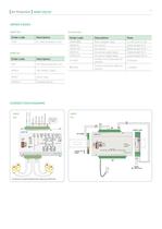
Arc Protection 05 VAMP 120/121 Order codes VAMP 120 Accessories Order code Description Order code Description Note V120 Arc flash protection unit VAMP4RSE VA1DA-6 VA1DA-20 VA1EH-6 VA1EH-20 Trip multiplier relay 4 x NO and 4 x NC Cable length 6 m Cable length 20 m Cable length 6 m Cable length 20 m VAMP 121 Order code Description V121 Arc flash protection unit 3P004 100-240AC / 24DC 3P007 Alarm relay VA1DA-5 Arc sensor Arc sensor Arc sensor (pipe type) Arc sensor (pipe type) Surface mounting plate for sensors Portable sensor VYX001 VYX002 Surface mounting plate for sensors Z-shaped L-shaped…
Open the catalog to page 5

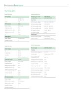
TECHNICAL DATA Power Supply TRIP Contacts Rated voltage Continuous carry Digital Inputs Rated voltage Phoenix type as used Input Data Nominal input voltage Nominal output voltage AC input voltage range DC input voltage range Output Data Nominal output voltage Output current Power Supply Tripping Contacts Rated voltage 250 V ac/dc Breaking capacity DC, when Contact material AgNi Rated voltage Rated current / output Rated current / input Phoenix Type Coil side Nominal input voltage Un Contact type Input voltage range Limiting continuous current 6 A Nominal input current at Uin 9 mA Contact…
Open the catalog to page 7
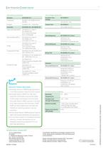
Disturbance standards Power frequency magnetic field Pulse magnetic field Damped oscillatory waves DEVICE TRACK RECORD • Schneider Electric’s VAMP Range specializes in arc flash protection relays for power system • Schneider Electric VAMP’s arc flash fault protection functionality enhances the safety of both people and property and has made Schneider Electric VAMP a pioneer in the field of arc flash protection with more than 10.000 VAMP arc flash systems and units with over 150.000 arc detecting sensors in service • All Schneider Electric VAMP products meet the latest international…
Open the catalog to page 8
В избранное К сравнению

Категория:Oптимальная Arc автономная дуговая защита
Единица измерения:шт
Серия:Arc flash protection
Информация о доставке:
по Москве — 500 Р
Бесплатно
— от 10.000 Р
по России — через ТК СДЭК
.
48 060 ₽
Описание
VAMP 120, подключение 4 датчиков (селективный)
Характеристики
Категория
Oптимальная Arc автономная дуговая защита
Единица измерения
шт
Серия
Arc flash protection
V120 — VAMP 120, подключение 4 датчиков (селективный) отзывы

…
 Удобное оформлениевыбирайте товары и оплачивайте удобными способами
 Бонусная программаСпециальные предложения для дизайнеров и архитекторов
 Гарантия лучшей ценыМы гарантируем самые низкие цены на товары
 Скидки на товарыСкидки на различные группы товаров