-
Contents
-
Table of Contents
-
Troubleshooting
-
Bookmarks
Quick Links
56K USB Modem
User Guide
R46.1999.00
rev 1 5/08
Related Manuals for US Robotics 56K USB Modem
Summary of Contents for US Robotics 56K USB Modem
-
Page 1
56K USB Modem User Guide R46.1999.00 rev 1 5/08… -
Page 3: Table Of Contents
56K USB Modem User Guide Contents Introduction ……….1 Physical Features .
-
Page 4
56K USB Modem User Guide Uninstallation ……… 125 Troubleshooting . -
Page 5
56K USB Modem User Guide 56K USB Modem User Guide U.S. Robotics Corporation 935 National Parkway Schaumburg, Illinois 60173-5157 No part of this documentation may be reproduced in any form or by any means or used to make any derivative work (such as a translation, transformation, or adaptation) without written permission from U.S. -
Page 6
56K USB Modem User Guide… -
Page 7: Introduction
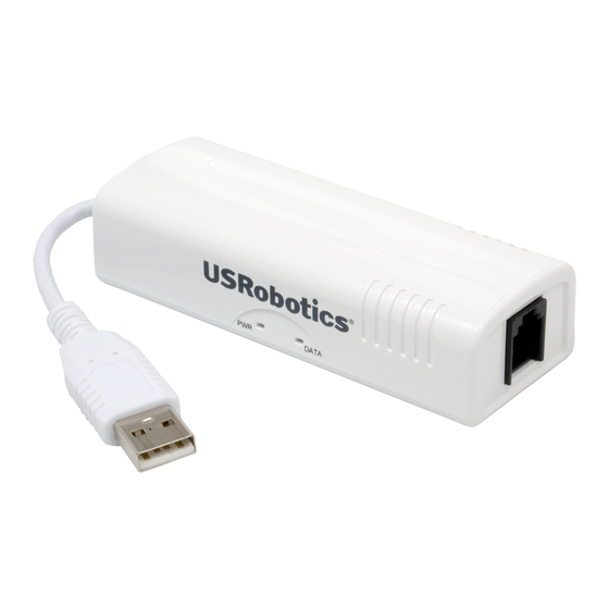
Introduction English The USRobotics 56K USB Modem delivers the performance and reliability USRobotics is known for, in a compact, flexible form factor. This controller-based modem integrates powerful communications processing functions into the modem itself, for assured performance without sapping your computer’s processing power.
-
Page 8: Physical Features
56K USB Modem User Guide Physical Features U S R o b o t i c PW R D A TA Connects the modem to Connects the modem to your your computer. telephone line. State Condition Solid Receiving power and driver is properly installed.
-
Page 9: Installation Instructions
1. Use the provided telephone cord to connect the phone jack on the modem to an analogue telephone wall jack. U S R o To connect a telephone to the same line as the 56K USB Modem for V.92 fea- b o ti cs DAT A tures such as “Modem on Hold”, you will need to use a telephone line splitter…
-
Page 10: Windows Xp
56K USB Modem User Guide 4. When prompted, insert the USRobotics Installation CD-ROM into your CD-ROM drive. If a driver CD was not provided or the driver was downloaded from www.usr.com, browse to the folder where the drivers were downloaded.
-
Page 11: Windows 2000
56K USB Modem User Guide 8. The PWR LED on the modem will light. Congratulations. You have successfully completed the installation procedure. Please register your 56K USB Modem at www.usr.com/productreg/. Windows 2000 You must be logged in as an administrator in order to install this modem.
-
Page 12
56K USB Modem User Guide 3. Double click USRobotics 56K USB Modem.pkg to launch the installer, and follow the on-screen instructions. 4. Go to Apple > System Preferences > Network. If prompted, click OK. 5. Select USB Modem from the Show menu . -
Page 13: Command Reference
56K USB Modem User Guide Command Reference How to Use These Commands USRobotics’ AT command set for controller-based modems consists of commands based on data, FAX, and voice communications. The commands presented in this manual follow the conventions set by ITU-T Recommendation V.250 (05/99), which standardized many of the common AT extensions.
-
Page 14
56K USB Modem User Guide result code. Command Reference — 8… -
Page 15: Sample Command
56K USB Modem User Guide Sample Command E<value>—Command Echo Use this command to instruct the modem to echo characters sent to it. When the echo feature is selected, characters sent to the modem are sent back to the host and displayed on the monitor.
-
Page 16: S Register Conventions
56K USB Modem User Guide S Register Conventions S registers contain parameters used by the modem. The presentation format for an S register is very similar to the format used for an AT command. Each S register has a standard layout consisting of the following: •…
-
Page 17: Synchronous Mode And V.80 At Commands
56K USB Modem User Guide Synchronous Mode and V.80 AT Commands USRobotics’ controller-based modem AT command set supports synchronous command mode and most of the commands defined in ITU-T Recommendation V.80, which defines in-band modem control and synchronous data modes for asynchronous host systems. Recommendation V.80 addresses two types of commands: •…
-
Page 18
56K USB Modem User Guide escape sequence character. A/—Repeat Last Command Use this command to repeat the last AT command. The modem repeats the command currently in the command buffer. Do not use the AT prefix with this command. Do not conclude the command with a terminating character such as enter. -
Page 19
56K USB Modem User Guide C<value>—Carrier Control Controller-based modems support this command to ensure backwards compatibility with communication software that issues the C1 command. However controller-based modems do not support the C0 command. The C0 command may instruct some other modems not to send carrier (i.e., it puts them in receive-only mode). -
Page 20
56K USB Modem User Guide Table 5. Dial Modifiers Dial pause Instructs the modem to pause before processing the next character in the dial string. Register S8 (S8—Pause Time for Comma Dial Modifier on page 98) determines the length of the pause. -
Page 21
56K USB Modem User Guide Table 7. F<value> Commands Online data character echo disabled. H<value>—Hook Control This command instructs the modem to go on-hook to disconnect a call or go off-hook to make the telephone line busy. Result codes: •… -
Page 22
56K USB Modem User Guide Final Receive Carrier Rate 49333 Protocol Negotiation Result LAPM Data Compression Result V42bis Estimated Noise Level Receive Signal Poser Level (–dBm) Transmit Signal Power Level (–dBm) Round Trip Delay (msec) Press any key to continue; ESC to quit… -
Page 23
56K USB Modem User Guide Table 10. ATI11 Command Results(Continued) Result Description Receive Signal Power Level The received signal power, although labeled with units of –dBm, is only a (–dBm) relative measure for comparing calls to/from different locations. This value is valid only during a call. -
Page 24
56K USB Modem User Guide M<value>—Speaker Control Use this command to turn the speaker on and off. Result codes: • OK if <value> = 0—3. ERROR if <value> ≠ 0—3. • Table 12. M<value> Commands Command Function Speaker is off. -
Page 25
56K USB Modem User Guide Table 14. O<value> Commands Issues a rate renegotiation before returning to online data mode. * See +++ Escape Sequence section on page 11. P—Select Pulse Dialing Use this command to configure the modem for pulse dialing. All subsequent D<dial_string> commands use pulse dialing until either the T command or a tone dial modifier is received by the modem. -
Page 26
56K USB Modem User Guide S<register number>=<value>—S Register Control Use this command to view or change an S-register. S-registers contain parameters used by the modem. This command has two forms, one to show the contents of the register and the other to change the contents of the register. -
Page 27
56K USB Modem User Guide W<value>—Result Code Option Use this command to select the modems CONNECT message options. Result codes: • OK if <value> = 0—2. ERROR if <value> ≠ 0—2. • Table 19. W<value> Commands Command Function CONNECT result code reports DTE receive speed. Disables protocol result codes. -
Page 28
56K USB Modem User Guide X<value> Option Result Codes Command Result Codes • • RING • ERROR • CONNECT • NO CARRIER • • RING • ERROR • CONNECT <RATE> • NO CARRIER • • RING • ERROR • CONNECT <RATE>… -
Page 29
56K USB Modem User Guide Z<value>—Reset and Recall Stored Profile Use this command to make the modem go on-hook and restore the profile saved by the last &W command. Note: Both Z0 and Z1 restore the same profile (see &W<value>—Store Current Configuration on page 28). -
Page 30
56K USB Modem User Guide &D<value>—Data Terminal Ready (DTR) Control Use this command to select the modem’s response to the data terminal ready (DTR) signal. The host system generates the DTR signal and supplies it to the modem. Result codes: •… -
Page 31
56K USB Modem User Guide Table 28. &G<value> Commands Command Function &G0 Disables guard tone (default). &G1 Selects 550 Hz guard tone. &G2 Selects 1800 Hz guard tone. &J<value>—Auxiliary Relay Option This command is supported to ensure backward compatibility with communications software that issues the J0 command. -
Page 32
56K USB Modem User Guide &P<value>—Pulse Dial Make-to-Break Ratio Selection Use this command to select the make-to-break ratio. This command is effective only for Japan. Result codes: • OK if <value> = 0—2. ERROR if <value>n ≠ 0—2. • Table 32. &P<value> Commands for Domestic Versions… -
Page 33
56K USB Modem User Guide &T<value>—Self-Test Commands Use this command to perform diagnostic tests on the modem. Each test is designed to isolate a problem location when experiencing periodic data loss or random errors. Result codes: • OK if <value> = 0. -
Page 34
56K USB Modem User Guide Blind Dial Pause 2 sec NoAnswer Timeout 50 sec «,» Pause Time 2 sec Press any key to continue; ESC to quit. Option Selection AT Cmd No Carrier Disc 2000 msec DTMF Dial Speed 95 msec… -
Page 35
56K USB Modem User Guide &Z<location>=<stored_number>—Store Telephone Number Use this command to store a dialing string. Controller-based modems can save four dialing sting. The format for the command is &Z<storage_location> = <dialing_string>. The dial string may contain up to 40 characters. The ATDS=<storage_location> command (D<dial_string>—Dial on page 13) dials using the stored string. -
Page 36
56K USB Modem User Guide Table 39. G<value> Commands Command Function The modem processes XON/XOFF flow control characters locally (default). The modem passes XON/XOFF flow control characters. J<value>—Adjust Bits/s Rate Control Use this command to specify whether or not the negotiated connect speed of the modem forces the adjustment of the speed of the DTE to the modem’s speed. -
Page 37
56K USB Modem User Guide In the third case, the modem receives a break from a remote modem during a connection. These commands are shown in Table 43. Table 43. K<value> Commands When Break Is Received During Connection Command Function K0, K1 Clears data buffers and sends a break to the DTE. -
Page 38
56K USB Modem User Guide R<value>—Ring Indicator Signal Off After Answer This command is supported to ensure backward compatibility with communications software that issues the R0 command. The R1 version of this command is not supported. Result codes: • OK if <value> = 0. -
Page 39
56K USB Modem User Guide X<value>—XON/XOFF Pass Through Use this command to restrict the XON/XOFF flow control to the local DCE for processing or have the local DCE send the flow control characters to the remote DCE. Result codes: •… -
Page 40
56K USB Modem User Guide Table 51. -V90=<value> Commands -V90=5 Selects 32000 bits/s. -V90=6 Selects 33333 bits/s. -V90=7 Selects 34666 bits/s. -V90=8 Selects 36000 bits/s. -V90=9 Selects 37333 bits/s. -V90=10 Selects 38666 bits/s. -V90=11 Selects 40000 bits/s. -V90=12 Selects 41333 bits/s. -
Page 41
56K USB Modem User Guide Table 52. %C<value> Commands Command Function V.44/V.42bis/MNP 5 disabled. No data compression. V.44/V.42bis/MNP 5 enabled. Data compression enabled (default). %E<value>—Auto Fallback/Fallforward Control This command provides the option for the modem to automatically monitor line quality, to fall back when line quality is insufficient, and to fall forward when line quality is sufficient. -
Page 42
56K USB Modem User Guide Table 56. Valid <v8cf> Values Value Meaning Enables DCE-controlled V.8 origination negotiation. Enables DCE-controlled V.8 origination negotiation, issues +A8x indications. Table 57. Valid <v8b> Values Value Meaning Disables V.8 negotiation. Enables DCE-controlled V8bis negotiation (default). -
Page 43
56K USB Modem User Guide Table 60. Valid <sig_en> Values Value Meaning Enables detection of initiation signals (default). Enables detection or responding signals. Table 61. Valid <msg_en> Values Value Meaning Disables detection of messages (default). Enables detection of V.8bis messages. -
Page 44
56K USB Modem User Guide Table 66. +DCS Extended Syntax Commands Command Description +DCS=<v42bis>,<v44> Configures compression algorithms. +DCS? Displays the current data compression configuration. +DCS=? Displays the valid +DCS parameter values. +DR<value>—Data Compression Reporting Use this command to enable or disable the compression report. If the compression report is enabled, the +DR:<type>… -
Page 45
56K USB Modem User Guide Table 70. Valid <direction> Values Value* Meaning Does not negotiate V.42bis compression. Modem accepts V.42bis compression in both direction (default). * ITU-T Recommendation V.250 (05/99) standardized this command. The standard command includes two additional parameter val- ues (1 and 2), which are not supported by the controller-based AT command set. -
Page 46
56K USB Modem User Guide Table 73. Valid <max_codewords_tx> and <max_codewords_rx> Values Value Meaning 1024 Default <max_codewords_tx> and <max_codewords_rx> value. 256—2048 Valid transmit and receive code word settings. The <max_string_tx> parameter specifies the maximum string length to negotiate in the transmit direction. -
Page 47
56K USB Modem User Guide ERROR if <break_selection> ≠ 0—3 or <timed> ≠ 0 or <default_length> ≠ 10—90 in increments of 10. • Table 77. Valid break_selection Values Value Meaning Ignore break (default). Nonexpedited, nondestructive. Expedited, nondestructive. Expedited, destructive. Table 78. +EB Extended Syntax Commands… -
Page 48
56K USB Modem User Guide Table 81. +ER Error Control Reporting Intermediate Result Codes Command Function +ER: NONE Data compression not in use. +ER: LAPM V.42 LAPM protocol is in use. +ER: ALT V.42 alternative protocol is in use. Table 82. +ER Extended Syntax Commands… -
Page 49
56K USB Modem User Guide +ESA=<trans_idle>,<frame_idle>,<framed_un_ov>,<hd_auto>,<crc_type>,<nrz i_en>,<syn1>—Set Up Error Control Parameters Use this command to set the control parameters for the DCE in synchronous access mode (see page 11). USRobotics host-based modems do not use the <framed_un_ov>, <hd_auto>, and <syn1> parameters. -
Page 50
56K USB Modem User Guide +ETBM=<pending_TD>,<pending_RD>,<timer>—Call Termination Buffer Manage- ment Use this command to set the behavior of the modem upon call termination. Only +ETBM=0,0,0 is a valid combination. This means that the modem discards all the buffered data when the call is terminated. -
Page 51
56K USB Modem User Guide +GCAP—Request Complete Capabilities List Use this command to display the modems supported capabilities. The +GCAP command is an action command that always generates an OK result code and does not have extended syntax. The valid responses are shown in Table 91. -
Page 52
56K USB Modem User Guide +GMM—Modem Identification Use this command to display the modem identity string and driver version number. The modem returns the same result codes as those generated by the I0 or I3 commands. Result codes: • OK for all extended syntax forms of this command. -
Page 53
56K USB Modem User Guide Table 97. +IFC Extended Syntax Commands +IFC=? Displays the supported local flow control parameter settings. +ILRR=<value>—DTE-DCE Local Rate Reporting Use this command to display or hide the local rate report result code. If the rate report is enabled, the reported <rate>… -
Page 54
56K USB Modem User Guide Table 100. +IPR Commands +IPR=115200 115200 bits/s. Table 101. +IPR Extended Syntax Commands Command Description +IPR=<DTE rate> Sets the DTE to DCE transmission rate. +IPR? Displays the current DTE to DCE transmission rate. +IPR=? Displays all supported transmission rates. -
Page 55
56K USB Modem User Guide Table 104. +MR Extended Syntax Commands Command Description +MR=<value> Selects or deselects transmission of the modulation result codes. +MR? Displays the current status of the modulation report result code. +MR=? Displays the supported parameter values for modulation rate reporting. -
Page 56
56K USB Modem User Guide The <max_rate> specifies the highest connections rate for the DCE. Table 107. Valid <max_rate> Range Value Meaning 31200 Determined by modulation selected in <carrier> (default). 300—56000 Value limited by modulation selected in <carrier>. Table 108. Valid <max_rate> for Each <carrier>… -
Page 57
56K USB Modem User Guide +PCW=<call_waiting>—Call Waiting Enable Use this command to select how the modem responds to a call waiting signal. The controller-based response is also dependent on the current setting of the caller ID command, +VCID (+VCID=<pmode>— Caller-ID on page 77). -
Page 58
56K USB Modem User Guide Result codes: • OK if <value> = 0, 1 ERROR if <value> ≠ 0, 1 • Table 116. Valid +PMH Parameter Values Value Meaning +PMH=0 Enables modem on hold. +PMH=1 Disables modem on hold (default). -
Page 59
56K USB Modem User Guide during a modem on-hold procedure. In particular, bits 16—19 of the sequence define hold time. The +PMHR command does not have any extended syntax command forms. Result codes: • OK if the modem on-hold request is granted. -
Page 60
56K USB Modem User Guide Table 119. Valid +PMHT Commands +PMHT=7 Grants modem on-hold request with a 3 min. time-out. +PMHT=8 Grants modem on-hold request with a 4 min. time-out. +PMHT=9 Grants modem on-hold request with a 6 min. time-out. -
Page 61: Fax Commands
56K USB Modem User Guide +PSS=<value>—Use Short Sequence Use this command to enable or disable the V.92 short training sequence. Result codes: • OK if <value> = 0. ERROR if <value> ≠ 0. • Table 123. Valid +PSS Commands Command…
-
Page 62
56K USB Modem User Guide Table 125. +FAA Commands +FAA=1 The DCE can answer and automatically determine whether to answer as a facsimile DCE or as a data modem. Table 126. +FAA Extended Syntax Commands Command Description +FAA=<value> Enables or disables adaptive answer. -
Page 63
56K USB Modem User Guide +FBO=<value>—Phase C Data-Bit Order and Phases B and D Data-Bit Order This command is used to by DCE to offer service to convert Phase C and Phase B/D data bit order transparently to the DTE and remote facsimile. A direct mapping means the first bit transferred of each octet on the DTE-DCE link is the first bit transferred on the PSTN line. -
Page 64
56K USB Modem User Guide (wd), page length (ln), data compression format (df), error correction (ec), file transfer mode (bf), scan time/ line (ST), and JPEG for color and black and white (jp). Result codes: • OK if <vr> = 000-0FF, <br> = 00-0D,<wd> = 00-02, <ln> = 00-02, <df> = 00-03, <ec> = 00-01, <bf> = 00, <st>… -
Page 65
56K USB Modem User Guide Table 132. +FCC Valid Parameter Values(Continued) Label Values Description Label Values Description A4, 297 mm Disable JPEG coding B4, 364 mm Enable JPEG coding (Rec. T.81) Unlimited length (default) Full color mode Enable preferred Huffman tables… -
Page 66
56K USB Modem User Guide Table 134. +FCLASS Extended Syntax Commands Command Description +FCLASS=<value> Selects the class or mode of the modem. +FCLASS? Displays the current class or mode. +FCLASS=? Displays the available parameter values for the +FCLASS command. +FCO—Facsimile Connection A +FCO response from DCE to DTE indicates a connection with a facsimile station. -
Page 67
56K USB Modem User Guide Table 136. +FCR Extended Syntax Commands +FCR=<value> Controls capability to receive message data. +FCR? Displays the current receive message data capability. +FCR=? Displays all available parameter values. The DCE returns (00,01). +FCS—DCE Reports the DCS Frame Information A +FCS response from DCE to DTE reports the digital command signal (DCS) frame information. -
Page 68
56K USB Modem User Guide +FDT—Data Transmission Request A +FDT command from DTE requests the DCE to transmit a Phase C page. This command is issued at the beginning of every page. If DCE receives command during Phase B, it proceeds with negotiation and releases the DCS message to the remote facsimile. -
Page 69
56K USB Modem User Guide Table 139. HSC Codes(Continued) HSC Code Hangup Cause Description Unspecified transmit Phase B error Remote cannot receive or send COMREC error in transmit Phase B COMREC invalid command received RSPREC error DCS sent three times without response DIS/DTC received 3 times;… -
Page 70
56K USB Modem User Guide +FHR—Report Received HDLC Frame +FHR:<received HDLC frame octets> reports the HDLC data that was sent by the DCE. Result codes: • +FHT—Report Transmitted HDLC frame +FHT:<transmitted HDLC frame octets> reports the HDLC data that was received by the DCE. -
Page 71
56K USB Modem User Guide Table 140. +FLI Extended Syntax Commands Command Description +FLI=<local ID string> Local ID string. +FLI? Displays the range of character values supported. +FLI=? Displays the range of character values supported. +FLO=<value>—Flow Control Selection Use this command to set the type of flow control used to transmit data between the host and the modem. -
Page 72
56K USB Modem User Guide +FMI?—Manufacturer Identification This command returns: • U.S. Robotics Result codes: • This command always yields an OK result code. Table 144. +FMI Extended Syntax Command Description +FMI, +FMI? Displays the modem manufacturer identification. +FMM—Product Identification This command returns the product identification, depending on the product. -
Page 73
56K USB Modem User Guide +FMS=<value>—Minimum Phase C Speed Control Use this command to limit the lowest negotiable speed for a session. The value is the same as the BR parameter in the +FCC valid parameter table. Result codes: •… -
Page 74
56K USB Modem User Guide +FNR—Negotiation Message Reporting Control Parameter +FNR=<rpr>,<tpr>,<idr>,<nsr> is used to control the reporting of messages generated during Phase B negotiations. Description of controls is shown in table below. Result codes: • OK if <rpr> = 0-1, <tpr> = 0-1,<idr> = 0-1, <nsr> = 0-1. -
Page 75
56K USB Modem User Guide +FPA—Selective Polling Address The +FPA:<selective polling address string> is a 20-digit ASCII string in the range from 0x20—0x7E. This string is sent by the DCE at the time specified by the T.30 recommendation, as long as parameter is not null. -
Page 76
56K USB Modem User Guide Table 153. +FPP Extended Syntax Commands Command Description +FPP=<value> DCE to DTE packet protocol setting. Disabled only setting supported. +FPP? Displays the current setting for packet protocol. +FPP=? Displays the available parameter values for the +FPP command. -
Page 77
56K USB Modem User Guide +FPW—Sending or Polling Password The +FPW:<PassWord string> is a 20-digit ASCII string in the range from 0x20—0x7E. This string is sent by the DCE at the time specified by the T.30 Recommendation, as long as parameter is not null. -
Page 78
56K USB Modem User Guide +FRM=<mod>—Receive Data Use the +FRM command to instruct the modem to received data using the modulation defined by Table 160. Result codes: • CONNECT if <mod> = 3, 24, 48, 72—74, 96—98, 121, 122, 145, 146, and the connection is estab- lished. -
Page 79
56K USB Modem User Guide +FRQ—Receive Quality Threshold This +FRQ=<pgl>,<cbl> command is used to decide if copy quality is OK. This decision is made based on the percentage of good lines (pgl) and the consecutive bad line count (cbl). The USRobotics FAX modem supports this command only for MH encoding. -
Page 80
56K USB Modem User Guide +FSA—Destination Subaddress The +FSA:<destination subaddress string> is a 20-digit ASCII string in the range from 0x20—0x7E. This string is sent by the DCE at the time specified by the T.30 Recommendation, as long as parameter is not null. -
Page 81
56K USB Modem User Guide +FTI—DCE Reports Received Transmit Station ID (TSI) A +FTI response from DCE to DTE reports the identification of the transmitting facsimile. The syntax of the response is as follows: +FTI: <TSI ID string>, where TSI ID string is the remote facsimile’s identification. The string is limited to 20 characters in range from 0x20—0x7E. -
Page 82
56K USB Modem User Guide +FTM=<mod>—Transmit FAX Data with <mod> Carrier +FTM=<mod> command causes the modem to transmit data using the modulation defined by Table 169. Result codes: • CONNECT if <mod> = 3, 24, 48, 72—74, 96—98, 121, 122, 145, 146, and the connection is estab- lished. -
Page 83: Voice Commands
56K USB Modem User Guide Voice Commands The AT voice command set follows ITU-T Recommendation V.253. The commands are sent through the com port, but the data path is sent either through the com port or through a DMA channel using the wave driver.
-
Page 84
56K USB Modem User Guide +VDR=<enable>,<report>—Distinctive Ringing and Cadence Report Use this command to enable or disable the distinctive ringing feature. Distinctive ringing features are identified by the DROF=<length of ring in 0.1 s increments> and DRON=<length of silence in 0.1 s increments>… -
Page 85
56K USB Modem User Guide Table 176. +VGM Extended Syntax Commands Command Function +VGM=<gain> Sets the microphone gain level. +VGM? Displays the current gain level. +VGM=? Displays the supported speaker gain levels for the product. +VGR=<gain>—Receive Gain Selection Use this command to set the receive microphone gain control. The receive gain has a range of 0—255. -
Page 86
56K USB Modem User Guide Table 179. +VGS Command <gain> Values Command Function <gain> = 128 Nominal level for speaker gain (default). <gain> = a value greater than 128 Increases gain above nominal level. <gain> = a value less than 128 Decreases gain below nominal level. -
Page 87: Voice Commands: Speakerphone Operation
56K USB Modem User Guide Table 183. +VIT Extended Syntax Commands Command Function +VIT=<timer> Sets the DTE/DCE inactivity timer. +VIT? Displays the current value of the timer. +VIT=? Displays the range of supported delay times in seconds. +VNH=<Hook>—Automatic Hang-Up Control Use this command to enable or disable automatic DCE hang-ups in the data and facsimile modes.
-
Page 88: Voice Commands: Telephone Answering Device (Tad)
56K USB Modem User Guide Table 187. +VLS Extended Syntax Commands Command Function +VLS=<value> Attaches or detaches an analog source or destination to the system in voice mode. +VLS? Reports the current analog source/destination configuration, along with a listing of all event codes reported from the modem to the DTE under that configuration.
-
Page 89
56K USB Modem User Guide Events Reported to the DTE The modem returns OK when going off-hook in voice mode (+FCLASS=8). After answering in voice mode, the modem may send any of the following <DLE> shielded event codes to the DTE, as appropriate. -
Page 90
56K USB Modem User Guide +VRA=<interval>—Ringing Tone Goes Away Timer Use this command to set the ringing tone goes away timer before originating a call. The ringing tone goes away timer defines the amount of time the modem waits between ringing tones before assuming that the remote station has gone off-hook. -
Page 91
56K USB Modem User Guide +VSD=<sds>,<sdi>—Silence Detection (QUIET and SILENCE) Use this command to set the silence detection sensitivity (<sds>) and silence detection interval (<sdi>). The <sds> parameter defines the line noise sensitivity level in decibels. The <sdi> parameter specifies the amount of time the modem waits before reporting silence to the DTE. It is used for determining the presumed hang-up (SILENCE), after which the modem sends <DLE>-s to the… -
Page 92
56K USB Modem User Guide Table 196. +VSM Extended Syntax Commands +VSM? Returns the numeric and string labels of the compression method currently in use, and the sampling rate currently in use. AT+VSM=? Reports the voice compression methods supported by the DCE and the voice sampling rates at which they are supported. -
Page 93
56K USB Modem User Guide +VTR—Start Voice Transmission and Reception Process Use this command to initiate full-duplex voice mode* in the DCE. In this mode, the DTE selects the analog source and sink through the +VLS command; the selections can be microphone and speaker or GSTN. -
Page 94: Fast Connect And V23 Reverse Channel Commands
56K USB Modem User Guide +VTX—Enter Voice Transmit Data State Use this command to initiate the voice transmission process with the voice stream sent through the comm port. Applications using the wave interface do not use the +VTX command. There are two ways for the DCE to leave the voice transmit state: •…
-
Page 95
56K USB Modem User Guide Table 203. Register S109 Description S109[1:0] = 00 S109[1:0] = 01, 10, 11 S109[2] = 1 Fast connect Phase 1 enable S109[3] = 1 PCM upstream enable S109[4] = 1 V.92 enable S109[5] = 1… -
Page 96
56K USB Modem User Guide Table 204. #UD Last Call Status Report Format Note: Refer to Table 1 in the Microsoft specification. Value(s) Required Definition Implemented 2 digits Diagnostic command specification revision number, digit.digit. 0—A Call setup result code. Table 205 on page 92. -
Page 97
56K USB Modem User Guide Table 204. #UD Last Call Status Report Format(Continued) Note: Refer to Table 1 in the Microsoft specification. Value(s) Required Definition Implemented 4 digits 0—FA00 Final transmit carrier rate. 4 digits 0—FA00 Final receive carrier rate. -
Page 98
56K USB Modem User Guide Table 204. #UD Last Call Status Report Format(Continued) Note: Refer to Table 1 in the Microsoft specification. Value(s) Required Definition Implemented 2 digits 0—FF Call waiting event count. 62— — — Reserved for future versions of the specification. -
Page 99
56K USB Modem User Guide Table 206. gstnModulationSchemeActive from 3.7.2/V.58 Note: Refer to Table 6 in the Microsoft specification. V.pcm (symmetric). — E—7F Reserved (V.58). — — K56flex. V.FC. — V.32terbo. — 80-FF Reserved for mfgs. — Table 207. errorControl Active from 3.5.2/V.58 Note: Refer to Table 7 in the Microsoft specification. -
Page 100
56K USB Modem User Guide Table 210. callCleared Codes from 3.6.4/V.58-1994 Note: callCleared indicates that the DCE has gone on-hook and that the previously existing network con- nection has been cleared. These values are hexadecimal, converted from decimal in V.58. Refer to Table 10 in the Microsoft specification. -
Page 101: S-Registers
56K USB Modem User Guide Table 210. callCleared Codes from 3.6.4/V.58-1994(Continued) Note: callCleared indicates that the DCE has gone on-hook and that the previously existing network con- nection has been cleared. These values are hexadecimal, converted from decimal in V.58. Refer to Table 10 in the Microsoft specification.
-
Page 102: S-Register Definitions
56K USB Modem User Guide Table 212. S-Register Summary(Continued) Register Description Range Unit Default Results bit-mapped options status. — — V.34 modulation enable/disable. 0—1 — V17 disable. 0—1 On/Off Inactivity timer. 0—255 Minutes Synthetic ring volume. 0—255 Synthetic ring frequency.
-
Page 103: S1 Ring Counter
56K USB Modem User Guide S1—Ring Counter The modem increments the S1 register each time it detects a ring signal on the telephone line. The modem clears S1 if no rings occur over a six second interval. This register is read-only.
-
Page 104: S5 Command-Line Editing Character
56K USB Modem User Guide S5—Command Line Editing Character (User Defined) S5 sets the character recognized as a backspace (pertains to asynchronous operation only). The modem does not recognize the backspace character if it is set to a value that is greater than 32 ASCII. This character can be used to edit a command line.
-
Page 105: S10 Automatic Disconnect Delay
56K USB Modem User Guide S9—DTMF Tone Off Duration This register determines the number of ms that the DTMF tone is off. Refer to the USRobotics Controller- Based Homologation Manual for specific country defaults. Note: This register default is set to the same as S11 register upon reset.
-
Page 106: S18 Dial-Pulse Interdigit Period
56K USB Modem User Guide Table 213. Register S14 Bits Description Value Result codes (V <value>). 0 = Numeric (V0). 1 = Verbose (V1) (default). Pulse dial pulses/s selection (&Pn). 0 = 10 pulses/s (&P0 and &P1) (default). 1 = 20 pulses/s (&P2).
-
Page 107
56K USB Modem User Guide S28—V.34 Modulation Enable/Disable This register enables/disables V.34 modulation. Range: 0—1. • Default: 1. Table 216. S28 Values Value Function Disables V.34 modulation. Enables V.34 modulation. S30—Inactivity Timer This register specifies the length of time in minutes that the modem must wait before disconnecting when no data is sent or received. -
Page 108
56K USB Modem User Guide S35—Data Calling Tone Data calling tone is a tone of a certain frequency and cadence as specified in V.25, which allows remote data/FAX/voice discrimination. The frequency is 1300 Hz with a cadence of 0.5 s on and 2.0 s off. The setting of the homologation parameter 1f, calling tone flag, determines if S35 (same as -C command) is enabled. -
Page 109
56K USB Modem User Guide S38—56K Downstream Rate Once a connection type* (V.90) is determined, use register S38 to force a particular downstream rate. A value of zero disables both connection types and allows a more reliable V.34 connection. The default value of one allows the modem to select the downstream rate automatically. -
Page 110
56K USB Modem User Guide (48 kbits/s – 4 kbits/s). The exception to this is for 32 kbits/s and 34 kbits/s rates, which are the true rates regardless of the number of RBS frames detected. S42—Auto Rate This command is used for testing and debugging only. -
Page 111
56K USB Modem User Guide Table 224. Register S36 and S48 Configuration Settings S36 = 0, 2 LAPM or hang-up. Do not use. S36 = 1, 3 LAPM or asynchronous. Asynchronous. S36 = 4, 6 LAPM, MNP, or hang-up. MNP or hang-up. -
Page 112
56K USB Modem User Guide Range: 6—25 (corresponding to –6 dBm to –25 dBm transmit level) • Default: 10 (–10 dBm transmit level) • Units: –dBm S127—Caller ID Impedance Activation Register S127 invokes the Caller ID impedance specifications for a particular country. -
Page 113: Result Codes
56K USB Modem User Guide Result Codes The modem’s AT command handler responds to commands from the caller and to activity on the line via result codes. Table 225 presents a summary of these result codes. Two forms of each result code are available. The long-form, or verbose, response is given when V1 is selected, and the short-form, data-like numeric response is given when V0 is selected.
-
Page 114
56K USB Modem User Guide Table 225. Result Code Summary (continued) Numeric Result Code Description Code DELAYED Delay is in effect for the dialed number. BLACKLISTED Dialed number is blacklisted. BLACKLIST FULL Blacklist is full. CONNECT 32000 EC* Connection at 32000 bits/s. -
Page 115: Voice Modem Command Examples
56K USB Modem User Guide Voice Modem Command Examples The application issues AT commands to request actions by the modem, and the modem responds with standard TIA-602 result codes to tell the application that the requested action has been completed.
-
Page 116: Example #1: Initiating A Speakerphone Call (With Phone Muting During Conversation)
56K USB Modem User Guide Example #1: Initiating a Speakerphone Call (with Phone Muting Dur- ing Conversation) The speakerphone application is loaded. The modem is initially idle in data mode. The user then decides to pick up the phone to place a speakerphone call. Picking up the phone should initiate the following chain of events.
-
Page 117: Example #2: Initiating A Stored Number Speakerphone Call
56K USB Modem User Guide Example #2: Initiating a Stored Number Speakerphone Call The speakerphone application is loaded. The modem is initially idle in data mode. The user then decides to place a speakerphone call either by entering the number without first going off-hook or by selecting a number previously stored in the application.
-
Page 118: Example #4: Receiving An Incoming Fax Call In Speakerphone Or Tad Mode And Switching To Fax Mode
56K USB Modem User Guide Command/Response Description AT+VLS=7 Call is answered. Attach internal speaker and microphone to the line, DCE off-hook. DCE responds. Now in speakerphone mode, connected to the line (call is answered). The speakerphone user picks up the phone and hears the caller from the other end. Conversation continues for awhile.
-
Page 119: Example #5: Receiving An Incoming Data Call In Speakerphone Or Tad Mode And Switching To Data Mode
56K USB Modem User Guide Example #5: Receiving an Incoming Data Call in Speakerphone or TAD Mode and Switching to Data Mode In this example, the sequence begins at the point of the user or telephone answering device (TAD) taking the speakerphone off-hook and detecting a data calling tone from the other end.
-
Page 120
56K USB Modem User Guide AT+VSD=128,0 DTE selects normal silence detection sensitivity, and a silence detec- tion interval of 0 seconds. Disables silence detection. DCE responds. <DLE>-R DCE detects another ring and notifies DTE. AT+VLS=1 The modem answers the call. -
Page 121: Example #8: Call Screening And Recording A Message With Tad Using The Wave Driver To Transmit And Receive Voice Samples
56K USB Modem User Guide Example #8: Call Screening and Recording a Message with TAD Using the Wave Driver to Transmit and Receive Voice Samples In this example, the TAD application is loaded. The modem is in data mode (+FCLASS=0), idle state.
-
Page 122: V.22 Fast Connect Command Example
56K USB Modem User Guide At the end of the message, the application may issue the WAVE_IN_STOP message to the wave driver. Command/Response Description DTE issues standard command to terminate call. DCE goes on-hook, speaker and microphone are detached from system, and modem returns to data mode (+FCLASS=0).
-
Page 123: At Command Cross-Reference Tables
56K USB Modem User Guide AT Command Cross-Reference Tables Table 227. Data and General Commands Command Description Reference* Repeat last command. — Answer. V.250 (05/99) Communication standard setting. — Carrier control. — Dial. V.250 (05/99) Echo command. V.250 (05/99) Online data character echo command.
-
Page 124
56K USB Modem User Guide Table 227. Data and General Commands Modem port flow control. — Adjust bits/s rate control. — * All references are ITU-T recommendations unless otherwise noted. Table 227. Command Description Reference* Adjust bits/s rate control. —… -
Page 125
56K USB Modem User Guide Table 228. V.92 and V.44 Commands Reference* Command Function +DCS Select data compression algorithm V.250 +DS44 V.44 data compression V.250 +PCW Call waiting enable V.250 +PIG PCM upstream ignore V.250 +PMH Modem on-hold enable V.250… -
Page 126
56K USB Modem User Guide Table 229. FAX Class 1/Class 1.0/Class 2/Class 2.0/2.1 Commands Summary(Continued) Reference Command Function +FIT DTE inactivity timer (not supported T.32 (08/95) +FKS Session termination command T.32 (08/95) +FLI DCE transmits local ID string, TSI or CSI —… -
Page 127
56K USB Modem User Guide Table 230. AT Voice Commands Summary Command Description Reference* +FCLASS=8 Enter voice mode. V.253 (02/98) +VCID Caller-ID. V.253 (02/98) +VDR Distinctive ring. V.253 (02/98) +VEM Event reporting and masking. IS-101 +VGM Microphone gain. — +VGR Receive gain selection. -
Page 128
56K USB Modem User Guide Table 231. T.35 Country Code Table(Continued) TAPI Code T.35 Code Used in +GCI Modem Internal CountryID Country (decimal) (hex) (hex) Belgium Bolivia Bosnia — Brunei — Bulgaria Cabo Verde (Cape Verde) — Cambodia — Canada —… -
Page 129
56K USB Modem User Guide Table 231. T.35 Country Code Table(Continued) TAPI Code T.35 Code Used in +GCI Modem Internal CountryID Country (decimal) (hex) (hex) India Indonesia Iran — Ireland Israel Italy Japan Jordan — Kenya — Kuwait Latvia Lebanon… -
Page 130
56K USB Modem User Guide Table 231. T.35 Country Code Table(Continued) TAPI Code T.35 Code Used in +GCI Modem Internal CountryID Country (decimal) (hex) (hex) Saudi Arabia — Serbia — Seychelles — Singapore Slovakia Slovenia South Africa South Korea Spain… -
Page 131: Uninstallation
56K USB Modem User Guide Uninstallation Note:These instructions only apply to this USRobotics modem. If the modem you’ll be uninstalling was made by another manufacturer or is an another USRobotics modem, refer to that modem’s docu- mentation for instructions. Windows Vista 1.
-
Page 132
56K USB Modem User Guide Windows 2000 1. Click Windows Start > Settings > Control Panel and double-click System. 2. Click the Hardware tab and click the Device Manager button. 3. Double-click to expand Modems. 4. Right-click U.S. Robotics V.92 USB Modem and select Uninstall. To confirm the removal of the device from your system, click OK. -
Page 133: Troubleshooting
56K USB Modem User Guide Troubleshooting General This procedure addresses a number of symptoms that you might experience with your modem. 1. Verify that the cables are connected correctly. This includes all cables connecting the telephone line, the modem, and your computer.
-
Page 134: My Pwr Led Is Not Lit
C. Select the Modem tab. D. Verify that USRobotics 56K USB Modem is shown as your current modem. If the modem is not selected; scroll through the Modem list, select USRobotics 56K USB Modem and click Apply Now. If the installation was still not successful; repeat the installation procedure making sure you plug the modem directly in to a USB port on your computer.
-
Page 135
56K USB Modem User Guide Solution 2: When you insert or remove a USB cable from your computer, the computer should indicate activity such as hard disk activity or an hourglass cursor. If the computer does not show any sign of activity, your system may not be properly communicating with the USB ports. -
Page 136: My Communication Software Does Not Recognize The Modem
56K USB Modem User Guide My communication software does not recognize the modem. Solution 1: Your communication software may not function properly if any of the following are true: • More than one version of the software is installed on your computer.
-
Page 137: My Modem Doesn’t Dial Out Or Doesn’t Answer Incoming Calls
56K USB Modem User Guide My modem doesn’t dial out or doesn’t answer incoming calls. Solution 1: You may have a bad telephone cord. Try another telephone cord. Solution 2: You may have plugged the modem’s phone cord into a digital line. Contact the department responsible for your phone system if you are unsure whether your phone line is analogue or digital.
-
Page 138: My Modem Is Not Achieving A 56K Internet Connection
56K USB Modem User Guide My modem is not achieving a 56K Internet connection. Solution 1: Contact your ISP to verify that the number you are dialling supports V.90/V.92 speeds. Solution 2: Contact your telephone company to verify that the telephone line for your modem supports V.90/V.92 speeds.
-
Page 139: Additional Information
3. Many of the most common difficulties that users experience have been addressed in the FAQ and Troubleshooting Web pages for your 56K USB Modem. The Support pages also contain current sup- port contact information and documentation. 4. The support contact information on the last page of this guide.
-
Page 140: Radio And Television Interference
56K USB Modem User Guide Radio and Television Interference: This equipment has been tested and found to comply with the limits for a Class B digital device, pursuant to Part 15 of the FCC Rules. These limits are designed to provide reasonable protection against harmful interference in a residential installation.
-
Page 141: Ul Listing/Cul Listing
56K USB Modem User Guide disconnect the equipment until the problem is resolved. There are no serviceable parts in this equipment. If your home has specially wired alarm equipment connected to the telephone line, ensure the installation of this equipment does not disable your alarm equipment. If you have questions about what will disable alarm equipment, consult your telephone company or a qualified installer.
-
Page 142: Ce Compliance
We, U.S. Robotics Corporation of 935 National Parkway, Schaumburg, Illinois, 60173-5157 USA, declare under our sole responsibility that the product, USRobotics 56K USB Modem, Model 5637, to which this declaration relates, is in conformity with the following standards and/or other normative documents.
-
Page 143: Support
56K USB Modem User Guide Support Support / Assistance / Servizio assistenza / Asistencia técnica / Destek / Υποστήριξη 1. USRobotics: www.usr.com/support/ Model Number Serial Number 5637-OEM United States www.usr.com/emailsupport (888) 428-9450 Canada www.usr.com/emailsupport (888) 428-9450 Austria / Österreich / Ausztria www.usr.com/emailsupport/de 07110 900 116…
-
Page 144
56K USB Modem User Guide…
-
Contents
-
Table of Contents
-
Bookmarks
Quick Links
56K Se rial Contro ller
Faxmodem
Quick Installation Guide
Guid e d ‘i nst allatio n rap ide
I n s ta l l a ti o n s a n le i t u n g
Guida per l’installazione rapida
Guía breve de instalación
Př íru čka p ro rych lou insta laci
Snabbinstalla tionsguide
Краткое руководст во п о уст ан ов к е
Installa sjonsveiledning
H ı z l ı K u r u l u m K ı l a v u z u
R24.0783.00
rev 1.2 10/09
Summary of Contents for US Robotics 56K SERIAL CONTROLLER FAXMODEM
This manual is also suitable for:
5630g
 Loading…
![]()
This manual covers installation and operating instructions for the following U.S. Robotics modems:
∙ Sportster Voice 56K internal and external modems
U.S. Robotics, the USRobotics logo, and Sportster are registered trademarks and Connections, Total Control, Courier, RapidComm, x2, and the x2 logo are trademarks of U.S. Robotics. Windows is a registered trademark of Microsoft Corp. CompuServe is a registered trademark of CompuServe Inc. America Online is a registered trademark of America Online Inc. Any other trademarks, trade names, service marks, or service names owned or registered by any other company and used in this manual are the property of their respective companies.
© 1997 U.S. Robotics
7770 North Frontage Road
Skokie, IL 60077-2690
All Rights Reserved
IMPORTANT! This modem is 56Kbps capable. However, current FCC rules limit download speeds to 53Kbps. See page 3 for details.

TABLE OF CONTENTS
|
U.S. Robotics: The Intelligent Choice in Information Access |
1 |
|
Welcome to x2 Information Access |
2 |
|
Product Features |
4 |
|
Read This First! |
6 |
|
Part I — Internal Modem Installation |
6 |
|
Section A: Internal Modem Installation with Windows 3.x |
7 |
|
A Word about COM Ports and IRQs |
8 |
|
How to Use ComTest to Determine Your Modem’s Settings |
9 |
|
What to Do with ComTest’s Recommendation |
13 |
|
How to Change the Factory Settings |
16 |
|
How to Insert the Modem |
17 |
|
Installing RapidComm Voice with the Setup Wizard |
24 |
|
Sending Your First Fax |
37 |
|
Section B: Internal Modem Installation with Windows 95 |
40 |
|
Plug and Play Installation |
40 |
|
How to Prepare for Plug and Play Installation |
41 |
|
How to Insert the Modem |
42 |
|
How to Move Through the “New Hardware Found” Screens |
46 |
|
Installing RapidComm Voice with the Setup Wizard |
49 |
ii
|
TABLE OF CONTENTS |
|
|
Sending Your First Fax |
63 |
|
Part II — External Modem Installation |
66 |
|
Section A: External Modem Installation with Windows 3.x |
67 |
|
How to Determine Which Serial Cable to Buy |
67 |
|
How to Hook Up the Modem |
69 |
|
Installing RapidComm Voice with the Setup Wizard |
70 |
|
Sending Your First Fax |
83 |
|
Section B: External Modem Installation with Windows 95 |
86 |
|
How to Determine Which Serial Cable to Buy |
86 |
|
How to Hook Up the Modem |
88 |
|
How to Move Through the “New Hardware Found” Screens |
89 |
|
Installing RapidComm Voice with the Setup Wizard |
92 |
|
Sending Your First Fax |
106 |
|
Part III — Beyond Setup |
109 |
|
Section A: Installing Other Fax/Data/Voice Software |
110 |
|
Type of Modem |
110 |
|
Initialization String |
110 |
|
Flow Control |
111 |
|
UART (External Modems Only) |
111 |
|
Section B: Troubleshooting and Online Help Resources |
112 |
iii
|
TABLE OF CONTENTS |
|
|
Internal Modem Users Only |
118 |
|
If You Are Running DOS 6.0 or Higher |
118 |
|
Online Help Resources |
119 |
|
Are You Still Having Problems? |
123 |
|
If You Must Return the Modem to Us |
123 |
|
RapidComm Voice Troubleshooting Tips |
124 |
|
A Note to Users with Older Versions of RapidComm on Their Systems |
125 |
|
Section C: Glossary |
126 |
|
Section D: Technical Quick Reference |
139 |
|
Front Panel Lights |
140 |
|
Command Summary |
141 |
|
DIP Switches (Modems with DIP Switches Only) |
156 |
|
S-Registers |
158 |
|
The Serial Interface |
169 |
|
Section E: Regulatory Information |
171 |
|
Manufacturer’s Declaration of Conformity |
171 |
|
Caution to the User |
172 |
|
IC (Canada) |
172 |
|
UL Listing/CUL Listing |
173 |
|
Connecting to the Telephone Company |
173 |
iv
|
TABLE OF CONTENTS |
|
|
Fax Branding |
173 |
|
Radio and Television Interference |
174 |
|
For Canadian Modem Users |
175 |
|
Limited Warranty |
179 |
|
Index |
181 |
v

U.S. ROBOTICS: THE INTELLIGENT CHOICE IN
INFORMATION ACCESS™
Congratulations! You have just purchased the Sportster® Voice 56K faxmodem. Since
1976, U.S. Robotics has grown to become a key manufacturer and developer of information access technology. U.S. Robotics’ advanced technology allows you to use your faxmodem to open up a new world of information access. And now you can take advantage of the highest transfer rates available today with our new x2™ technology!
As an innovator in the data communications field, U.S. Robotics has a history of bringing the latest technology to market at an affordable price.
U.S. Robotics owns the core technology, known as the data pump, that works in its access products. This allows U.S. Robotics to bring new technologies and features to market faster and at a lower cost while passing the savings on to you.
Be sure to read the following section to learn more about the latest U.S. Robotics breakthrough, x2 technology. Your new Sportster takes advantage of this technology to make connecting over analog lines faster than ever before.
For more information on U.S. Robotics, visit the U.S. Robotics World Wide Web Home Page at: http://www.usr.com.
1

WELCOME TO X2™ INFORMATION ACCESS
The latest breakthrough in
online communications
Until now, 33.6 Kbps was thought to be the practical limit for speed over standard phone lines. Now, x2 shatters that barrier, to bring you download speeds of up to 56 Kbps.
However, due to FCC rules which restrict power output of your service provider’s modems, current download speeds are limited to 53Kbps. This modem is easily upgradable to new features and enhancements as they become available.
An integrated end-to-end
solution from the leader
U.S. Robotics is well positioned to bring you x2 technology. Our Sportster modems are the world’s number one seller, and our Total ControlTM and CourierTM product lines are favored by many Internet service providers. This widespread acceptance allows U.S. Robotics to offer x2 technology to virtually anyone.
2
WELCOME TO X2 INFORMATION ACCESS
Taking advantage of the
modern telephone network
x2 technology uses the increasingly digital telephone network to bring you faster downloads, by eliminating the analog-to-digital conversion in the downstream path.
x2 takes advantage of the typical network configuration found when an analog subscriber connects to a digitally connected server. Because it bypasses the analog-to-digital conversion in the downstream path, x2 can use nearly all of the available 64K network bandwidth. (Upstream data, typically less speed sensitive, travels at the standard V.34 rate.)
The result is a completely new kind of transmission technique. Based on “encoding” rather than “modulation,” it can give you download speeds that you never thought possible. What’s more, with standard V.42 bis compression, x2 can download at speeds up to a blistering 115.2 Kbps.
The new standard for online
speed
U.S. Robotics has already submitted x2 to the ITU-T standards committee for acceptance as the next online standard.
For more information on U.S. Robotics’ x2 technology, see our World Wide Web page at http://x2.usr.com.
3

PRODUCT FEATURES
Your new x2 modem provides many advanced features. Here are just a few:
Modulation Schemes
x2 technology ITU-T V.34+ ITU-T V.34 ITU-T V.32bis ITU-T V.32 ITU-T V.22bis ITU-T V.22 ITU-T V.23 Bell 212A ITU-T V.21 Bell 103
Error Control and Data
Compression Schemes
ITU-T V.42
ITU-T V.42bis
MNP 2-5
Fax Modulation Schemes
ITU-T V.17
ITU-T V.29 ITU-T V.27ter ITU-T V.21
Fax Standards
EIA 578 Class 1 FAX
EIA 592 Class 2.0 FAX
Front Channel Link Rates
33333, 37333, 41333, 42666, 44000, 45333, 46666, 48000, 49333, 50666, 52000, 53333, 54666, 56000, 57333
Back Channel Link Rates
14400, 16800, 19200, 21600, 24000, 26400, 28800, 31200
V.34+ Link Rates
4800, 7200, 9600, 12000, 14400, 16800, 19200, 21600, 24000, 26400, 28800, 31200, 33600
V.32bis Link Rates
4800, 7200, 9600, 12000, 14400
Additional Link Rates
300, 1200/75 (V.23), 1200, 2400
Fax Link Rates
2400, 4800, 7200, 9600, 12000, 14400
4
PRODUCT FEATURES
Speakerphone
With the addition of an inexpensive set of externally powered speakers, your new Sportster Voice modem provides all the convenience of a full-duplex speakerphone. Unlike many half-duplex speakerphones, your Sportster allows you to converse normally without annoying echoes and distortion. Simply plug the speakers into the SPEAKER jack on the modem and you’re ready to go.
With Personal Voice Mail, you can record custom greetings, receive messages, and set up multiple voice “mailboxes”. You can even access your voice messages remotely.
Your modem will automatically detect incoming fax/voice/data calls and route them appropriately. The included fax-on-demand feature allows callers to select information from a list and have it automatically faxed to them.
Personal Voice Mail
Personal Voice Mail turns your modem into a full-featured messaging system. Enjoy the convenience of professional voice mail in your home or office for a fraction of the cost.
If you have an internal modem and are using the Windows 3.x operating system, start at
5
![]()
PART I — INTERNAL MODEM INSTALLATION
READ THIS FIRST!
Part I, Section A: Internal Modem Installation with Windows 3.x (page 7).
If you have an internal modem and are using the Windows 95 operating system, start at
Part I, Section B: Internal Modem Installation with Windows 95 (page 40).
If you have an external modem and are using the Windows 3.x operating system, start at
Part II, Section A: External Modem Installation with Windows 3.x (page 69).
If you have an external modem and are using the Windows 95 operating system, start at
Part II, Section B: External Modem Installation with Windows 95 (page 89).
This part of the manual covers the installation of your internal Sportster and the accompanying fax/data/voice software. The instructions are provided for both Windows 3.1/ 3.11 (hereafter jointly referred to as Windows 3.x) and Windows 95 users. Please refer to the section dealing with the operating system you use. The two sections are:
Section A: Internal Modem Installation
with Windows 3.x (page 7)
Section B: Internal Modem Installation
with Windows 95 (page 40)
6

SECTION A: INTERNAL MODEM INSTALLATION
WITH WINDOWS 3.X
You’ll need these items from your
Sportster box:
|
modem |
phone cord |
||
|
Connections CD |
manual |
||
|
microphone |
|||
|
Plus: |
|||
|
a screwdriver (not included) |
THIS FIRST SECTION WILL WALK YOU THROUGH THE STEPS INVOLVED IN CONNECTING YOUR SPORTSTER TO YOUR COMPUTER.
|
HARDWARE |
SOFTWARE |
TESTING |
7
PART I: SECTION A: INTERNAL MODEM INSTALLATION WITH WINDOWS 3.X
A Word about COM Ports and
IRQs
Most computer accessories — a mouse, sound card, enhanced graphics card, scanner, etc. — require a special connection through which they can communicate with the computer. For an internal modem, it’scalled a communications (COM) port. Most computers have 1 or 2 COM ports but can have up to 4. On an internal modem, the COM port is represented by the modem itself.
Each COM port uses an IRQ (interrupt request). An accessory uses an IRQ to get the attention of your computer’s CPU (central processing unit) so that the accessory can perform a task. The computer stops what it’s doing, depending on the priority of the request, to help the accessory perform its task. When two accessories share an IRQ, it’s like two people asking different questions in unison to a third person. Just as the person being asked the two questions cannot understand either request, a computer can lock up or otherwise fail to communicate properly with your modem when there is an IRQ conflict.
8

PART I: SECTION A: INTERNAL MODEM INSTALLATION WITH WINDOWS 3.X
D KEY POINT: Accessories cannot share COM ports and should not share IRQs. When accessories try to share settings, they will either not work properly or not work at all. This section of the manual will help you understand the COM/IRQ settings on your new Sportster.
U.S. Robotics has set your Sportster to use COM 2 and IRQ 3. This is the industry standard for modem settings. In most cases, these settings will work. In some instances, however, these settings are already being used by another accessory, such as a sound card or another COM port. We recommend that you run the ComTest program (on the Connections CD) to determine what settings your modem should use.
 NOTE: Some communications software programs require a particular setting for your modem. (RapidComm Voice, which shipped with your modem, does not.) If you wish to use a program other than RapidComm Voice, now is a good time to read that software’s manual to determine what setting is required.
How to Use ComTest to
Determine Your Modem’s
Settings
1.Insert your Connections CD into your CDROM drive.
2.In the Windows Program Manager, select Run from the File menu. Enter the file name as d:comtest.exe. This starts ComTest,
9

PART I: SECTION A: INTERNAL MODEM INSTALLATION WITH WINDOWS 3.X
the program that determines which COM ports and IRQs are available for use by your modem.
3.The screen at the top of the next page appears when ComTest starts.
∙If there is a modem in your computer which you are replacing with your new Sportster, you need to go to “Testing an Installed Modem” on page 13 to determine which options to select so that ComTest can detect what the older modem’s COM and IRQ settings are.
∙If a modem is not currently installed in your computer, choose the Recommend settings for a new modem option.
Then click on the Next button.
4.If it’s not already selected, choose the
Internal Modem option.
Then click on the Next button.
10

PART I: SECTION A: INTERNAL MODEM INSTALLATION WITH WINDOWS 3.X
5.If you have a free setting, you will see a screen like this.
Click on the Next button.
If you DO NOT have a free setting, you will see a screen like this.
COM2/IRQ3 is free in this example. ComTest might instead recommend COM1/IRQ4, COM3/IRQ4, or COM4/IRQ3 for your modem.
Write down the settings you’re given in the spaces provided on the first page of this manual. You’ll need to know the settings later.
Click on the Finish button to exit ComTest. Go to “What to Do with ComTest’s Recommendation” on page 14.
11

PART I: SECTION A: INTERNAL MODEM INSTALLATION WITH WINDOWS 3.X
6.When you see this screen, click on the Finish button to exit ComTest.
Go to “What to Do with ComTest’s Recommendation” on page 14.
Testing an Installed Modem
If there is a modem already installed in your computer, you can determine its COM and IRQ settings by selecting the Test an installed modem option. Follow the instructions on
screen until you see the screen that tells you “Testing is complete.” This screen will also tell you which COM and IRQ settings your present modem is using. These are the settings you want to use for your new Sportster. Write the settings down in the spaces provided on the first page of this manual.
Turn off your computer and remove your present modem.
∙If your present modem is using COM2/IRQ3, go to “How to Insert the Modem” on page 19.
∙If your present modem uses settings other than COM2/IRQ3, go to “How to Change the Factory Settings” on page 17.
12

PART I: SECTION A: INTERNAL MODEM INSTALLATION WITH WINDOWS 3.X
What to Do with ComTest’s
Recommendation
 NOTE: If your communications software requires a setting for your modem that ComTest does not recommend, there is a good chance that the setting is being used by another device in your system. To find out how to free that setting in your system, consult your computer manufacturer’s manual. If the communications software requires COM2/IRQ3, go to “How to Insert the Modem” on page 19. If the communications software requires different settings, go to “How to Change the Factory Settings” on page 17.
If ComTest recommended COM1/IRQ4
You will have to change the factory settings on your modem.
Write “COM1” and “IRQ4” in the spaces provided on the first page of this manual. Go to “How to Change the Factory Settings” on page 17.
If ComTest recommended COM2/IRQ3
You can insert the modem, as is, into your computer.
Write “COM2” and “IRQ3” in the spaces provided on the first page of this manual. Go to “How to Insert the Modem” on page 19.
13
PART I: SECTION A: INTERNAL MODEM INSTALLATION WITH WINDOWS 3.X
If ComTest recommended COM3/IRQ4 or
COM4/IRQ3
Do not use either of these settings.
While the COM port part of the setting is acceptable (ComTest only recommends COM ports that are not being used), the IRQ part of the setting is not acceptable. When ComTest recommends either COM3/IRQ4 or COM4/IRQ3, the IRQ in the setting is being used by another accessory. You could use the suggested IRQ for the modem, but you run the risk that the modem and/or the other accessory sharing the IRQ might not work properly.
If you do not have a sound card, use COM3/IRQ5. Write “COM3” and “IRQ5” in the spaces provided on the first page of
this manual. You will have to change the factory settings on your modem. Go to “How to Change the Factory Settings” on page 17.
If you do have a sound card, use COM2/IRQ3. To use this setting, you have to first disable your computer’s second serial port (COM2). This is a pronged socket on the back of your computer.
Go to your computer manufacturer’s manual.
∙Find out which of the sockets on the back of your computer is the second serial port.
∙If you have something plugged into that port, find out if you can plug it in somewhere else. Any accessory plugged into that port after the port has been disabled will not work.
∙Find out how to disable the COM port.
14
PART I: SECTION A: INTERNAL MODEM INSTALLATION WITH WINDOWS 3.X
∙Then return to this point in this manual to continue.
After disabling COM2, you can use the COM2/IRQ3 setting.
Write “COM2” and “IRQ3” on the first page of this manual and go to “How to Insert the Modem” on page 19.
If ComTest tells you that You do not have
any available COM ports and/or IRQs
We recommend you disable COM1 or COM2. When you disable one of these COM ports, you can use it and its default IRQ for your modem. Go to your computer manufacturer’s manual.
∙Find out which socket is COM1 and which is COM2.
∙If nothing is plugged into either port, you can disable either of the ports. Your
computer manufacturer’s manual will tell you how to disable the COM port.
∙If one of the ports is being used by an accessory, choose the unused port. Note if the port is COM1 or COM2. This is the port you should disable for your modem.
∙If both ports are being used, you may be able to attach one of the accessories elsewhere so that you can disable that COM port for use by your modem. The accessory will not work once its port is disabled.
If you’ve disabled COM1, you can now use the COM1/IRQ4 setting. Write this setting down on the first page of this manual. Go to “How to Change the Factory Settings”.
If you’ve disabled COM2, you can now use the COM2/IRQ3 setting. Write this setting
15
![]()
PART I: SECTION A: INTERNAL MODEM INSTALLATION WITH WINDOWS 3.X
down on the first page of this manual. Go to “How to Insert the Modem” on page 19.
How to Change the Factory
Settings
(NOTE: If ComTest recommended
COM2/IRQ3 for your modem, you can
skip this section.)
1.Always touch an unpainted metal part of your computer (the back is usually unpainted) to discharge static electricity before handling the modem. Static can damage your modem.
2.Take the modem out of its plastic bag.
3.Find the COM port and IRQ shunts (small black plastic pieces) on your modem. They should be in roughly the area indicated in the following illustration.
4.To change the COM port and IRQ settings, you must move the shunts on the COM port and IRQ pins. To do this, lift the shunts off the pins.
16

PART I: SECTION A: INTERNAL MODEM INSTALLATION WITH WINDOWS 3.X
 TIP: Grasp the shunts with a tweezers or needle-nosed pliers. DO NOT grasp too firmly, as you may crush the shunts. If a shunt seems stuck, gently rock it back and forth as you lift. Do not touch any other part of the modem or your computer with the tweezers/pliers.
5.Move the shunt to the new setting.
∙The COM port setting can involve one to three shunts. The four possible COM port settings are as follows:
|
0 |
0 |
|||
|
1 |
||||
|
SEL |
1 |
|||
|
SEL |
||||
|
COM 1 |
COM 2 |
|||
|
0 |
0 |
|||
|
1 |
||||
|
SEL |
1 |
|||
|
COM 3 |
SEL |
|||
|
COM 4 |
∙Unlike most COM port settings, the IRQ setting involves only one shunt. Simply move the shunt to the pin labeled with the IRQ you want.
How to Insert the Modem
 NOTE: Before installing your modem, write its serial number in the space provided on the first page of this manual. (You’ll find the serial number underneath the bar code on the white sticker on the modem and on the box the modem came in.) If you place a call to our technical support department, the technical support representative will ask you for the serial number. This will help him or her identify the type of modem you have.
17

PART I: SECTION A: INTERNAL MODEM INSTALLATION WITH WINDOWS 3.X
1.Turn off your computer and unplug it from the electrical outlet.
2.Unplug any peripheral devices (printer, monitor, keyboard, mouse, etc.) from the computer.
 TIP: Before you unplug anything, label the cords or make a sketch of how things are connected. This can be helpful when you plug things back in later.
 CAUTION : To avoid risk of electric shock, make sure your computer and all peripheral devices are turned off and unplugged.
3.Remove the screws from your computer’s cover and then remove the cover, as shown in the following diagrams. Your computer may differ in appearance from these diagrams, but the basic principle for removing the cover should be the same. Refer to your computer manufacturer’s manual if you need further instructions.
18

PART I: SECTION A: INTERNAL MODEM INSTALLATION WITH WINDOWS 3.X
4.Find an empty ISA expansion slot that’s at least as long as the gold edge of your modem. ISA slots are black plastic grooves lined with silver. Unscrew and remove the expansion slot cover (the long narrow piece of metal that keeps dust from entering through the opening perpendicular to the slot). Be careful not to drop the screw into the computer.
5.Holding the modem at each corner, with the gold edge facing the slot, push the modem down as gently as possible until it snaps into the expansion slot. (NOTE: The drawings show horizontally aligned expansion slots. Some computers have vertically aligned slots. The instructions apply to both styles.)
19

PART I: SECTION A: INTERNAL MODEM INSTALLATION WITH WINDOWS 3.X
You will need to apply a little pressure to seat the modem properly. Sometimes a gentle back-and-forth motion helps to fit the modem all the way into the slot. If you feel resistance, the modem may not be properly lined up with the slot. Do not force it into the slot. Remove the modem and try again.
6.Once the modem is in place, fasten it firmly into place using the screw that you removed in step 4.
7.Put the computer’s cover back on and fasten it with the screws you removed in step 3.
8.If you currently have a phone plugged into the wall jack you intend to use for the modem, disconnect the phone from the jack.
9.Plug one end of the phone cord that came with the modem into the TELCO jack on
the modem. Plug the other end of the cord into the wall jack.
(If you want to use a telephone on the same line when you’re not using the modem, plug the telephone’s cord into the modem’s PHONE jack.)
 WARNING : The phone jack you use must be for an ANALOG phone line. Most offices use digital lines. Be sure you know what type of line you have. The modem will be damaged if you use a digital phone line.
20

PART I: SECTION A: INTERNAL MODEM INSTALLATION WITH WINDOWS 3.X
10.Plug the microphone into the MIC jack on the modem. Place the microphone where it will pick up your voice.
11.Plug the power cords, cables, and peripherals back into the computer and turn the computer on.
12.Start Windows.
13.If you have your modem set to one of these settings.
∙COM1/IRQ4
∙COM2/IRQ3
∙COM3/IRQ4
∙COM4/IRQ3
14.If you have your modem set to a setting that is not in the preceding list, enter your Program Manager and double-click on the Main icon.
Go to “Installing RapidComm Voice with the Setup Wizard” on page 25.
21

PART I: SECTION A: INTERNAL MODEM INSTALLATION WITH WINDOWS 3.X
15. Double-click on the Control Panel icon.
17.If it’s not already selected, select the COM port for your modem.
16. Double-click on the Ports icon.
Click on the Settings button.
18. Click on the Advanced button.
22

PART I: SECTION A: INTERNAL MODEM INSTALLATION WITH WINDOWS 3.X
19.Scroll to select the IRQ you set your modem for.
20. Click the OK button.
You will see a brief series of screens after the preceding screen. Click on each screen’s OK button until you see a screen with a Close button. Click on the Close button to exit
Program Manager.
23

PART I: SECTION A: INTERNAL MODEM INSTALLATION WITH WINDOWS 3.X
THIS NEXT SECTION WALKS YOU THROUGH THE STEPS INVOLVED IN INSTALLING THE FAX/DATA/VOICE SOFTWARE FROM THE CONNECTIONS CD ONTO YOUR COMPUTER.
|
HARDWARE |
SOFTWARE |
TESTING |
Installing RapidComm Voice
with the Setup Wizard
This section will walk you through the basics of running the U.S. Robotics Setup Wizard, which installs RapidComm Voice (fax/data/voice software) and other useful software programs. It also helps you register your new Sportster modem.
24
RapidComm Voice simplifies sending and receiving faxes directly from your computer desktop. You can send faxes to specified groups of numbers after building your own fax directory, specify individual cover pages when necessary, and send individual faxes without exiting your word processing program.
Additionally, RapidComm Voice works to turn your desktop into a powerful voice message center with multiple mailboxes.
 NOTE: If you have an older version
of RapidComm or RapidComm Voice
installed on your system, uninstall it
before continuing.

PART I: SECTION A: INTERNAL MODEM INSTALLATION WITH WINDOWS 3.X
1.In Program Manager, click on the File menu and select Run.
3. You will see a screen that looks like this.
2.In the text box, type D:usrcd3.exe (If your CD-ROM drive has a letter name other than D, type that letter in place of D.) Then click the OK button.
4.After you read this screen, click on the Yes button.
25
![]()
PART I: SECTION A: INTERNAL MODEM INSTALLATION WITH WINDOWS 3.X
|
5. After reading the following screen, click on |
7. When you see this screen, select the correct |
|
the Next button. |
modem, verify that the port setting is |
|
correct, and then click on the Next button. |
6. You will see this screen for a moment.
26

PART I: SECTION A: INTERNAL MODEM INSTALLATION WITH WINDOWS 3.X
8.When you see the following two screens, fill in the blank boxes with the appropriate information, using the Tab key to move between fields. Click on each screen’s Next button when you have filled in all of the necessary information.
27

PART I: SECTION A: INTERNAL MODEM INSTALLATION WITH WINDOWS 3.X
9.In the following screen, un-check any software you do not want by clicking on the name of the software. An “x” in the box to the left of each application indicates that software will be installed. We recommend that you install all of the software listed. (NOTE: Make sure you select the correct translation of RapidComm Voice.) Then click on the Next button.
10.As the CD installs the software on your system, you will see a series of screens that guide you through the installation. Please follow the on-screen directions.
11.This is the first screen of the RapidComm Voice Setup program. The RapidComm Voice files will be saved to the location listed in the dialog box. If you wish to save the files to another location, enter the path in place of the path listed in the dialog box. Then click on Install.
28

PART I: SECTION A: INTERNAL MODEM INSTALLATION WITH WINDOWS 3.X
12.You will see this screen for a moment as the Setup Wizard installs the RapidComm Voice files.
13.After you read this screen, click on either the Yes or No button.
∙If you click on the Yes button, every document you print will be treated as a fax unless you change the printer
selection in the program from which you’re trying to print.
∙If you click on the No button, RapidComm Voice will not be chosen as the default printer. When you want to send a fax, you will have to select RapidComm Voice as the printer in the program from which you’re trying to print.
14.You will see this screen for a moment.
15.After you read this screen, click on the OK button.
29

PART I: SECTION A: INTERNAL MODEM INSTALLATION WITH WINDOWS 3.X
16.After you read this screen, click on the OK button.
NOTE: If you click on “No,” the registration screens will appear upon your next restart.
18.After you read the following three screens and verify that the information you typed earlier is correct, click on each screen’s Next button.
17.When you see this screen, we recommend you click on the Yes button.
30

PART I: SECTION A: INTERNAL MODEM INSTALLATION WITH WINDOWS 3.X
19.When you see this screen, By Modem will already be selected. We recommend you choose the By Modem option because it’s a great way to try out your Sportster. Choose By Modem by clicking on the OK button.
31

PART I: SECTION A: INTERNAL MODEM INSTALLATION WITH WINDOWS 3.X
20.After you read this screen, we recommend you click on the Yes button.
21.When you see this screen
the prefix before the 1 in the Prefix box and then click on the Dial button.
∙If you do NOT have to dial a prefix, simply click on the Dial button.
22.Finally, you will see a screen indicating that the registration information has been sent (see circled text in the screen below).
23. Restart Windows.
∙If you have to dial a prefix (such as 9) to make a call outside your building, type
32

PART I: SECTION A: INTERNAL MODEM INSTALLATION WITH WINDOWS 3.X
24.When your desktop appears, double-click on the RapidComm Voice icon.
25.The following screen is the first in the RapidComm Voice Setup Wizard. After you read this screen, click on the Next button.
When you see this screen, you should only have to verify that the information shown is correct and then fill in the Data box (if you have a third phone number for your modem) and the Local Area Code box. Then click on the Next button.
33

PART I: SECTION A: INTERNAL MODEM INSTALLATION WITH WINDOWS 3.X
|
27. After you verify the information on this |
28. When you see this screen… |
|
screen, click on the Next button. |
Check the COM port your modem is connected to.
∙ If you know your modem is on COM 2 (which is selected by default), click on the Next button. Then go to step 29.
∙ If you know your modem is connected to another COM port, select that port
34

PART I: SECTION A: INTERNAL MODEM INSTALLATION WITH WINDOWS 3.X
on screen and then click on the Next button. Then go to step 29.
∙If you’re not sure which port your modem is on, click on the Auto Detect button. The Auto Detect program will search your system to see which COM port your modem is attached to. You’ll see a screen like this.
∙ If you get this screen instead
Go to the «Troubleshooting and Online Help Resources» section.
29.When you see the following screen, select single or multiple mailboxes for your personal voice mail system. Then click on
Next.
Click on the Next button. Then go to step 29.
35
![]()
PART I: SECTION A: INTERNAL MODEM INSTALLATION WITH WINDOWS 3.X
|
30. When you see this screen |
31. After a moment, you will see this screen. |
∙If you want RapidComm Voice to start up every time you start Windows, select the box to the left of Run RapidComm Voice at Windows startup. Then click on the Finish button.
∙If you do not want RapidComm Voice to start up every time you start Windows, simply click on the Finish button.
This is the main RapidComm Voice screen. For sending your first fax, keep this screen open. (After this initial run, RapidComm Voice will not need to be running in order to send a fax.)
36

PART I: SECTION A: INTERNAL MODEM INSTALLATION WITH WINDOWS 3.X
THIS SECTION WALKS YOU THROUGH TESTING THE MODEM AND THE FAX/DATA/VOICE SOFTWARE WHILE SENDING YOUR FIRST FAX WITH YOUR NEW SPORTSTER.
|
HARDWARE |
SOFTWARE |
TESTING |
Sending Your First Fax
Using RapidComm Voice, you can send and receive faxes directly from your computer and eliminate the need for an expensive fax machine. Once you learn the basics of sending faxes, you can learn more involved fax functions (such as sending documents to groups of numbers at assigned times) and how to transfer data files. (These more advanced
functions are explained in the electronic RapidComm Voice manual on your Connections CD.) This chapter will walk you through sending your first fax.
1.Open an application in which you can create documents that you might want to fax (e.g. a word processing application). Create a document containing only a sentence or two. Name the document «tester». Keep the document open.
37

PART I: SECTION A: INTERNAL MODEM INSTALLATION WITH WINDOWS 3.X
2.From the File menu, select Print.
3.If it’s not already selected as the printer driver, select RapidComm Voice as the printer. This can be changed in the Control Panel or in the print dialog box of most Windows applications.
4.Click on the OK button or the Print button (the button you click in that application to
indicate you’re ready to print) in the Print dialog box.
5.When you see this screen, fill in the information shown in the text boxes in the following screen. The U.S. Robotics fax number is 847-676-3559. This will send your «tester» document to a U.S. Robotics fax machine.
38
PART I: SECTION A: INTERNAL MODEM INSTALLATION WITH WINDOWS 3.X
NOTE: If you have to dial a special prefix (such as 9) to connect to a telephone number outside of your building, make sure you type that prefix in before the telephone number.
When you’ve finished, click on the Send Fax button.
6.You will see a series of screens as the fax is being transmitted. When the fax has been successfully transmitted, you will see a screen that looks like this.
 C
C
Congratulations —you are ready
to start using your Sportster!
You can now go to the “Troubleshooting and Online Help Resources” section of this guide for information on how to contact U.S. Robotics using your Sportster.
You can also go to the electronic RapidComm Voice manual on your Connections CD for more detailed instructions on sending faxes and other things you can do with your Sportster and RapidComm Voice.
39

SECTION B: INTERNAL MODEM INSTALLATION
WITH WINDOWS 95
You’ll need these items from your
Sportster box:
|
modem |
phone cord |
|
Connections CD |
manual |
microphone
Plus:
a screwdriver (not included)
THIS FIRST SECTION WILL WALK YOU THROUGH THE STEPS INVOLVED IN CONNECTING YOUR SPORTSTER TO YOUR COMPUTER.
|
HARDWARE |
SOFTWARE |
TESTING |
Plug and Play Installation
With Windows 95, you should be able to simply plug your new modem into your computer, power up, and be ready to work. The operating system does all the work of recognizing the modem for you. This section will walk you through this “Plug and Play” installation.
40

PART I: SECTION B: INTERNAL MODEM INSTALLATION WITH WINDOWS 95
How to Prepare for Plug and
Play Installation
1.Touch an unpainted metal part of your computer (the back is usually unpainted) to discharge static electricity. Static can damage your modem.
2.Take the modem out of its plastic bag.
3.Find the COM port and IRQ shunts (small black plastic pieces) on your modem. They should be in roughly the area indicated in the illustration at the right.
4.When doing a “Plug and Play” installation, you need to take all the shunts off of the COM and IRQ jumpers. Remove them, and then replace them so each is sitting on one jumper pin as shown in the illustration on the next page.
41

PART I: SECTION B: INTERNAL MODEM INSTALLATION WITH WINDOWS 95
 TIP: Grasp the shunts with a tweezers or a needle-nosed pliers. DO NOT grasp too firmly, as you may crush the shunts. If a shunt seems stuck, try gently rocking it back and forth as you lift. Do not touch any other part of your computer with the tweezers/pliers.
4.Once you have placed all the shunts on single jumper pins, you should be ready to insert the modem into your computer.
How to Insert the Modem
 NOTE: Before installing your modem, write its serial number in the spaces provided on the first page of this manual. (You’ll find the serial number underneath the bar code on the white sticker on the modem and on the outside of the box the modem came in.) If you ever need to call our technical support department, the technical support representative will ask you for the serial number. This will help him or her identify the type of modem you have.
42

PART I: SECTION B: INTERNAL MODEM INSTALLATION WITH WINDOWS 95
1.Turn off your computer and unplug it from the electrical outlet.
2.Unplug any peripheral devices (printer, monitor, keyboard, mouse, etc.) from the computer.
 TIP: Before you unplug anything, label the cords or make a sketch of how things are connected. This can be helpful when you plug things back in later.
 CAUTION : To avoid risk of electric shock, make sure your computer and all peripheral devices are turned off and unplugged.
3.Remove the screws from your computer’s cover and then remove the cover, as shown in the following diagrams. Your computer may differ in appearance from these diagrams, but the basic principle for removing the cover should be the same. Refer to your computer manufacturer’s manual if you need further instructions.
43

PART I: SECTION B: INTERNAL MODEM INSTALLATION WITH WINDOWS 95
4.Find an empty ISA expansion slot that’s at least as long as the gold edge of your modem. (ISA slots are black plastic grooves lined with silver.) Unscrew and remove the expansion slot cover (the long narrow piece of metal that keeps dust from entering through the opening perpendicular to the slot). Be careful not to drop the screw into the computer.
5.Holding the modem at each corner, with the gold edge facing the slot, push the modem down as gently as possible until it snaps into an expansion slot. (Note: The drawing shows horizontally aligned expansion slots. Some computers have vertically aligned slots. The instructions apply to both styles.)
44

PART I: SECTION B: INTERNAL MODEM INSTALLATION WITH WINDOWS 95
You’ll have to apply a little pressure to seat the modem properly. Sometimes a gentle back-and-forth motion helps fit the modem all the way into the slot. If you feel resistance, the modem may not be properly lined up with the slot. Do not force it into the slot. Remove the modem and try again.
6.Once the modem is in place, screw the modem firmly into place using the screw that you removed in step 4.
7.Put the computer’s cover back on and fasten it with the screws.
8.If you currently have a phone plugged into the wall jack you’re going to use for the modem, disconnect the phone’s cable from the jack.
9.Plug one end of the phone cable that came with the modem into the TELCO jack at
the rear of the modem. Plug the other end of the cable into the wall jack. (If you want to use a telephone on the same line as the modem, plug the telephone’s cable into the modem’s PHONE jack.)
45
Как это не прозаично, но для того чтобы получить доступ к сети интернет необходим модем. Сегодня мы рассмотрим модель 56K Faxmodem USB от компании U.S.Robotics, который попал к нам на тестирование.
USR
Начнем с упаковки. Модем поступает в продажу в яркой красочной упаковке, от которой не просто отвести взгляд.
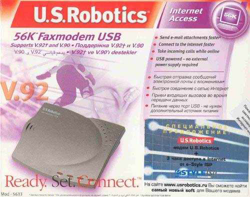
В такой коробке модем поступает в продажу
В комплекте с модемом поставляется USB кабель для подключения к компьютеру, кабель с разъемами RG-11 для подключения к телефонной линии, руководство по установке и настройке и компакт диск с драйверами и документацией.
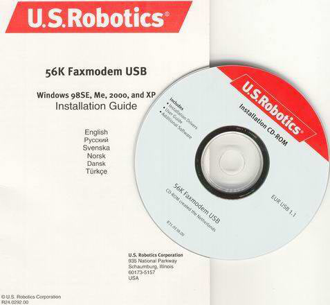
Комплект документации (бумажный вариант и CD)
Дизайн самого устройства также порадовал . Внешне это небольшая серая коробочка с четырьмя индикаторами и названием в левом верхнем углу. Индикаторы, расположенные на модеме, отображают его состояние. Питание/PWR — горит в том случае, если модем подключен к компьютеру и драйверы для него установлены. Подключен/CD — когда модем установил соединение с удаленным модемом и возможна передача данных. Прием данных/RD — мигает при приеме информации и отправке результирующих кодов. Передача данных/SD — сигнализирует при передаче данных с компьютера на модем.
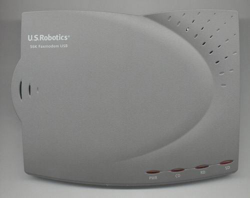
Модем: вид сверху
На нижней стороне корпуса устройства приклеена наклейка с названием модели, серийным номером, отметкой о сертификации в России и некоторой информацией о совместимости и безопасности.
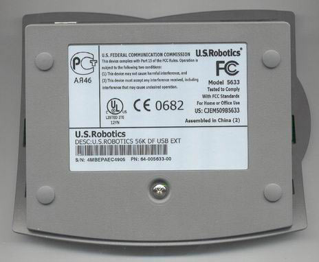
Модем: вид снизу
На задней панели расположены два разъема для телефонной линии и USB разъем для подключения к компьютеру. Заметим, что питание модема осуществляется через USB, и входа для отдельного источника питания нет.
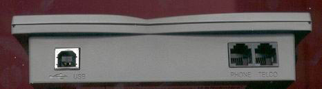
Модем: вид сзади
Мы немного увлеклись этим модемом и решили посмотреть, что же у него внутри. Для этого нам пришлось его разобрать, что не составило особого труда. Как видно, модем выполнен не основе чипа от U.S.Robotics.
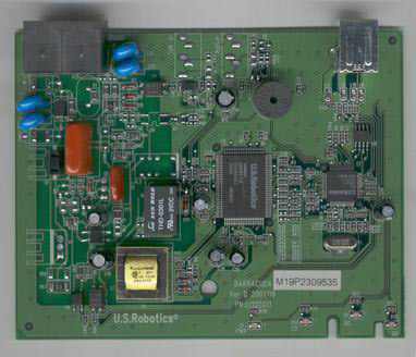
Плата модема
Модем весьма требователен к системе. Минимальные требования его таковы: при использовании ОС Windows 98SE/Me — Pentium II, 300 MГц, 128 МБ ОЗУ, в случае Windows 2000/XP — Pentium III, 500 MГц, 128 МБ ОЗУ.
Возможности
| Возможности модема | |
| Схемы модуляции | V.92, V.90, Технология 56K (получение данных на скорости до 56 Кбит/с и передача с использованием модуляции V.34), V.34 (Включая 33600), V.32 bis, V.32, V.22 bis, V.22, V.23, V.21 |
| Схемы коррекции ошибок и сжатия данных | V.42, V.42 bis, V.44, MNP 2-5 |
| Схемы модуляции факса | V.17, V.29, V.27ter, V.21 |
| Стандарты для факсов | EIA 578 Class 1 FAX |
| Скорости соединения канала (скорости загрузки) | 28000, 29333, 30666, 32000, 33333, 34666, 36000, 37333, 38666, 40000, 41333, 42666, 44000, 45333, 46666, 48000, 49333, 50666, 52000, 53333, 54666 и 56000 |
| Скорости соединения канала (скорости выгрузки) | 4800, 7200, 9600, 12000, 14400, 16800, 19200, 21600, 24000, 26400, 28800 и 31200 |
| Скорости соединения V.34 | 4800, 7200, 9600, 12000, 14400, 16800, 19200, 21600, 24000, 26400, 28800, 31200 и 33600 |
| Скорости соединения V.32 bis | 4800, 7200, 9600, 12000 и 14400 |
| Скорости соединения V.92 | 24000, 25333, 26666, 28000, 29333, 30666, 32000, 33333, 34666, 36000, 37333, 38666, 40000, 41333, 42666, 44000, 45333, 46666, 48000 |
| Дополнительные скорости соединения | 300, 1200/75 (V.23), 1200 и 2400 |
| Скорости факсимильного соединения | 2400, 4800, 7200, 9600, 12000 и 14400 |
Как видите, эта модель, как и полагается современному модему, поддерживает достаточно много протоколов и стандартов передачи данных (схем модуляции), начиная от старого V.21 и заканчивая V.92. Кроме того, есть возможность обновления прошивки. Модем поддерживает загрузку программного обеспечения во встроенную флэш-память.
Немного подробнее следует остановиться на V.92, и его возможностях. Что же такое V.92, и чем он нам интересен? У него есть три новые функции в отличие от V.90. Как помните, стандарт V.90 имел ограничение по скорости передачи 31 200 бит/с, у V.92 максимальная скорость передачи составляет 48 000 бит/с, что достигается за счет технологии «V.PCM-Upstream» (Передача V.PCM).
Второе, чем может похвастаться V.92 — быстрое соединение. Позволяет более быстро устанавливать повторные соединения, предоставляя модему возможность запоминать условия на линии, при поддержке стандарта V.92 с обеих сторон. При первом соединении, модем выполнит полную последовательность согласования и сохранит полученную информацию, которую он будет использовать при следующих попытках соединения. Это позволяет сократить время повторных соединений на 30 — 50%, по данным U.S.Robotics. При невозможности установить оптимальное соединение, будет выполнена полная последовательность согласования.
И, наконец, третье усовершенствование — технология «Modem On Hold» (Удержание модема на связи). Она позволяет удерживать Интернет-соединение при поступлении входящего телефонного вызова. Для этого оператором телефонной связи должна поддерживаться услуга ожидания вызова. После завершения разговора можно вернуться к установленному соединению, не разрывая связь. При установке соединения без поддержки V.92, выдается сообщение, уведомляющее о входящем вызове. Можно ответить на вызов или проигнорировать его. В случае если вы ответите, соединение для передачи данных будет прервано.
Установка и настройка
Как мы и ожидали, серьезных проблем с установкой и настройкой модема, как и других USB устройств, у нас не возникло. Система сразу после подключения устройства определила модем и приступила к поиску драйверов. Мы установили драйверы с компакт диска из комплекта с модемом. Хотя на диске имеются драйверы для Windows XP, система говорит, что они не тестировалась на совместимость с ней.
Установка драйверов
После того, как установка была завершена, на модеме загорелся индикатор PWR/Питание. Заглянув в диспетчер устройств, мы увидели модем — U.S. Robotics 56K Faxmodem USB.
![]()
Модем в диспетчере задач
Программное обеспечение
В комплекте с модемом поставляется специализированное программное обеспечение U.S. Robotics ControlCenter, предназначенное для настройки устройства, подстройки параметров по-умолчанию и обновления прошивки.

Логотип утилиты настройки модема
При каждом запуске, утилита определяет наличие модемов и отображает их в левой части экрана. Щелкнув по изображению модема, можно получить информацию о нем: тип, тактовую частоту, версию прошивки и др.
Характеристики
Согласно данным U.S.Robotics ControlCenter, у нашего модема были следующие характеристики: идентификатор продукта — 5633, тип устройства — USA FCC D/F, тактовая частота — 56 МГц, дата FLASH 31.07.2002, версия FLASH 952.172.061.000.
В левой части окна расположены четыре кнопки. Первая — диспетчер конфигурации, в котором можно настроить многие функции устройства. Вторая -открывает окно терминала, в котором можно ввести AT-команды для устройства, а также выполнить передачу и прием файлов. Третья — открывает окно Флэш с диска. Четвертая — открывает окно быстрого обновления, в котором можно загрузить и обновить программное обеспечение продукта.
Диспетчер конфигурации содержит пять вкладок. Подстройка скорости может использоваться для настройки соотношения исходящего и входящего потока данных, передаваемых и получаемых модемом. Если необходимо передавать данные, можно оптимизировать передачу путем установки скорости отправки 48K, которая увеличит исходящий поток за счет уменьшения входящего потока. Существует скоростной диапазон от 28K до 56K для получения, и от 24K до 48K для передачи.
Вкладка ICN позволяет установить параметры для уведомления о вызове через Internet (ICN). С помощью этой функции можно принимать поступающие телефонные вызовы, для чего активное модемное соединение временно переводится в состояние ожидания. После ответа на голосовой вызов (телефонный звонок) и его завершения можно продолжить сеанс соединения. Требует V.92.
Контроль вызовов
На вкладке «Контроль вызовов» можно изменить восемь параметров для вызовов. Эти параметры определяют типы соединений, которые это устройство может устанавливать с удаленным устройством. Настройки можно изменять с помощью команд, которые посылаются системным программным обеспечением, при выполнении вызова. В параметре Количество звонков до ответа устанавливается необходимое число звонков, выполненных устройством до ответа на входящий вызов. В поле Время ожидания задается промежуток времени, в течение которого устройство будет ожидать соединения с сигналом во время набора номера удаленного узла. Вы также можете ограничить скорость, с которой будет устанавливаться соединение. Можно ограничить как сверху, так и снизу. Сжатие данных позволяет устройству сжимать данные и передавать их по каналам с низкой скоростью соединения. Коррекция ошибок используется для определения и исправления ошибок во время передачи данных, не прерывая сеанса связи. Параметры Отключить модуляции позволяют отключить один или несколько протоколов связи. Используется в основном для поиска и устранения неисправностей. Еще одна группа параметров, которые используются в основном для диагностики — Отключить символьные скорости протокола V.34 позволяют отключить одну или несколько символьных скоростей протокола V.34.
Интерфейс устройства DTE
Следующая вкладка — интерфейс устройства DTE. Здесь можно изменять девять параметров, которые настраивают устройство для обработки сигналов, поступающих на компьютер и от него, а также определяют способ отображения результирующих кодов. Сигнал DTR передается от компьютера на модем и сообщает о готовности компьютера. Компьютер передает этот сигнал только после получения соответствующих инструкций, например, когда запущено коммуникационное программное обеспечение. Если модем прекращает получать сигнал DTR, то он воспринимает это как разрыв соединения с компьютером и сразу вешает трубку. Сигнал DCD передается с модема на компьютер, для сообщения об успешной установке соединения с другим модемом. Это поле используется для настройки обработки сигналов DCD устройством. Сигнал готовности к работе DSR сообщает устройству DTE о том, что модем существует. Модем передает этот сигнал, когда он включен. Группа Результирующие коды позволяет настроить обработку результирующих кодов устройством. Отображаемые результирующие коды, определяет результирующие коды, которые посылаются устройством при наборе. Дополнительные результирующие коды, определяет, будет ли устройство посылать дополнительные результирующие коды после соединения. Эхо используется только для специальных операций по поиску и устранению неисправностей. Управление потоком (TX/RX) определяет тип управления потоком передаваемых и принимаемых данных. Скорость устройства DTE определяет скорость потока данных, которую ожидает устройство связи.
На вкладке Сброс можно выбрать шаблон, который будет использован для восстановления стандартных настроек для устройства. При этом сбрасываются значения всех полей на всех вкладках программы ControlCenter.
Здесь также есть кнопка с названием Терминал. Не трудно догадаться, что она используется для запуска терминала, в котором можно ввести AT-команды для устройства, также выполнить передачу и прием файлов.
Следующее, что здесь есть — это Флэш с диска. Позволяет установить последнюю версию прошивки U.S.Robotics для данного устройства из файла *.dmf, который ранее был загружен по сети и сохранен на 3.5-дюймовой дискете или жестком диске.
И последнее, что стоит здесь рассмотреть — Быстрое обновление. Позволяет проверить, является ли установленная на Вашем устройстве версия программного обеспечения U.S.Robotics самой последней из существующих версий. Если нет, то ControlCenter загрузит последнюю версию программного обеспечения автоматически. На вкладке Общий можно выбрать один или несколько продуктов, которые нужно обновить. На вкладке Планирование можно указать периодичность с которой вы планирует проводить обновления. Вкладка Подключение позволяет регистрировать все события во время любого сеанса активного соединения. На вкладке Общие задаются общие параметры для утилиты «быстрое обновление». И последняя вкладка — Соединение, на ней можно задать параметры Интернет-соединения для всех устройств, поддерживаемых программой ControlCenter.
Тестирование
Мы провели две серии тестов, одну для аналоговой линии и одну для цифровой. В обоих случаях тестирование проводилось на машинах под управлением ОС Windows XP Professional. Мы предумышленно не делали ничего, что могло улучшить, либо ухудшить скорость работы модема. Установив драйвер и указав данные подключения, мы перешли непосредственно к тестированию. Во всех тестах скачивался файл размером 3,5 Мб с сервера провайдера.
Первая группа тестов
Начнем с тестирования модема на цифровой линии:
Как мы и ожидали, проблем с подключением у нас не возникло. Модем сразу установил соединение, при этом скорость составила 46,7 кбит/с. На скачивание файла у нас ушло 12 минут 44 секунды. Средняя скорость загрузки составила 4580 cps.
После этого мы разорвали соединение и установили его заново. Скорость оказалась такой же — 46,7 кбит/с. При следующем скачивании результат оказался немного лучше — 12 минут 15 секунд. Скорость загрузки — 4760 cps.
И результат третьего скачивания был 12 минут 35 секунд. Скорость соединения оказалась той же — 46,7 кбит/с. Скорость загрузки — 4630 cps
| Размер файла, Мб | Скорость соединения, кбит/с |
Скорость загрузки, cps |
Время загрузки, м,с. |
| 3,5 | 46,7 | 4580 | 12,44 |
| 3,5 | 46,7 | 4760 | 12,15 |
| 3,5 | 46,7 | 4630 | 12,35 |
Вторая группа тестов
Следующим этапом было тестирование на аналоговой линии. Как мы и ожидали, здесь результаты оказались заметно хуже. Хотя мы были готовы встретить проблемы при подключении, мы их не встретили. Мы выполнили три тестовых подключения и для каждого из них выполнили загрузку 3,5 мегабайтного файла.
При первом подключении, как и при втором и третьем, скорость соединения составила 33,2 кбит/с. На первую загрузку у нас ушло 17 минут 34 секунды. Скорость загрузки составила 3320 cps.
При второй загрузке скорость оказалась существенно выше и составила 3680 cps, при этом время уменьшилось до 15 минут 51 секунды.
На третьей итерации мы не увидели ничего интересного, скорость составила 3580 cps, время загрузки — 16 минут 17 секунд.
| Размер файла, Мб | Скорость соединения, кбит/с | Скорость загрузки, cps |
Время загрузки, м,с. |
| 3,5 | 33,2 | 3320 | 17,34 |
| 3,5 | 33,2 | 3680 | 15,51 |
| 3,5 | 33,2 | 3580 | 16,17 |
Попытаемся подвести итог результатам тестирования. При использовании этого модема на цифровых линиях, он показывает скорость на 24 — 43 % больше, чем на аналоговых. Среднее значение cps на цифровой линии составило 4660, на аналоговой — 3530. Разница между средними значениями составила 1130, или 32 %.
Среднее время загрузки на цифровой линии составило 12 минут 31 секунда, на аналоговой — 16 минут 34 секунды.
В обоих случаях скорость соединения была стабильна. Для цифровой линии составила 46,7 кбит/с, для аналоговой — 33,2 кбит/с. Такая стабильность не могла не порадовать.
Выводы
После того, как тестирование завершено, можно сделать некоторые выводы. Начнем с того, что нам понравилось в этом модеме. Конечно, нельзя не сказать о дизайне этого устройства. Небольшая красивая темно-серая коробочка с четырьмя индикаторами. Нам понравилось, что для этого модема не надо подключать внешний источник питания, используется питание от USB. Кроме того, скорость работы модема оказалась достаточно хорошей на цифровой линии. На аналоговой линии скорость, хотя и была заметно ниже, она не вызывала особых проблем. При тестировании модем хорошо держал линию, мы заметили только одно произвольное, как нам показалось сначала, отключение, чуть позже оказалось, что на счете кончились деньги. Таким образом, мы не заметили ни одного отключения модема от линии по его вине.
Из минусов стоит отметить, что скорость при работе на аналоговой линии могла быть и больше.
При тех результатах, которые мы получили, можно порекомендовать этот модем тем, кто собирается его использовать на цифровых АТС, но это вовсе не означает, что его нельзя использовать на аналоговых АТС.
Если Вы заметили ошибку — выделите ее мышью и нажмите CTRL+ENTER.
-
9, 99 99 9 Regulatory Information CE Compliance We, U.S. Robotics Corporation of 935 National Parkway, Schaumburg, Illinois, 60173-5157 USA, declare under our sole responsibility that the product, U.S. Robotics 56K Faxmodem, Model 5630, to which this declaration relates, is in conformity with the following standards and/or other normative documents. EN60950 EN55022 EN55024 EN61000-3-2 EN61000-3-3 …
-
22, 2222 2222 22 5.3 DANS LA MESURE OU LA LOI LE PERMET, LES GARANTIES ET LES RECOURS PRECEDEMMENT CITES SONT EXCLUSIFS ET REMPLACENT LES AUTRES GARANTIES, TERMES OU CONDITIONS, EXPLICITES OU IMPLICITES, DE FACTO OU DE JURE, STATUTAIRES OU AUTRES, NOTAMMENT LES GARANTIES, TERMES OU CONDITIONS DE COMMERCIALISATION, D’ADAPTATION A UN USAGE PARTICULIER, DE QUALITE SATISFAISANTE, DE …
-
6, 66 66 6 If you have Windows 2000: Step 5: Update the driver from the Installation CD-ROM Click Windows Start, Settings, and Control Panel. Double-click System, click the Hardware tab, and click the Device Manager button. Click to expand Modems, and double-click Standard Modem. Click the Driver tab and click the Update Driver button. When the Upgrade Device Driver window appears, cli…
-
11, 1111 1111 11 4.04.0 4.04.0 4.0 WARRANTY REPLACEMENT:WARRANTY REPLACEMENT: WARRANTY REPLACEMENT:WARRANTY REPLACEMENT: WARRANTY REPLACEMENT: 4.1 In the event U.S. ROBOTICS Technical Support or its authorised U.S. ROBOTICS Service Centre determines the product or part has a malfunction or failure attributable directly to faulty workmanship and/or materials; and the product is within the TWO (2) …
-
39, 3939 3939 39 Paese Telefono E-mail Orario Italia 848 809 903 [email protected] 9:00 — 18:00, lunedì — venerdì Regno Unito +44 870 844 4546 [email protected] 9:00 — 17:30, lunedì — venerdì Informazioni di conformità Conformità CE U.S. Robotics Corporation (935 National Parkway, Schaumburg, Illinois, 60173-5157, USA) dichiara, sotto la propria responsabilità, che U.S. Robot…
-
37, 3737 3737 37 Windows 2000/XP: fare clic su Start, ImpostazioniStart, Impostazioni Start, ImpostazioniStart, Impostazioni Start, Impostazioni (se applicabile), quindi su PP PP P annello di controlloannello di controllo annello di controlloannello di controllo annello di controllo. Fare doppio clic sull’icona Opzioni modem e telefonoOpzioni modem e telefono Opzioni modem e…
-
16, 1616 1616 16 vous saurez quel port COM est attribué à votre modem. Cliquez sur FermerFermer FermerFermer Fermer. Lorsque la fenêtre « Modification des paramètres système » apparaît à l’écran, cliquez sur OuiOui OuiOui Oui pour redémarrer votre ordinateur. Si vous disposez de Windows 2000 : Etape 5 : mise à jour du pilote à partir du CD-ROM d’installation. Cl…
-
28, 2828 2828 28 PRPR PRPR PR OBOB OBOB OB LL LL L EE EE E M: Mein Modem scheint mit einem anderM: Mein Modem scheint mit einem ander M: Mein Modem scheint mit einem anderM: Mein Modem scheint mit einem ander M: Mein Modem scheint mit einem ander en Modem en Modem en Modem en Modem en Modem VV VV V erbindungerbindung erbindungerbindung erbindung aufzunehmen, aber ohne Erfolg.auf…
-
4, 44 44 4 EnglishEnglish EnglishEnglish English U.S. Robotics Corporation 935 National Parkway Schaumburg, Illinois 60173 No part of this documentation may be reproduced in any form or by any means or used to make any derivative work (such as translation, transformation, or adaptation) without writ- ten permission from U.S. Robotics Corporation. U.S. Robotics Co…
-
5, 55 55 5 All Windows Operating Systems Installation Step1: Prepare for installation NONO NONO NO TT TT T EE EE E: Before you begin, we recommend you uninstall any other modems you have in your system. Refer to your previous modem’s documentation for instructions. Write down your new U.S. Robotics modem’s serial number, which is located on the white bar code sticker…
-
40, 4040 4040 40 Garanzia limitata di U.S. Robotics Corporation 1.01.0 1.01.0 1.0 CC CC C ONON ONON ON DIZDIZ DIZDIZ DIZ IONION IONION ION I GI G I GI G I G EE EE E NN NN N EE EE E RARA RARA RA LILI LILI LI 1.1 La presente garanzia limitata è concessa esclusivamente all’utente/acquirente originale (CLIENTE) e non è trasferibile. 1.2 Nessun agente, rivenditore o partner commerciale…
-
15, 1515 1515 15 Pour tous les systèmes d’exploitation Windows Etape 1 : préparation de l’installation. RR RR R EE EE E MM MM M AA AA A RR RR R QUE QUE QUE QUE QUE : avant de procéder à l’installation, nous vous conseillons de désinstaller tout autre modem faisant partie de votre système. Reportez-vous au manuel de votre ancien modem pour connaître les instructions de désinst…
-
20, 2020 2020 20 Garantie limitée de U.S. Robotics Corporation 1.01.0 1.01.0 1.0 CONDITIONS GENERALES :CONDITIONS GENERALES : CONDITIONS GENERALES :CONDITIONS GENERALES : CONDITIONS GENERALES : 1.1 Cette garantie limitée ne s’applique qu’à l’acheteur d’origine (le CLIENT) et n’est pas transférable. 1.2 Aucun agent, revendeur ou partenaire commercial …
-
38, 3838 3838 38 PROBLEMA: il modem non raggiunge una connessione Internet a 56K.PROBLEMA: il modem non raggiunge una connessione Internet a 56K. PROBLEMA: il modem non raggiunge una connessione Internet a 56K.PROBLEMA: il modem non raggiunge una connessione Internet a 56K. PROBLEMA: il modem non raggiunge una connessione Internet a 56K. Il protocollo V.90/V.92 consente velocità di download f…
-
7, 77 77 7 success. If your modem is not listed and/or you do not see a series of commands and responses, check that all connectors and power cables are properly connected to your modem and the back of your computer. Check that the modem is switched on and the CS or the PWR light is illuminated. Shut down and restart your PC. Check your modem again using the Control…