5 причин купить противокражные ворота

Подходят ко всем объектам коммерческого типа

Собственная лаборатория и только мировые стандарты

Световая и звуковая индикация режимов тревоги

Максимальное количество встроенных функций

Применение радиочастотных и акустомагнитных технологий
За долгие годы работы в сфере продажи противокражных ворот, компания “AMlogo” накопила большой опыт взаимодействия с различными владельцами бизнеса в сфере торговли, оборудовав десятки тысяч рабочих мест
По вопросам приобретения
![]()
Просто оставьте заявку,
наш менеджер свяжется с Вами
и
ответит
на все интересующие вопросы:
ДЕСЯТКИ МИЛЛИОНОВ РУБЛЕЙ СЭКОНОМЛЕНЫ С ПОМОЩЬЮ
ПРОТИВОКРАЖНЫХ ВОРОТ
В России существует не 2 проблемы, о которых все и так знают, а именно 3. И третья проблема для любого бизнеса это воровство: кассиров, в зоне приёмки товаров, персонала и, конечно же, покупателей. Больший процент воровства приходится именно на покупателей в любой торговой точки, особенно если в ней ежедневый большой “конвейер” трафика.

В зону риска попадают практически все категории товаров, но больший процент, остаётся за так называемыми штучными и небольшими товарами, которые легко “забыть” в сумочке или кармане. Но уже сегодня ситуация стала меняться в положительную сторону, благодаря новым технологиям применяемым в повседневной жизни и благодаря этому способствовало развитие специализированной системе, которая называется инструкция anti theft system.
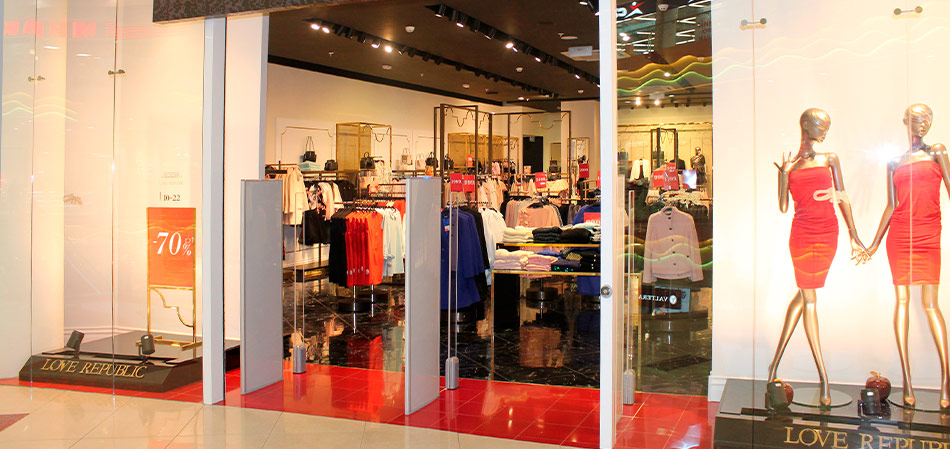

Если ранее приходилось справляться своими силами, в числе которых была охрана и видеонаблюдение, то уже сегодня воровство стало массовым не только в небольших торговых точках, но и в крупных гипермаркетах. Как показывает статистика, на воровстве зачастую попадаются не только дети и пенсионеры, но и люди со средним и даже высоким достатком, поэтому нельзя отнести воровство товаров к одной определённой категории.

Только вдумайтесь в цифры: за последние несколько лет подсчитано, что урон от краж покупателей в средней по проходимости торговой точке может достигать до 10%-15% от общего оборота товаров в год, а при применении этого специального оборудования урон был снижен до 1%-3% так же от общего оборота товаров. Благодаря этим специализированным воротам известны случаи, когда бизнес благодаря сокращению потерь от краж, мог за несколько месяцев расшириться с одной торговой точки, до нескольких. Не это ли самый главный показатель эффективной и профессиональной защиты товара и бизнеса в целом.
выберите противокражные ворота
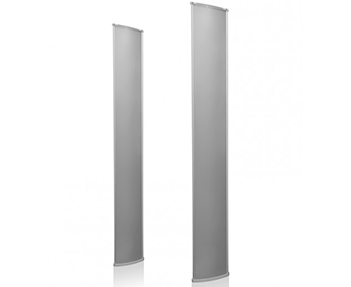
Акустомагнитные противокражные ворота
Ultra Shield
Благодаря счетчику количества посетителей, считывает поток покупателей.
Акустомагнитные противокражные ворота
Alarma Air
Лёгкая настройка и уникальный дизайн, все эти черты делают систему популярной.
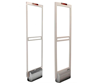
Радиочастотные противокражные ворота
UT-303
Очевидные плюсы системы, за счёт высоких характеристик детекции.
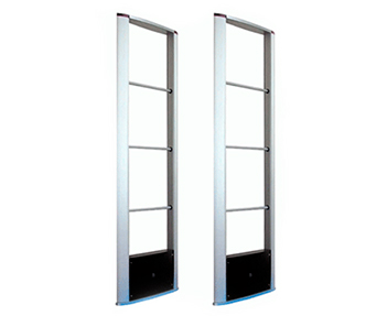
Противокражные радиочастотные ворота
Gateway Spectra
Стильный дизайн, простота использования и работа со всеми датчиками и этикетками.
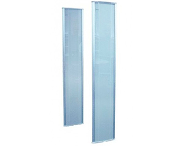
Акустомагнитные противокражные ворота
Ulra Exit 2.0
Устанавливают в широких проходах магазинов, за счёт большого покрытия.
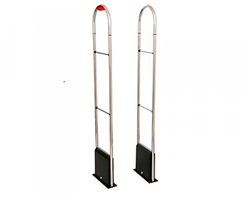
Радиочастотные противокражные ворота
Lucatron Venus VNS-200
Часто эта система используется не только в магазинах, но и бутиках.
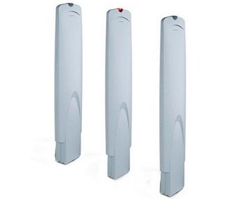
Акустомагнитные противокражные ворота
Ultra Post IV
В корпус встроен специализированный датчик для обнаружения помех.
Акустомагнитные противокражные ворота
Alarma Steel
Готовое решение работающее в том числе и металлизированными товарами.
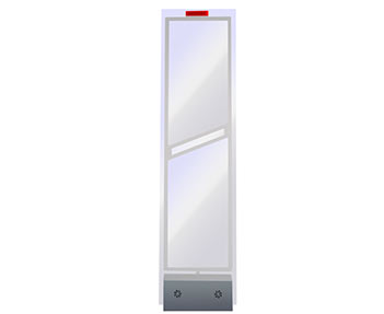
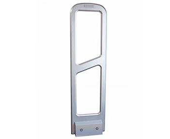
Противокражные ворота
Detex Line Start
Антенны представлены в виде узких стоек, позволяющие экономить место.
Загрузка…
 Loading…
![]()
Do not discard!
This document may be required by code inspectors. Leave it at the site until the installation is complete and the system has been approved.
Ultra 1.5 meter ABS Pedestal System®
Installation Guide
ZS1146-P, ZS1146-S, ZA1146-D
© 2018 Sensormatic Electronics, LLC
ULTRA 1.5 METER ABS PEDESTAL SYSTEM INSTALLATION GUIDE
|
8200-1048-06, REV. A |
|
|
1 of 44 |
*8200-1048-06* |

Contents |
|
|
About this guide …………………………………………………………………………………………………………………………….. |
3 |
|
About the Ultra 1.5 meter ABS Pedestal System ……………………………………………………………………………… |
3 |
|
Kit parts ……………………………………………………………………………………………………………………………………… |
4 |
|
Supported configurations ……………………………………………………………………………………………………………… |
5 |
|
Coverage distances …………………………………………………………………………………………………………………….. |
5 |
|
Compatibility……………………………………………………………………………………………………………………………….. |
5 |
|
Safety ………………………………………………………………………………………………………………………………………… |
6 |
|
Installation overview ………………………………………………………………………………………………………………………. |
8 |
|
Section I: Before you begin…………………………………………………………………………………………………………….. |
9 |
|
Planning the location of system components…………………………………………………………………………………… |
9 |
|
Installation requirements …………………………………………………………………………………………………………….. |
10 |
|
System requirements …………………………………………………………………………………………………………………. |
11 |
|
Section II: Installation …………………………………………………………………………………………………………………… |
12 |
|
Overview of installation steps………………………………………………………………………………………………………. |
12 |
|
Step 1: Removing the pedestal covers …………………………………………………………………………………………. |
12 |
|
Step 2: Positioning the pedestals…………………………………………………………………………………………………. |
12 |
|
Step 3: Routing the cables ………………………………………………………………………………………………………….. |
13 |
|
Step 4: Securing the pedestal to the floor……………………………………………………………………………………… |
14 |
|
Section III: Connecting the Ultra 1.5m ABS Pedestal……………………………………………………………………… |
15 |
|
Overview of connection steps ……………………………………………………………………………………………………… |
15 |
|
Step 1: Connecting the primary pedestal………………………………………………………………………………………. |
15 |
|
Step 2: Connecting the secondary pedestal ………………………………………………………………………………….. |
17 |
|
Step 3: Connecting AC power……………………………………………………………………………………………………… |
18 |
|
Step 4: Tuning the Ultra 1.5 meter ABS Pedestal System ………………………………………………………………. |
22 |
|
Step 5: Checking EAS performance …………………………………………………………………………………………….. |
28 |
|
Step 6: Adjusting the audio alarm ………………………………………………………………………………………………… |
28 |
|
Step 7: Installing the pedestal covers …………………………………………………………………………………………… |
28 |
|
Step 8: Covering the antenna cables……………………………………………………………………………………………. |
29 |
|
Step 9: Applying anti-theft labels in other languages………………………………………………………………………. |
29 |
|
Step 10: Cleaning the pedestal……………………………………………………………………………………………………. |
29 |
|
Field replaceable units………………………………………………………………………………………………………………….. |
30 |
|
Boot Loader Mode………………………………………………………………………………………………………………………… |
30 |
|
Specifications ………………………………………………………………………………………………………………………………. |
32 |
|
Declarations…………………………………………………………………………………………………………………………………. |
33 |
|
Appendix A: Dimensions………………………………………………………………………………………………………………. |
34 |
|
Appendix B: Connecting an Auxiliary Receiver……………………………………………………………………………… |
35 |
|
Appendix C: Connecting an UltraLink …………………………………………………………………………………………… |
36 |
|
Appendix D: Connecting a Local Device Manager …………………………………………………………………………. |
39 |
|
Appendix E: Connecting a Digital Remote Alarm…………………………………………………………………………… |
41 |
|
Appendix F: Main board pinouts …………………………………………………………………………………………………… |
44 |
ULTRA 1.5 METER ABS PEDESTAL SYSTEM INSTALLATION GUIDE
|
8200-1048-06, REV. A |
|
|
2 of 44 |
*8200-1048-06* |

About this guide
This installation guide explains how to install the Ultra 1.5 meter ABS Pedestal System. You must install the Ultra 1.5 meter ABS Pedestal System as outlined in this guide. Other related documents that can help you with this installation, include the following:
•CBC-4055 Local Device Manager Installation Guide, 8200-0858-01
•CBC-4020 UltraLink Indoor Installation and Service Guide, 8200-0172-01
•AMC-1060 Digital Remote Alarm Installation Guide, 8200-0505-01
Customer requirements dictate the placement of system components. Your Sensormatic representative supplies this information separately.
Regulatory restriction: For indoor use only.
Intended use: Only install this device as described in this guide.
If this product was installed in a European Union or European Free Trade Association member state, give the Declaration of Conformity included with this product to the manager or user. By law, you must provide this information to the user.
Technical support
For product bulletins, and the most recent updates to this document, visit https://sensormaticsecurelogin.com.
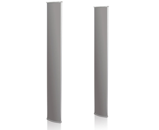
About the Ultra 1.5 meter ABS Pedestal System
The Ultra 1.5 meter ABS Pedestal System described in this document activates an alarm when it detects the unique response of an active Ultra•Max® hard tag or disposable label.
The Ultra 1.5 meter ABS Pedestal System consists of two pedestal antennas, a primary and a secondary, connected by an interconnect cable. The primary pedestal connects to a power source and has an alarm board and the main controller board. The secondary pedestal does not have a LED alarm indicator; it has the lens cover and contains a receiver board.
Product features
The Ultra 1.5 meter ABS Pedestal System is similar to the Ultra•Shield systems, but the system has the following additional features:
•An aesthetic look that meets and exceeds competitive offerings.
•Supports single and dual configurations.
•Integrated audio and visual alarming in the primary pedestal.
•Jammer detection.
•Tags-too-close.
•Network connectivity through the use of a Local Device Manager (LDM).
•The system has a single door coverage capability of 0.9 meters or 3 feet, and a double door coverage capability of 1.5 meters, or 5 feet.
ULTRA 1.5 METER ABS PEDESTAL SYSTEM INSTALLATION GUIDE
|
8200-1048-06, REV. A |
|
|
3 of 44 |
*8200-1048-06* |

Kit parts
This section outlines the components you require to install the Ultra 1.5 meter ABS Pedestal System.
Ultra 1.5 meter ABS Pedestal System
Table 1 lists the kit parts you require to install the Ultra 1.5m ABS Single Pedestal System, ZS1146-P. Table 2 lists the kit parts you require to install the Ultra 1.5m ABS Secondary Pedestal System, ZS1146-S. Table 3 lists the kit parts you require to mount the Ultra 1.5 meter ABS Pedestal System.
Table 1. Ultra 1.5m ABS Single Pedestal System, ZS1146-P
|
Kit |
Product code |
Quantity required |
|
Primary pedestal assembly with cover |
0304-3039-01 |
1 |
|
Pedestal mounting installation kit |
0352-0781-01 |
1 |
|
Table 2. Ultra 1.5m ABS Secondary Pedestal System, ZS1146-S |
||
|
Kit |
Product code |
Quantity required |
|
Secondary pedestal assembly with cover |
0304-3040-01 |
1 |
|
Pedestal mounting installation kit |
0352-0781-01 |
1 |
Table 3. Pedestal Mounting Installation Kit, 0352-0781-01
|
Part |
Part number |
Quantity required |
|
Washer flat |
2848-0025-01 |
4 |
|
Anchors expansion, 5/16” x 1-3/4” |
2880-0105-01 |
4 |
|
Bolt, lag, 5/16“ x 2.5“, 1/2″ Hex |
2880-0106-01 |
4 |
|
Screws, Hex, M6 x 60 |
5801-4174-520 |
2 |
|
Washer, flat, M8 |
5840-0700-020 |
2 |
Interconnect cable options for the Ultra 1.5 meter ABS Pedestal System
Interconnect cables connect the primary and the secondary pedestal.
Table 4 lists the kit parts you require to install the 4 meter interconnect cable.
Table 5 lists the kit parts you require to install the 12 meter interconnect cable.
Table 6 lists the kit parts you require to install the 15 meter interconnect cable.
Table 4. AMS-1146 4M TX Interconnect Cable Installation Kit, 0352-0792-01
|
Item |
Part number |
Quantity required |
|
Cable Assembly, transceiver |
0652-0789-01 |
1 |
Table 5. AMS-1146 12M TX Interconnect Cable Installation Kit, 0352-0793-01
|
Item |
Part number |
Quantity required |
|
Cable Assembly, transceiver |
0652-0789-02 |
1 |
Table 6. AMS-1146 15M TX Interconnect Cable Installation Kit, 0352-0794-01
|
Item |
Part number |
Quantity |
|
Cable Assembly, transceiver |
0652-0789-03 |
1 |
ULTRA 1.5 METER ABS PEDESTAL SYSTEM INSTALLATION GUIDE
|
8200-1048-06, REV. A |
|
|
4 of 44 |
*8200-1048-06* |

Supported configurations
The Ultra 1.5 meter ABS Pedestal System supports single and dual configurations.
Coverage distances
Table 7 lists the exit coverage capabilities of the Ultra 1.5 meter ABS Pedestal System.
Table 7. Ultra 1.5 meter ABS Pedestal System exit coverage capabilities
|
Ultra 1.5 meter ABS Pedestal System configuration |
Exit coverage distance |
|
Single |
0.9 meters, or 3 feet |
|
Dual alternating |
1.5 meters, or 5 feet |
Compatibility
The Ultra 1.5 meter ABS Pedestal System is compatible with the following products:
•Ranger Antennas
•Satellite Antennas
•Amorphous Core Receiver
Note: Compatible with one Amorphous Core Receiver only, not a pair of receivers.
•Digital Remote Alarm (DRA)
•Ultra Link
•Local Device Manager (LDM)
•Wireless Device Manager (BIM1000) and the Wireless Device Module (BIX1000)
ULTRA 1.5 METER ABS PEDESTAL SYSTEM INSTALLATION GUIDE
|
8200-1048-06, REV. A |
|
|
5 of 44 |
*8200-1048-06* |

Safety
Installation requirements
 Intended use: Only install this device as described in this guide.
The installer or contractor must adhere to the following criteria:
•Have electrical work comply with the latest national electrical code, national fire code, and all applicable local codes and ordinances. National or local wiring codes or rules can differ between regions. Adherence to these codes supersedes instructions in this document.
•Coordinate all work with other trades to avoid interference.
•Verify existing site conditions and coordinate with the owner’s representative and appropriate utilities as required.
•Obtain copies of all related plans, specifications, shop drawings and addenda to schedule and coordinate related work.
•Thoroughly review the project to ensure that all work meets or exceeds the above requirements. The installer or contractor must bring any alleged discrepancies to the attention of Sensormatic Electronics.
Chemical interaction
WARNING: Do not install this product in hazardous areas where highly combustible or explosive products are stored or used.
Cabling
WARNING: Risk of electric shock
During installation, if the antenna must be left unattended, turn off power or cover high voltage components to prevent unauthorized access to hazardous voltages.
WARNING: Risk of electric shock
The AC power could be carrying 120Vac or 240Vac.
WARNING: Risk of electric shock
The transmit pedestal contains hazardous voltages. If the pedestal must be left unattended with its high voltage components exposed, turn off power or cover these components to avoid unauthorized persons access to hazardous voltages.
WARNING: Do not run the power and comm cables in the same conduit or raceway. Building codes require that power wiring be separated from other types of wiring.
WARNING: In accordance with the USA National Electric Code and applicable US local codes, a 15A or 20A, 2 pole, ganged disconnect device, which also provides short circuit and overload protection and has a minimum 3 millimeter open circuit clearance, must be installed by a licensed electrician at a location readily accessible to the equipment.
For installations in other countries, an electrical outlet, suitable for the voltage and current used in the primary electrical supply input of the equipment, must be already provided or installed by a qualified electrician. The National Electric Codes, regulations, cable, and fusing requirements applicable for the equipment and type of installation must be followed at all times.
ULTRA 1.5 METER ABS PEDESTAL SYSTEM INSTALLATION GUIDE
|
8200-1048-06, REV. A |
|
|
6 of 44 |
*8200-1048-06* |

CAUTION: The AC source must be a two-wire plus ground, 24-hour, unswitched outlet with less than 0.5Vac between neutral and ground.
CAUTION: For permanently connected equipment, a 15A or 20A, two-pole, ganged disconnect device, which also provides short circuit and overload protection, and has a minimum 3 millimeter open circuit clearance, in accordance with the National Electric Code and applicable local codes must be installed by a licensed electrician at a location readily accessible to the equipment.
CAUTION: For pluggable equipment, the socket-outlet shall be installed near the equipment and shall be easily accessible.
Important:
•Do not share the AC source with neon signs, motors, computers, cash registers, terminals, or data communications equipment.
•Do not use orange-colored outlets dedicated for computer equipment.
CAUTION: For continued protection against risk of fire, replace fuse only with same type and rating.
Implanted medical devices
This anti-theft system complies with all applicable safety standards. However, people with implanted electronic medical devices can ask if the store has an anti-theft system, and its location. Although most anti-theft systems are easily seen, some can be concealed. To help individuals with implanted medical devices, consider the following health and safety guidelines:
Health and safety
Place the anti-theft system antennas to ensure customers behave in the following ways:
• Do not linger near, or lean on them while making their purchase.
•Are only near the front of them while exiting the checkout area. For exit systems, place anti-theft system antennas:
•Close to exit and entrance doors, encouraging the customer to pass through them. Do not use antennas intended for exits in an aisle configuration.
•Away from fixtures, equipment, amusements, and other signage that can attract customers to them.
Apply ‘Anti-theft’ signage
•‘Anti-theft’ labels are placed on each antenna, including those hidden behind door frames and other structures. Do not cover these labels with other signage.
•In non-English speaking countries, apply ‘Anti-theft’ labels in the local language to the antennas. For hidden antennas, apply an ‘Anti-theft’ label in the local language to each side of the door frame facing the doorway about 1.2 meters or 4 feet above the floor. You can order local language labels, 2412-0170-XX, from your distribution center.
•To improve customer awareness of the anti-theft system, encourage the store to display signs that state it has an anti-theft system. You can order awareness materials through your sales representative.
ULTRA 1.5 METER ABS PEDESTAL SYSTEM INSTALLATION GUIDE
|
8200-1048-06, REV. A |
|
|
7 of 44 |
*8200-1048-06* |

Installation overview
Figure 1 gives an overview of the installation sequence you must follow when installing the Ultra 1.5 meter ABS Pedestal System.
Figure 1. Ultra 1.5 meter ABS Pedestal System installation overview
Section I:
Before you begin
Complete all the prerequisites in Section I before you install the Ultra 1.5 meter ABS Pedestal System.
|
Section II: |
Section III: |
|
Installation |
Connecting the system |
|
Install the system |
Connect the Ultra 1.5 |
|
components for the |
meter ABS Pedestal |
|
Ultra 1.5 meter ABS |
System components, |
|
Pedestal System. |
and verify that they |
|
work. |
ULTRA 1.5 METER ABS PEDESTAL SYSTEM INSTALLATION GUIDE
|
8200-1048-06, REV. A |
|
|
8 of 44 |
*8200-1048-06* |

Section I: Before you begin
This section outlines the criteria you must adhere to when you install the Ultra 1.5 meter ABS Pedestal System.
Training
Do not attempt to install the Ultra 1.5 meter ABS Pedestal System unless you have completed the Ultra 1.5 meter ABS Pedestal System Training webinar. To schedule a webinar or in class training, contact your regional training representatives.
Planning the location of system components
This section outlines how to determine the location for the components of the Ultra 1.5 meter ABS Pedestal System.
Pedestal location
Consider the following criteria when you select the location of the Ultra 1.5 meter ABS Pedestal System:
•Whenever possible, keep the antennas at least 2.4 meters, or 8 feet away from noise sources such as computer monitors, TVs, switching power supplies, and neon displays.
•Maximum exit coverage of one primary pedestal is 0.9 meters, or 3 feet.
•The pedestals can protect a space 1.5 meters, or 5 feet wide between them, the primary pedestal also detects 90 centimeters, or 3 feet behind for total exit coverage of 2.4 meters, or 8 feet.
•The maximum distance between the primary and the secondary pedestals is 1.5 meters or 5 feet, measured from pedestal center to pedestal center. The minimum distance between two pedestals is
0.6 meters or 2 feet, measured center to center.
•If you must route the interconnect cable over the top of the doors, the maximum cable distance between the pedestals is either 15 meters, or 50 feet, or 12 meters, or 40 feet, depending on which cable option the pedestal has. You usually route the supplied 4 meter or 13 feet cable in the floor.
•A transmit field is emitted from both sides of the primary pedestal. Unless you are using backfield reduction configuration, keep displays that are tagged at least 1.5 meters or 5 feet, from the pedestal, especially when using the tag-too-close function.
•You mount the pedestal to the floor using the four anchors in the AMS-1146 Pedestal Mounting Installation Kit, 0352-0781-01.
•Cable openings in the pedestal base allow for cable entry from underneath the pedestal or from either end of the pedestal through a cutaway in the base covers.
•Cable access can be through conduit or Wiremold®.
AMC-1060 Digital Remote Alarm
If you are using an AMC-1060 Digital Remote Alarm with the Ultra 1.5 meter ABS Pedestal System, consider the following criteria:
•The Ultra 1.5 meter ABS Pedestal System does not provide power for the AMC-1060 Digital Remote Alarm, because the system does not provide power, you need a nearby power outlet. If installing an AMC-1060, confirm the location of the power outlet before you run the wires.
•Plug the 12V DC transformer used to power the alarm, into a 24-hour unswitched outlet.
•The maximum cable distance from the primary pedestal to each remote alarm is about 12.2 meters, or 40 feet.
ULTRA 1.5 METER ABS PEDESTAL SYSTEM INSTALLATION GUIDE
|
8200-1048-06, REV. A |
|
|
9 of 44 |
*8200-1048-06* |

Installation requirements
This section outlines the installation requirements you require to install the Ultra 1.5 meter ABS Pedestal System.
Tool requirements
You require the following tools and equipment to install the Ultra 1.5 meter ABS Pedestal System:
•0.15 millimeters or 6 mils minimum plastic sheeting to protect nearby items from dust
•A permanent marker or pencil
•A power drill with 1 cm, or 3/8 inch masonry drill bit
•A hammer
•Phillips and slotted screwdrivers
•A wire stripper
•Pancake conduit or floor saw and floor-fill material
•A ratchet and socket set
•A utility knife
•A level
•A hand vacuum and broom
Equipment requirements
You require the following equipment to install the Ultra 1.5 meter ABS Pedestal System:
•The Ultra 1.5 meter ABS Pedestal System, ZS1146-P or, ZS1146-S
•The Ultra 1.5 meter ABS Pedestal System Mounting Installation Kit, 0352-0781-01
•One of the following TX Interconnect Cable Interconnect Kits:
o The 4 meter TX Interconnect Cable Interconnect Kit, 0352-0792-01 o The 12 meter TX Interconnect Cable Interconnect Kit, 0352-0793-01
oThe 15 meter TX Interconnect Cable Interconnect Kit, 0352-0794-01
•A hard tag, non-deactivatable Ultra•Max tag, or Ultra•Max low energy labels.
•A laptop computer with Windows® 7 operating system, Internet Explorer 11, or Mozilla Firefox
•A RS-232 Ultra•Max programming cable
•A USB to RS-232 converter, if required
Note: For more information on the USB to RS232 converter cable for EAS configurator communication, see the TB150807 USB to RS232 Converter for EAS PDF, available online at https://sensormaticsecurelogin.com.
Unpacking and checking equipment
Complete the following checks when unpacking and verifying the equipment:
•Verify that all equipment is included. Ensure the Ultra 1.5m ABS Pedestal configuration is the correct one for the installation site.
•Unpack the major components in a space where you are not obstructing or causing nuisance to customers. At the install site, lay out the parts in the order you require them. Do not clutter the aisle, or cause a trip hazard.
ULTRA 1.5 METER ABS PEDESTAL SYSTEM INSTALLATION GUIDE
|
8200-1048-06, REV. A |
|
|
10 of 44 |
*8200-1048-06* |
![]()
System requirements
This section outlines the system requirements you require to install the Ultra 1.5 meter ABS Pedestal System.
Laptop requirements
You require the following items for your laptop:
•A laptop computer with Windows® 7 operating system and the latest Internet Explorer, or Mozilla Firefox browser installed.
•A USB to RS-232 converter, if required.
•An RS-232 Ultra•Max programming cable.
Firmware requirements
In order to support the installation of the Ultra 1.5 meter ABS Pedestal System, you must download the latest firmware bundle from https://sensormaticsecurelogin.com/.
Table 8 lists the firmware you require to install the Ultra 1.5 meter ABS Pedestal System.
Table 8. Firmware you require to install the Ultra 1.5 meter ABS Pedestal System
|
Compatible firmware |
Version |
|
Ultra 1.5 meter ABS Pedestal System firmware |
Version 1.0014 or higher |
|
CE ADS4 Platform Configurator |
Version 9.20 Build 16 or higher |
To download the latest configurator, complete the following steps:
1.Open a web browser and launch the https://sensormaticsecurelogin.com/ webpage.
2.Enter your valid log-in details, and click Login.
3.From the Tech Support menu, select EAS.
4.Select Software Download.
5.From the Technology list, select Detectors.
6.Download the latest bundle.
ULTRA 1.5 METER ABS PEDESTAL SYSTEM INSTALLATION GUIDE
|
8200-1048-06, REV. A |
|
|
11 of 44 |
*8200-1048-06* |

Section II: Installation
This section outlines how to install the Ultra 1.5 meter ABS Pedestal System.
Overview of installation steps
The following list outlines the steps you must complete to install the Ultra 1.5 meter ABS Pedestal System.
•Step 1: Remove the pedestal covers
•Step 2: Position the pedestals
•Step 3: Route the cables
•Step 4: Secure the pedestal to the floor
Step 1: Removing the pedestal covers
To remove the pedestal covers from the Ultra 1.5 meter ABS Pedestal System, complete the following procedure:
1.At the top of the pedestal, squeeze the area below the alarm lens, and gently pull on the lens to remove it from the cover.
CAUTION: You must remove the alarm lens gently. Using force to remove the lens from the pedestal cover can cause the lens to break, or damage to the alarm board LED.
2.Loosen the two captive screws securing the pedestal base covers.
3.Gently prize the pedestal covers apart.
4.Remove the pedestal cover and set it aside.
Step 2: Positioning the pedestals
To mark the locations for the Ultra 1.5 meter ABS Pedestal System and position the pedestals, complete the following steps:
1.Lift the pedestal from the pedestal base, and set it aside.
2.Determine the location of the Ultra 1.5 meter ABS Pedestal System, as described in Pedestal location on page 9.
3.Note the location of the power source or the conduit stub where you will place the primary pedestal.
WARNING: In accordance with the USA National Electric Code and applicable US local codes, a 15A or 20A, 2 pole, ganged disconnect device, which also provides short circuit and overload protection and has a minimum 3 millimeter open circuit clearance, must be installed by a licensed electrician at a location readily accessible to the equipment.
For installations in other countries, an electrical outlet, suitable for the voltage and current used in the primary electrical supply input of the equipment, must be already provided or installed by a qualified electrician. The National Electric Codes, regulations, cable, and fusing requirements applicable for the equipment and type of installation must be followed at all times.
4. Position the primary pedestal in its exact mounting location.
ULTRA 1.5 METER ABS PEDESTAL SYSTEM INSTALLATION GUIDE
|
8200-1048-06, REV. A |
|
|
12 of 44 |
*8200-1048-06* |

5. Position the secondary pedestal no more than 1.5 meters, or 5 feet from the primary pedestal.
 CAUTION: Do not space Ultra 1.5 meter pedestals more than 1.5 meters, or 5 feet apart.
6.Use the pedestal base as a template, and mark the locations for the four mounting holes. For the pedestal’s footprint dimensions, see Appendix A: Dimensions, on page 34.
7.Optional: If you are burying the interconnect cable in the ground, mark the location of the interconnect cable entry hole.
8.Remove the pedestals, and using a drill with a 1.25 centimeter or 1/2-inch masonry bit, drill four 7.6 centimeters or 3-inch deep mounting holes in the floor for each base.
Note: If drilling through carpet, to prevent carpet runs, first mark the holes then cut out the carpet plugs where the holes will be.
Step 3: Routing the cables
To route the cables for the Ultra 1.5 meter ABS Pedestal System, complete the following steps:
WARNING: Risk of electric shock
Disconnect power from the primary pedestal before you proceed.
The AC power line could be carrying 120Vac or 240Vac.
Route cables underneath and around the controller board on the primary pedestal, and the receiver board on the second pedestal, using the cabling guide on the pedestal chassis to keep them away from high voltage.
1.Route the cables using the appropriate length of cable: 4 meters or 13.1 feet, 12 meters or 39.3 feet, or 15 meters or 49.2 feet, and then select one of the following options:
• If you are routing the cable over the doorway, route the cable as shown in Figure 2.
Figure 2. Routing the cable over a doorway
ULTRA 1.5 METER ABS PEDESTAL SYSTEM INSTALLATION GUIDE
|
8200-1048-06, REV. A |
||
|
13 of 44 |
*8200-1048-06* |

•If you are trenching the floor between the pedestals, ensure the proposed trench extends under the pedestal location so cables can enter the pedestal from its base underneath. Then, using a floor saw, trench the floor from pedestal to pedestal. The depth of the trench is 1 centimeter, or 3/8 inches. The width of the trench is 1 centimeter, or 3/8 inches.
Important: Direct burial without conduit is not permitted in European Union (EU) countries.
2.Note: Skip this step, if you are installing only a single primary pedestal.
Run the interconnect cable between the primary and secondary pedestal and up through the base. The interconnect cable can enter the base either through the strain-relief on the bottom of the base or from the center of the side.
3.Route the AC cable to the primary pedestal through the conduit access hole in the base.
WARNING: Do not run the power and interconnect cable in the same conduit or raceway. Building codes require that power wiring be separated from other types of wiring.
4.If you are installing an optional device, for example, a digital remote alarm or auxiliary receivers, run the device cable or cables up through the base of the primary pedestal, and along the side of the pedestal using the cabling guide on the pedestal chassis.
Important: The Ultra 1.5 meter ABS Pedestal System does not provide power for the AMC-1060 Digital Remote Alarm. Because the system does not provide power, you need a nearby power outlet to support the required AC adapter. Confirm the location of the power outlet before you run the wires.
Important: The maximum cable distance from the primary pedestal to each remote alarm is about 12.2 meters, or 40 feet.
If you are connecting a digital remote alarm to the system, the wire you use to connect the digital remote alarm to the pedestal must be shielded, and you must connect the shield wire at both ends.
Step 4: Securing the pedestal to the floor
To secure the Ultra 1.5 meter pedestal to a floor, complete the following steps:
1.Level the pedestal base, or bases.
2.Locate the anchor wedges, 2880-0105-01, from the Pedestal Mounting Installation Kit, 0352-0781-01. Insert the anchor wedges into the holes in the floor, and tap the anchors into the holes.
3.Place the pedestal over the four protruding anchors in the floor.
4.Secure each pedestal base to the floor using the four screws, 5801-4174-520, and the four anchors, 2880- 0105-01, from the Pedestal mounting installation kit, 0352-0781-01.
5.Locate the pedestal that you previously set side, and slip the pedestal over the pedestal base.
ULTRA 1.5 METER ABS PEDESTAL SYSTEM INSTALLATION GUIDE
|
8200-1048-06, REV. A |
|
|
14 of 44 |
*8200-1048-06* |
Preliminary
AMS-9060 CONTROLLER
8200-1014-01, REV. 1A
INSTALLATION GUIDE
4 of 13
Implanted Medical Devices
This anti-theft system complies with all applicable
safety standards. However, people with implanted
electronic medical devices may ask if the store has
an anti-theft system and its location. Although most
anti-theft systems are easily seen, some can be
concealed. To help these people, do the following:
Consider Health and Safety
Place the anti-theft system antennas so customers:
do not linger near or lean on them while making
their purchase
are only near the front of them while exiting the
checkout area.
For exit systems, place anti-theft system antennas:
Close to exit/entrance doors, encouraging the
customer to pass through them. DO NOT use
antennas intended for exits in an aisle
configuration.
Away from fixtures, equipment, amusements,
and other signage that can attract customers to
them.
Apply “Anti-Theft” Signage
“Anti-Theft” labels are placed on each antenna,
including those hidden behind door frames and
other structures. DO NOT cover these labels
with other signage.
In non-
English speaking countries, apply “Anti-
Theft” labels in the local language to the
antennas. For hidden antennas, apply an “Anti-
Theft” label in the local language to each side of
the door frame facing the doorway about 1.2m
(4ft) above the floor. Order local language
labels (2412-0170-XX) from your distribution
center.
To improve customer awareness of the anti-
theft system, encourage the store to display
signs that state it has an anti-theft system.
Order awareness materials through your sales
representative.
Controller Installation
Tools required:
Tape measure
Pencil or marker
Electric drill
Phillips-head screwdriver or bit
Hand vacuum or broom
Parts required:
Install Kit 0352-0286-02
Part
Qty. Part number
Clamp, conduit
10
6010-0107-01
Label, Denan
0352-0398-07
Mounting the Controller
CAUTION: Keep 22.9cm (9in) of free
space to the right of the controller for
screwdriver access (to facilitate
detachment of controller electronics).
1. Detach the top cover from the controller.
2. Remove knockouts closest to the connectors to
be used, then reattach the side plate.
3. Set the controller on a shelf, or using suitable
anchors and hardware, mount it to a wall or to a
ceiling. Note: Ceiling attachment requires
plywood be first attached to the ceiling and then
the controller attached to the plywood.
WARNING!
Both the anchor system
and the wall or ceiling must be able to
support 12.08kg (26.6 lbs) or four
times the weight of the controller
assembly.
4. Run cables from antennas and devices through
the appropriate knockouts and secure them
using the cable clamps provided. See Figure 1
for the locations of the connectors.
█ 04.03.2013 17:14
Добрый день,
почему то недоступна эта ссылка
там была схема, распайка, софт для антикражных ворот Sensormatic.
Может кто-нибудь даст ссылку?
Интересен на модели AMS-1090, AMS-1091, AMS-9050
█ 04.03.2013 21:53
Файл был выложен на временное хранение. Я его успел перекопировать сюда, немного переименовав. Посмотри, мне показалось, что там мало из того, что тебе нужно. Стало интересно, не поленился, нашел емейл саппорта Sensormatic в России — написал ему с просьбой предоставить мануальчики и вообще поделиться всем, что может быть полезным. О результатах сообщу и, если что-то пришлет, выложу сюда.
█ 05.03.2013 15:47
Вы это серьезно=) прочел, какой-то мануал для блондинок пфффффф
█ 05.03.2013 15:50
Да, это юзер-мануал, в худшем смысле этого слова. Представитель так и не ответил. Возможно, что просто забил на мое письмо, наверное у ADT Tyco поддержка совковая. Я не в обиде, напишу в центр через пару дней, если не забуду. Просто интересно стало.
█ 06.08.2013 10:28
Есть ли у кого инструкция по настройке антикражки Sensormatic ultra exit
а то оборудование пришло, а никаких док вообще нету 
как обычно сэкономили, хотели сами по-настривать …
ни разу не сталкивались ..
и в нете пока вообще ничего не нашли.
контроллер AMS-9050
█ 22.11.2018 04:08
Здравствуйте. Интересует инструкция к Sensormatic Ultra Lane. Не подскажете где её можно найти?
█ 28.11.2018 12:28
Она одинаковая на все
Воообще на 9060 блок есть по?
Или пока нет?
█ 06.12.2018 11:47
В чем разница между антенами AMS 1100 и AMS 1080 ?К блоку Ams 9050 подключаются обе.
Часовой пояс GMT +3, время: 08:49.
Форум на базе vBulletin®
Copyright © Jelsoft Enterprises Ltd.
В случае заимствования информации гипертекстовая индексируемая ссылка на Форум обязательна.