
I
Quick Start
Quick Start
Thank you for purchasing the MSI
®
B450 GAMING PLUS
motherboard. This Quick Start section provides demonstration
diagrams about how to install your computer. Some of the
installations also provide video demonstrations. Please link to the
URL to watch it with the web browser on your phone or tablet. You
may have even link to the URL by scanning the QR code.
Kurzanleitung
Danke, dass Sie das MSI
®
B450 GAMING PLUS Motherboard gewählt
haben. Dieser Abschnitt der Kurzanleitung bietet eine Demo zur
Installation Ihres Computers. Manche Installationen bieten auch
die Videodemonstrationen. Klicken Sie auf die URL, um diese
Videoanleitung mit Ihrem Browser auf Ihrem Handy oder Table
anzusehen. Oder scannen Sie auch den QR Code mit Ihrem Handy,
um die URL zu öffnen.
Présentation rapide
Merci d’avoir choisi la carte mère MSI
®
B450 GAMING PLUS. Ce
manuel fournit une rapide présentation avec des illustrations
explicatives qui vous aideront à assembler votre ordinateur. Des
tutoriels vidéo sont disponibles pour certaines étapes. Cliquez sur
le lien fourni pour regarder la vidéo sur votre téléphone ou votre
tablette. Vous pouvez également accéder au lien en scannant le QR
code qui lui est associé.
Быстрый старт
Благодарим вас за покупку материнской платы MSI
®
B450
GAMING PLUS. В этом разделе представлена информация,
которая поможет вам при сборке комьютера. Для некоторых
этапов сборки имеются видеоинструкции. Для просмотра
видео, необходимо открыть соответствующую ссылку в
веб—браузере на вашем телефоне или планшете. Вы также
можете выполнить переход по ссылке, путем сканирования
QR-кода.
II
Quick Start
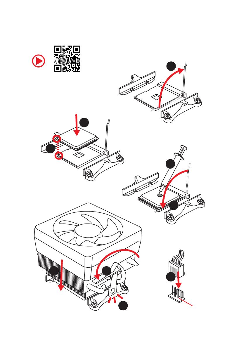
Installing a Processor/ Installation des Prozessors/ Installer un
processeur/ Установка процессора
1
2
3
6
4
5
7
8
9
CPU_FAN1
III
Quick Start
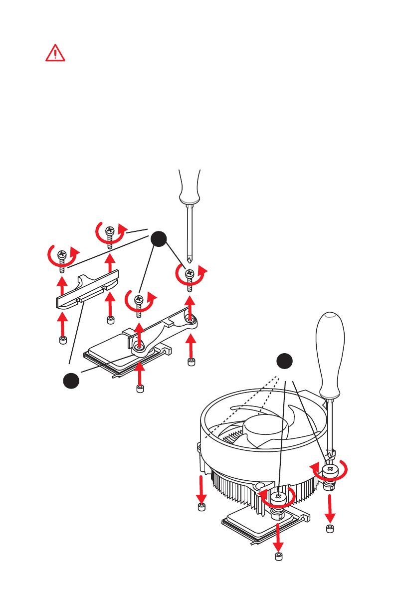
If you are installing the screw-type CPU heatsink, please follow the figure below
to remove the retention module first and then install the heatsink.
Wenn Sie einen CPU-Kühler mit Schraubenbefestigung einsetzen, folgen Sie bitte
den Anweisungen unten um das Retention-Modul zu entfernen und den Kühler zu
installieren.
Si vous voulez installer un ventirad pour processeur à vis, veuillez suivre les
instructions ci-dessous pour d’abord retirer le module de rétention puis installer le
ventirad.
В случае установки процессорного кулера с системой крепления на винтах,
следуйте указаниям на рисунке ниже для снятия пластикового модуля
крепления. Затем установите кулер.
1
2
3
IV
Quick Start
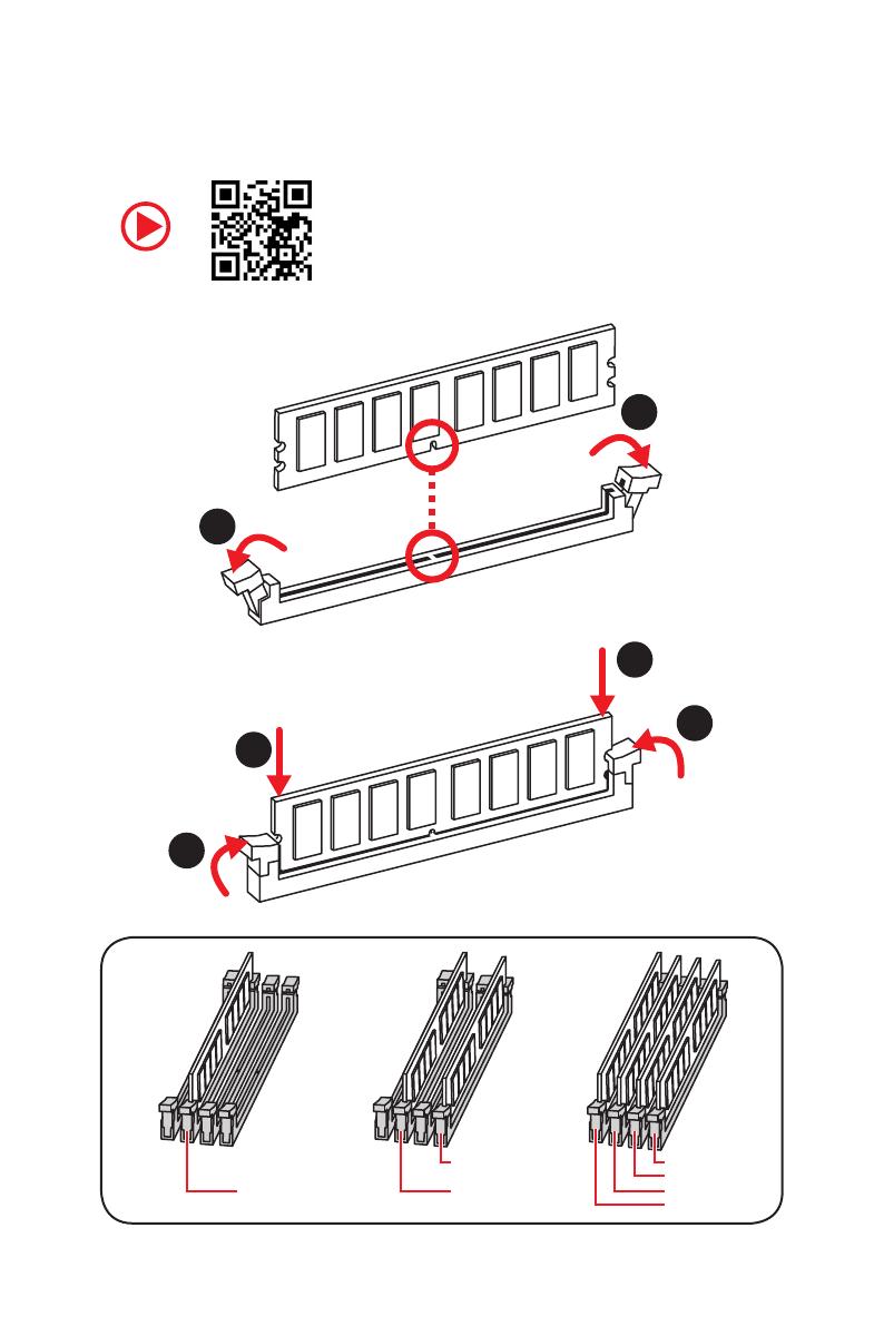
Installing DDR4 memory/ Installation des DDR4-Speichers/
Installer une mémoire DDR4/ Установка памяти DDR4
DIMMB2 DIMMB2
DIMMB1
DIMMA2 DIMMA2 DIMMA2
DIMMA1
1
1
2
2
3
3
V
Quick Start
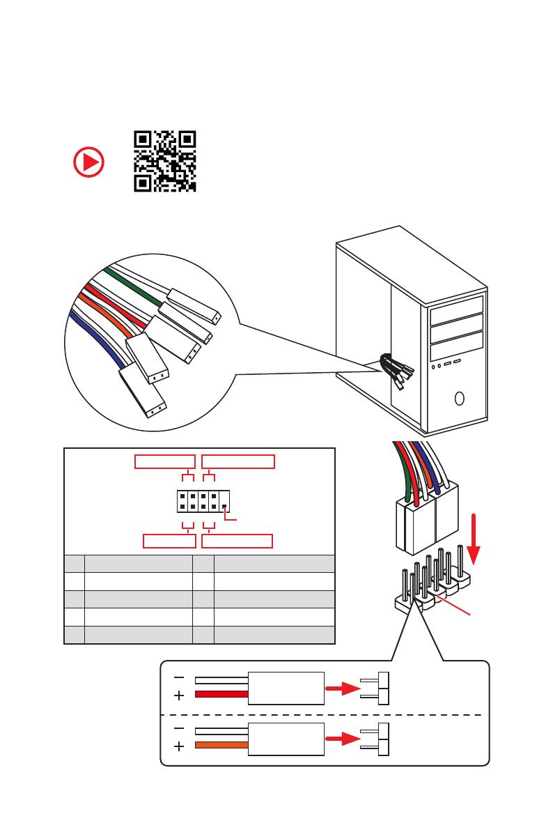
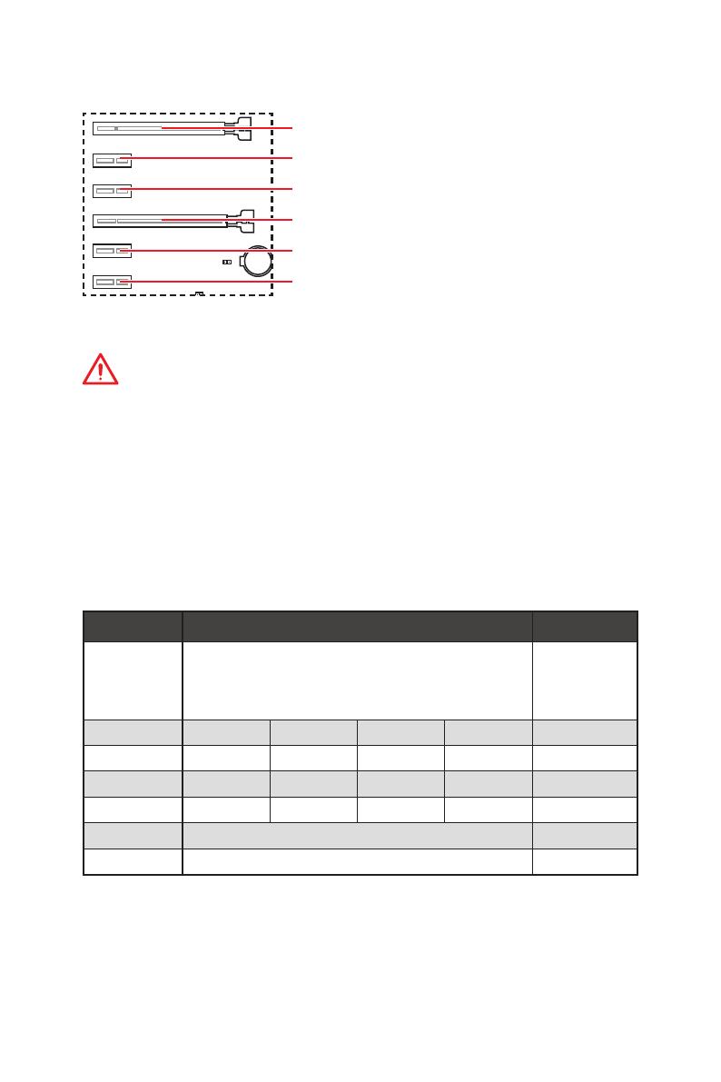
Connecting the Front Panel Header/ Anschließen der
Frontpanel-Stiftleiste/ Connecter un connecteur du panneau
avant/ Подключение разъемов передней панели
RESET SW
POWER SW
POWER LED+
POWER LED-
HDD LED
HDD LED
RESET SW
JFP1
HDD LED
HDD LED —
HDD LED +
POWER LED —
POWER LED +
POWER LED
1
2 10
9
+
+
+—
——
—
+
Power LED
HDD LED Reset Switch
Reserved
Power Switch
JFP1
1 HDD LED + 2 Power LED +
3 HDD LED — 4 Power LED —
5 Reset Switch 6 Power Switch
7 Reset Switch 8 Power Switch
9 Reserved 10 No Pin
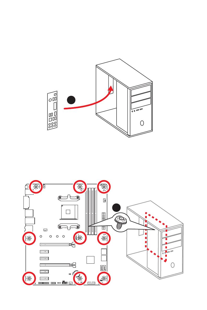
VI
Quick Start
Installing the Motherboard/ Installation des Motherboards/
Installer la carte mère/ Установка материнской платы
BAT1
1
2
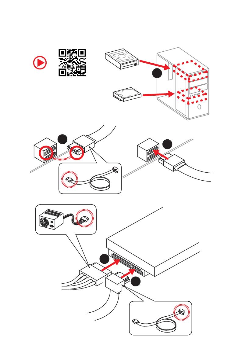
VII
Quick Start
1
2
3
4
5
Installing SATA Drives/ Installation der SATA-Laufwerke/
Installer le disque dur SATA/ Установка дисков SATA
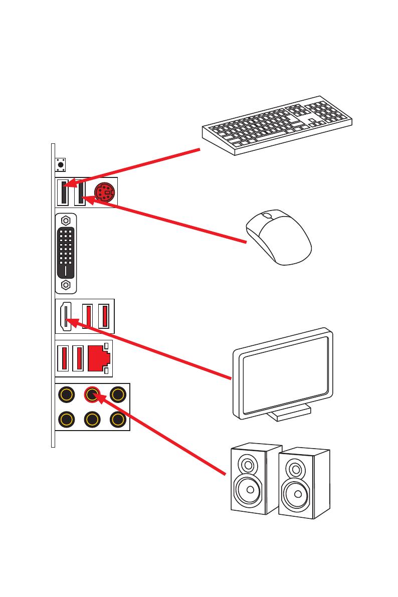
IX
Quick Start
Connecting Peripheral Devices/ Peripheriegeräte/
Connecter un périphérique anschliessen/ Подключение
периферийных устройств
Ryzen™ with Radeon Vega
Graphics Processors
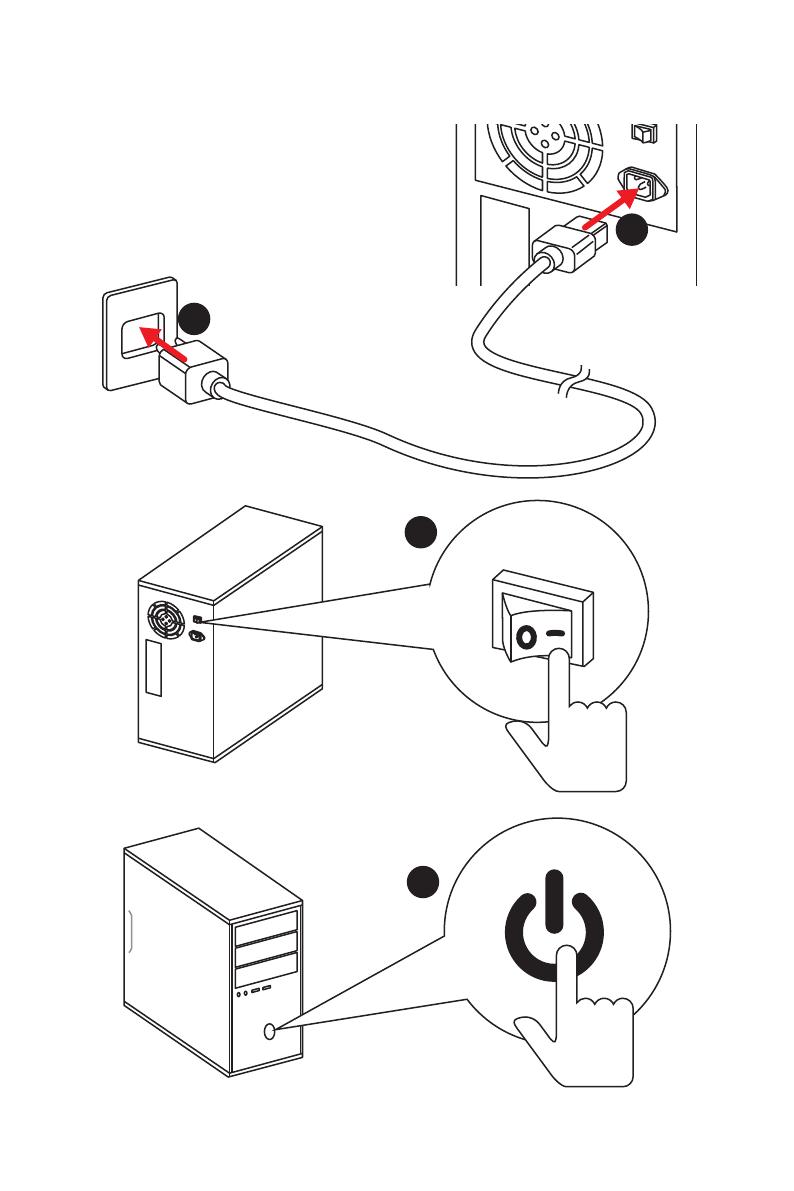
XI
Quick Start
Power On/ Einschalten/ Mettre sous-tension/ Включение
питания
1
4
2
3

4
Specifications
Continued from previous page
Storage
AMD
®
CPU
y 2x SATA 6Gb/s ports*
y 1x M.2 slot (Key M)*
Supports PCIe 3.0 x4 and SATA 6Gb/s 2242/ 2260 /2280/
22110 storage devices
AMD
®
B450 Chipset
y 4x SATA 6Gb/s ports
* SATA5 and SATA6 ports will be unavailable when installing a M.2 device in M.2
slot.
RAID
AMD
®
B450 Chipset
y Supports RAID 0, RAID1 and RAID 10 for SATA storage
devices
USB
y AMD
®
B450 Chipset
2x USB 3.1 Gen2 (SuperSpeed USB 10Gbps) Type-A
ports on the back panel
2x USB 3.1 Gen1 (SuperSpeed USB) ports available
through the internal USB 3.1 Gen1 connector
6x USB 2.0 (High-speed USB) ports (2 Type-A ports on
the back panel, 4 ports available through the internal
USB 2.0 connectors)
y AMD
®
CPU
2x USB 3.1 Gen1 (SuperSpeed USB) Type-A ports on the
back panel
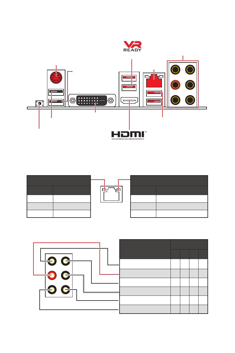
Back Panel
Connectors
y 1x Flash BIOS button
y 1x PS/2 keyboard/ mouse combo port
y 2x USB 2.0 Type-A ports
y 1x DVI-D port
y 1x HDMI
™
port
y 2x USB 3.1 Gen1 Type-A ports
y 1x LAN (RJ45) port
y 2x USB 3.1 Gen2 Type-A ports
y 6x audio jacks
Continued on next page
8
Rear I/O Panel
Link/ Activity LED
Status Description
Off No link
Yellow Linked
Blinking Data activity
Speed LED
Status Description
Off 10 Mbps connection
Green 100 Mbps connection
Orange 1 Gbps connection
LAN Port LED Status Table
Audio Ports Configuration
Audio Ports
Channel
2 4 6 8
Line-In
Line-Out/ Front Speaker Out ● ● ● ●
Rear Speaker Out ● ● ●
Center/ Subwoofer Out ● ●
Side Speaker Out ●
Mic In
(●: connected, Blank: empty)
Rear I/O Panel
PS/2
LAN
USB 2.0 Type-A
Audio Ports
DVI-D
USB 3.1 Gen1 Type-A
USB 3.1 Gen2
Type-A
Flash BIOS button
y Flash BIOS port/ button — Please refer to page 25 for Updating BIOS with Flash BIOS
button.
Flash BIOS port
10
Rear I/O Panel
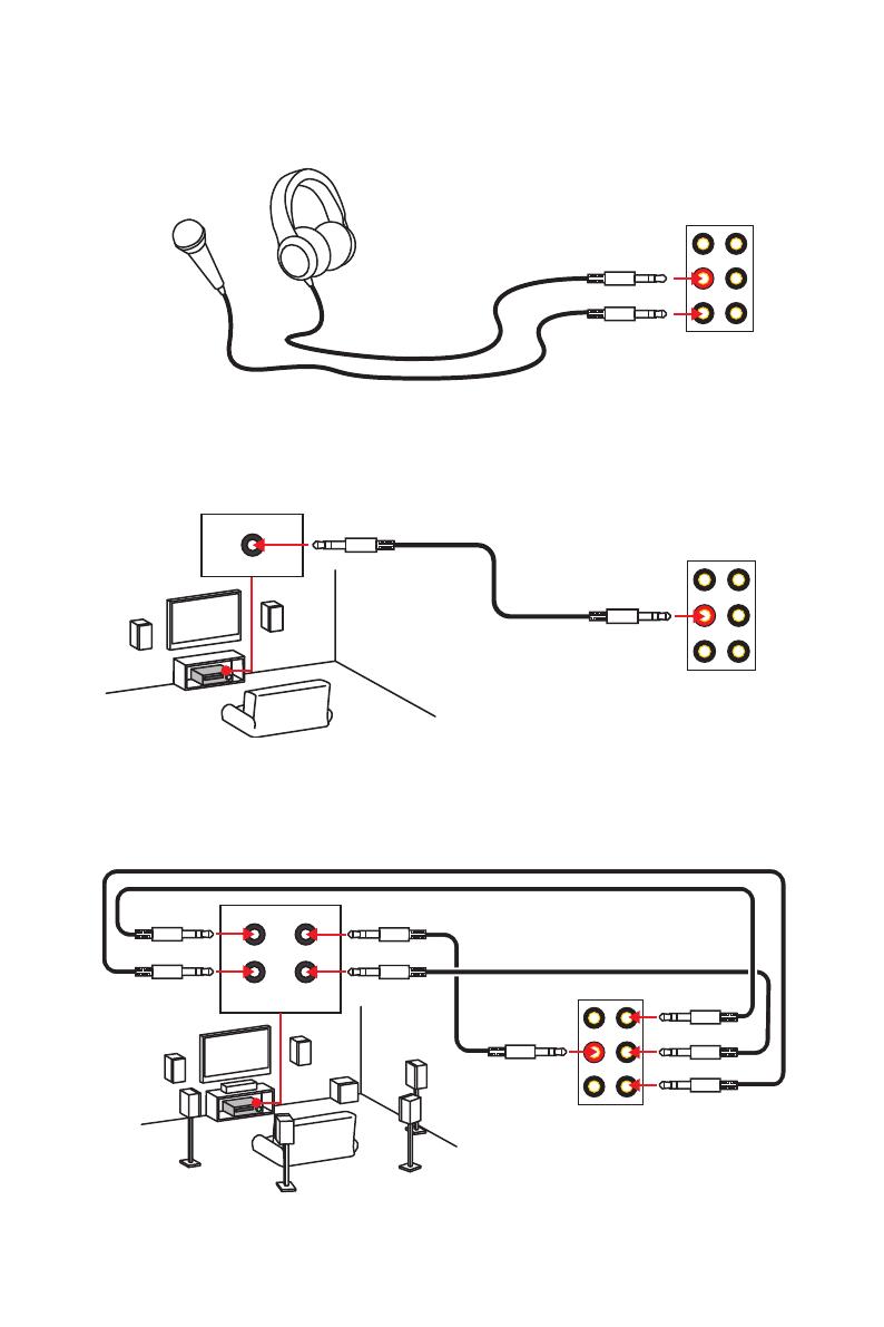
Audio jacks to headphone and microphone diagram
Audio jacks to stereo speakers diagram
Audio jacks to 7.1-channel speakers diagram
AUDIO INPUT
Rear Front
Side Center/
Subwoofer
AUDIO INPUT
11
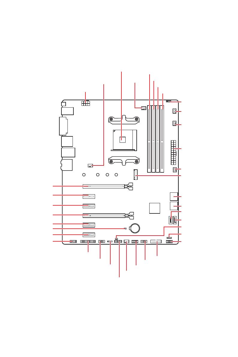
Overview of Components
BAT1
Overview of Components
JLPT1
SATA▼5▲6
SATA▼3▲4
CPU_FAN1
SYS_FAN1
PUMP_FAN1
JRGB1
PCI_E1
PCI_E2
PCI_E3
PCI_E4
PCI_E5
PCI_E6
JBAT1
JAUD1
JTPM1
Processor
Socket
CPU_PWR1
DIMMA1
SYS_FAN4
M2_1
DIMMA2
DIMMB1
DIMMB2
JUSB3
JUSB2
JUSB1
SATA1
JCI1
JFP1
SATA2
JFP2
JRGB2
SYS_FAN2
JCOM1
ATX_PWR1
SYS_FAN3
14
Overview of Components
BAT1
PCI_E1~6: PCIe Expansion Slots
PCI_E1: PCIe 3.0 x16*/ PCIe 3.0 x8**
PCI_E2: PCIe 2.0 x1
PCI_E3: PCIe 2.0 x1
PCI_E4: PCIe 2.0 x4
PCI_E5: PCIe 2.0 x1
PCI_E6: PCIe 2.0 x1
Important
y
If you install a large and heavy graphics card, you need to use a tool such as MSI
Gaming Series Graphics Card Bolster to support its weight to prevent deformation of
the slot.
y
For a single PCIe x16 expansion card installation with optimum performance, using
the PCI_E1 slot is recommended.
y
When adding or removing expansion cards, always turn off the power supply and
unplug the power supply power cable from the power outlet. Read the expansion
card’s documentation to check for any necessary additional hardware or software
changes.
y
PCI_E4 will run x1 speed when installing devices in PCI_E2/ PCI_E3/ PCI_E5 slot.
* For Ryzen™ 1st and 2nd Generation processors
** For Ryzen™ with Radeon Vega Graphics processors
PCIe bandwidth of Multiple graphics cards
Slot Single 2-Way
PCI_E1 (CPU)
3.0 x16*
/1
or
3.0 x8*
/2
3.0 x16*
/1
or
3.0 x8*
/2
PCI_E2 (PCH) 2.0 x1 2.0 x1 Empty Empty ―
PCI_E3 (PCH) 2.0 x1 Empty 2.0 x1 Empty ―
PCI_E4 (PCH) 2.0 x1 2.0 x1 2.0 x1 2.0 x1 2.0 x4*
PCI_E5 (PCH) 2.0 x1 Empty Empty 2.0 x1 ―
PCI_E6 (PCH) 2.0 x1 2.0×1
M2_1 (CPU) 3.0 x4 3.0 x4
(─: unavailable, *: graphics card,
1
: for Ryzen™ 1st and 2nd Generation processors,
2
: for Ryzen™ with Radeon Vega Graphics processors)
17
Overview of Components
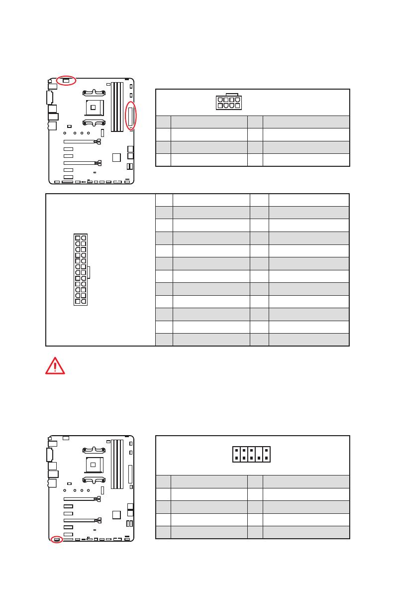
24
131
12
ATX_PWR1
1 +3.3V 13 +3.3V
2 +3.3V 14 -12V
3 Ground 15 Ground
4 +5V 16 PS-ON#
5 Ground 17 Ground
6 +5V 18 Ground
7 Ground 19 Ground
8 PWR OK 20 Res
9 5VSB 21 +5V
10 +12V 22 +5V
11 +12V 23 +5V
12 +3.3V 24 Ground
5
4 1
8
CPU_PWR1
1 Ground 5 +12V
2 Ground 6 +12V
3 Ground 7 +12V
4 Ground 8 +12V
Important
Make sure that all the power cables are securely connected to a proper ATX power
supply to ensure stable operation of the motherboard.
CPU_PWR1, ATX_PWR1: Power Connectors
These connectors allow you to connect an ATX power supply.
JAUD1: Front Audio Connector
This connector allows you to connect audio jacks on the front panel.
1
2 10
9
1 MIC L 2 Ground
3 MIC R 4 NC
5 Head Phone R 6 MIC Detection
7 SENSE_SEND 8 No Pin
9 Head Phone L 10 Head Phone Detection
18
Overview of Components
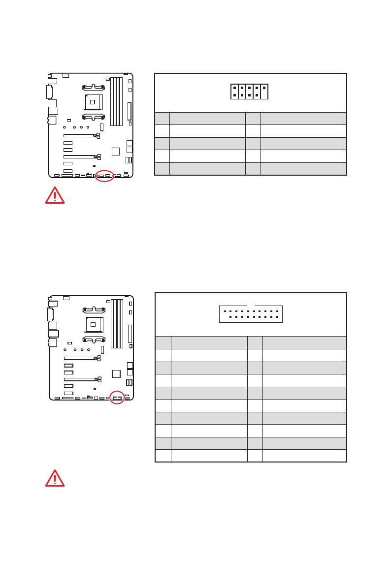
JUSB1~2: USB 2.0 Connectors
These connectors allow you to connect USB 2.0 ports on the front panel.
1
2 10
9
1 VCC 2 VCC
3 USB0- 4 USB1-
5 USB0+ 6 USB1+
7 Ground 8 Ground
9 No Pin 10 NC
Important
y
Note that the VCC and Ground pins must be connected correctly to avoid possible
damage.
y
In order to recharge your iPad,iPhone and iPod through USB ports, please install
MSI
®
SUPER CHARGER utility.
JUSB3: USB 3.1 Gen1 Connector
This connector allows you to connect USB 3.1 Gen1 ports on the front panel.
Important
Note that the Power and Ground pins must be connected correctly to avoid possible
damage.
1
10
11
20
1 Power 11 USB2.0+
2 USB3_RX_DN 12 USB2.0-
3 USB3_RX_DP 13 Ground
4 Ground 14 USB3_TX_C_DP
5 USB3_TX_C_DN 15 USB3_TX_C_DN
6 USB3_TX_C_DP 16 Ground
7 Ground 17 USB3_RX_DP
8 USB2.0- 18 USB3_RX_DN
9 USB2.0+ 19 Power
10 NC 20 No Pin
20
Overview of Components
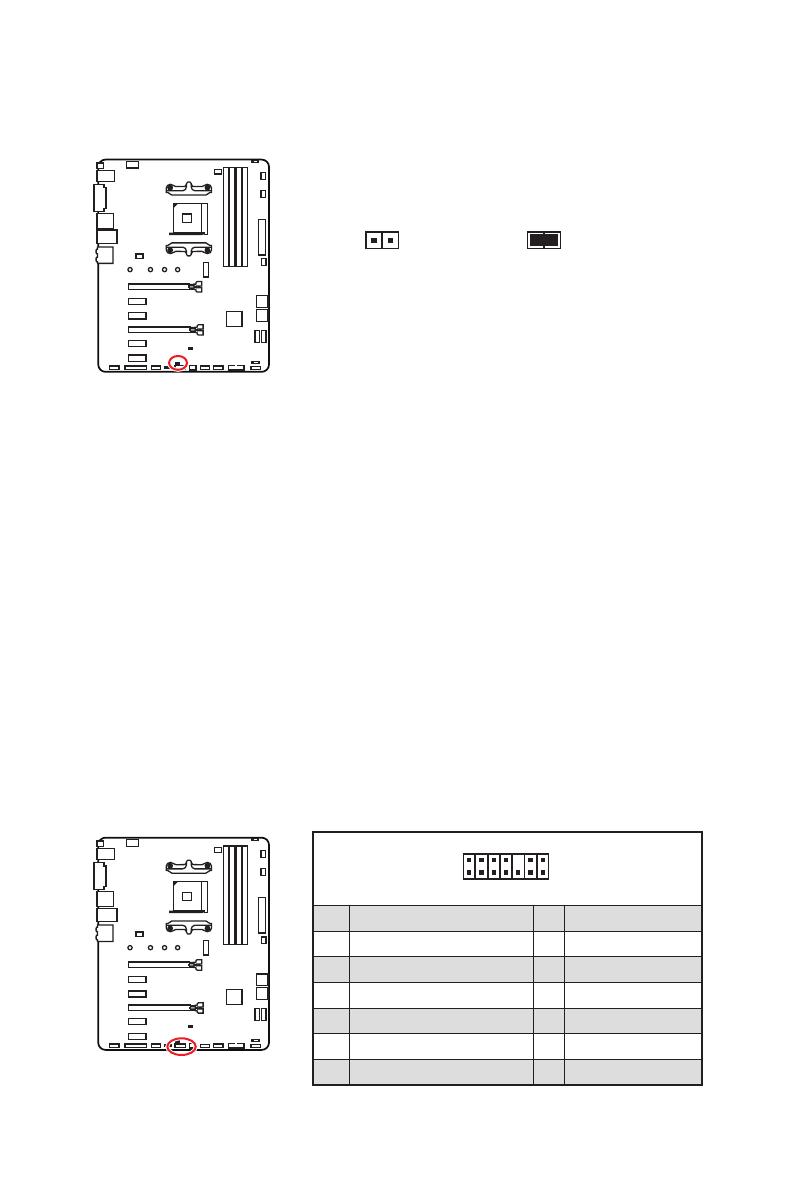
JCI1: Chassis Intrusion Connector
This connector allows you to connect the chassis intrusion switch cable.
Normal
(default)
Trigger the chassis
intrusion event
Using chassis intrusion detector
1. Connect the JCI1 connector to the chassis intrusion switch/ sensor on the chassis.
2. Close the chassis cover.
3. Go to BIOS > SETTINGS > Security > Chassis Intrusion Configuration.
4. Set Chassis Intrusion to Enabled.
5. Press F10 to save and exit and then press the Enter key to select Yes.
6. Once the chassis cover is opened again, a warning message will be displayed on
screen when the computer is turned on.
Resetting the chassis intrusion warning
1. Go to BIOS > SETTINGS > Security > Chassis Intrusion Configuration.
2. Set Chassis Intrusion to Reset.
3. Press F10 to save and exit and then press the Enter key to select Yes.
1
2 14
13
1 LPC Clock 2 3V Standby power
3 LPC Reset 4 3.3V Power
5 LPC address & data pin0 6 Serial IRQ
7 LPC address & data pin1 8 5V Power
9 LPC address & data pin2 10 No Pin
11 LPC address & data pin3 12 Ground
13 LPC Frame 14 Ground
JTPM1: TPM Module Connector
This connector is for TPM (Trusted Platform Module). Please refer to the TPM security
platform manual for more details and usages.
21
Overview of Components
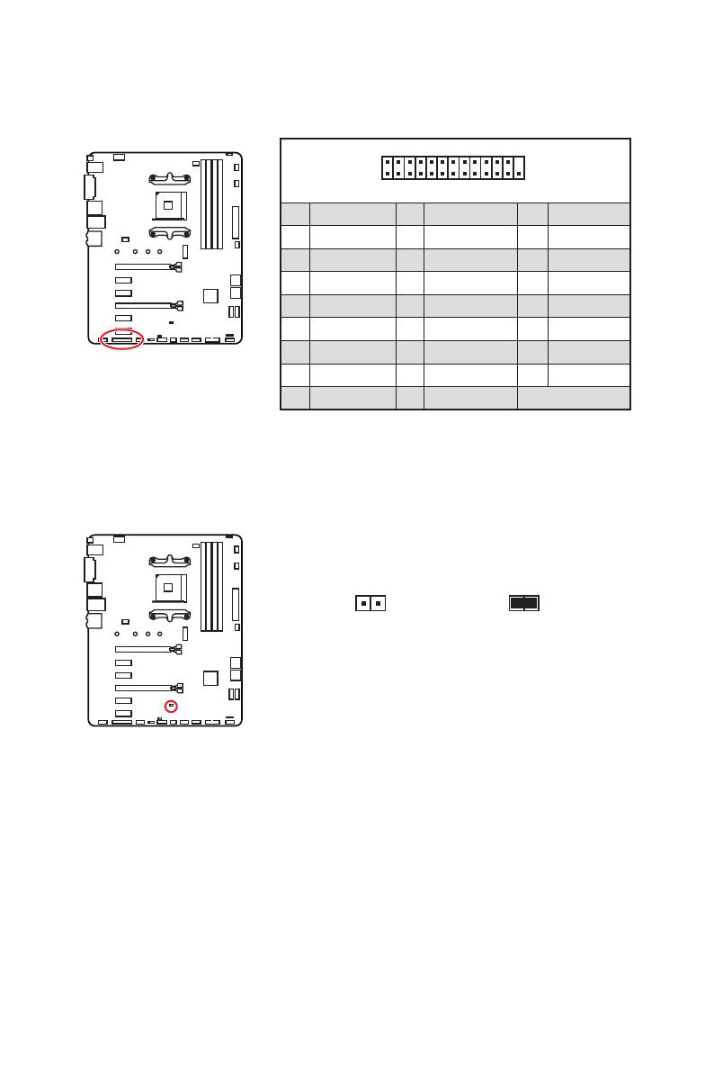
1
2 26
25
1 RSTB# 2 AFD# 3 PRND0
4 ERR# 5 PRND1 6 PINIT#
7 PRND2 8 LPT_SLIN# 9 PRND3
10 Ground 11 PRND4 12 Ground
13 PRND5 14 Ground 15 PRND6
16 Ground 17 PRND7 18 Ground
19 ACK# 20 Ground 21 BUSY
22 Ground 23 PE 24 Ground
25 SLCT 26 No Pin
JLPT1: Parallel Port Connector
This connector allows you to connect the optional parallel port with bracket.
JBAT1: Clear CMOS (Reset BIOS) Jumper
There is CMOS memory onboard that is external powered from a battery located on
the motherboard to save system configuration data. If you want to clear the system
configuration, set the jumper to clear the CMOS memory.
Keep Data
(default)
Clear CMOS/
Reset BIOS
Resetting BIOS to default values
1. Power off the computer and unplug the power cord.
2. Use a jumper cap to short JBAT1 for about 5-10 seconds.
3. Remove the jumper cap from JBAT1.
4. Plug the power cord and Power on the computer.


10
Rückseite E/A
Audiobuchsen für den Anschluss von einem Kopfhörer und Mikrofon
Audiobuchsen für Stereo-Lautsprecher
Audiobuchsen für 7.1 Kanal Anlage
AUDIO INPUT
Rear Front
Side Center/
Subwoofer
AUDIO INPUT
/

- Manuals
- Brands
- Gigabyte Manuals
- Motherboard
- B450 GAMING X
- User manual
-
Contents
-
Table of Contents
-
Bookmarks
Quick Links
B450 GAMING X
User’s Manual
Rev. 1001
12ME-B45GMX-1001R
For more product details, please visit GIGABYTE’s website.
To reduce the impacts on global warming, the packaging materials of this product
are recyclable and reusable. GIGABYTE works with you to protect the environment.
Related Manuals for Gigabyte B450 GAMING X
Summary of Contents for Gigabyte B450 GAMING X
-
Page 1
B450 GAMING X User’s Manual Rev. 1001 12ME-B45GMX-1001R For more product details, please visit GIGABYTE’s website. To reduce the impacts on global warming, the packaging materials of this product are recyclable and reusable. GIGABYTE works with you to protect the environment. -
Page 2
Information in this manual is protected by copyright laws and is the property of GIGABYTE. Changes to the specifications and features in this manual may be made by GIGABYTE without prior notice. No part of this manual may be reproduced, copied, translated, transmitted, or published in any form or by any means without GIGABYTE’s prior written permission. -
Page 3: Table Of Contents
Table of Contents B450 GAMING X Motherboard Layout …………….4 Chapter 1 Hardware Installation ………………5 Installation Precautions ………………5 1-2 Product Specifications ………………6 Installing the CPU ……………….. 9 Installing the Memory ………………9 Installing an Expansion Card …………….. 10 Back Panel Connectors ……………… 10 Internal Connectors ………………
-
Page 4: B450 Gaming X Motherboard Layout
B450 GAMING X Motherboard Layout ATX_12V KB_MS_USB CPU_FAN Socket AM4 R_USB30 USB_LAN SYS_FAN1 LED_CPU AUDIO M_BIOS PCIEX1_1 B450 GAMING X PCIEX16 Realtek ® GbE LAN AMD B450 PCIEX4 CODEC SATA3 1 0 ® Super I/O PCIEX1_2 SPDIF_O F_USB1 CLR_CMOS SYS_FAN3 F_AUDIO…
-
Page 5: Chapter 1 Hardware Installation
Chapter 1 Hardware Installation Installation Precautions The motherboard contains numerous delicate electronic circuits and components which can become damaged as a result of electrostatic discharge (ESD). Prior to installation, carefully read the user’s manual and follow these procedures: • Prior to installation, make sure the chassis is suitable for the motherboard. • Prior to installation, do not remove or break motherboard S/N (Serial Number) sticker or warranty sticker provided by your dealer.
-
Page 6: 1-2 Product Specifications
Š S upport for ECC Un-buffered DIMM 1Rx8/2Rx8 memory modules (operate in Š non-ECC mode) Support for non-ECC Un-buffered DIMM 1Rx8/2Rx8/1Rx16 memory modules Š Support for Extreme Memory Profile (XMP) memory modules Š (Go to GIGABYTE’s website for the latest supported memory speeds and memory modules.) Onboard Integrated Graphics Processor: Š Graphics (Note) 1 x DVI-D port, supporting a maximum resolution of 1920×1200@60 Hz * The DVI-D port does not support D-Sub connection by adapter.
-
Page 7
Storage Interface Š 1 x M.2 connector (Socket 3, M key, type 2242/2260/2280/22110 PCIe 3.0 x4/ x2 SSD support) 6 x SATA 6Gb/s connectors Š Support for RAID 0, RAID 1, and RAID 10 Š * R efer to «1-7 Internal Connectors,» for the installation notices for the M.2 and SATA connectors. Chipset: Š 2 x USB 3.1 Gen 1 ports available through the internal USB header 6 x USB 2.0/1.1 ports (4 ports on the back panel, 2 ports available through the internal USB header) Integrated in the APU:… -
Page 8
ATX Form Factor; 30.5cm x 23.5cm Š * GIGABYTE reserves the right to make any changes to the product specifications and product-related information without prior notice. Please visit the SupportUtility List Please visit GIGABYTE’s website for support lists of CPU, memory page on GIGABYTE’s website to modules, SSDs, and M.2 devices. download the latest version of apps. — 8 -… -
Page 9: Installing The Cpu
The four memory sockets are divided into two channels and each channel has two memory sockets as following: Channel A: DDR4_2, DDR4_4 Channel B: DDR4_1, DDR4_3 Dual Channel Memory Configurations Table DDR4_4 DDR4_2 DDR4_3 DDR4_1 2 Modules DS/SS DS/SS DS/SS DS/SS 4 Modules DS/SS DS/SS DS/SS DS/SS (SS=Single-Sided, DS=Double-Sided, «- -«=No Memory) Please visit GIGABYTE’s website for details on hardware installation. — 9 -…
-
Page 10: Installing An Expansion Card
Due to CPU limitations, read the following guidelines before installing the memory in Dual Channel mode. Dual Channel mode cannot be enabled if only one memory module is installed. When enabling Dual Channel mode with two or four memory modules, it is recommended that memory of the same capacity, brand, speed, and chips be used. For optimum performance, when enabling Dual Channel mode with two memory modules, we recommend that you install them in the DDR4_1 and DDR4_2 sockets. Installing an Expansion Card Read the following guidelines before you begin to install an expansion card: • Make sure the motherboard supports the expansion card. Carefully read the manual that came with your expansion card.
-
Page 11
Center/Subwoofer Speaker Out Rear Speaker Out Side Speaker Out Line In Line Out/Front Speaker Out Mic In To enable or configure the audio amplifying function for the Line out jack, please access the HD Audio Manager application. • When removing the cable connected to a back panel connector, first remove the cable from your device and then remove it from the motherboard. • When removing the cable, pull it straight out from the connector. Do not rock it side to side to prevent an electrical short inside the cable connector. Please visit GIGABYTE’s website for details on configuring the audio software. — 11 -… -
Page 12: Internal Connectors
Internal Connectors ATX_12V SPDIF_O F_PANEL CPU_FAN F_AUDIO SYS_FAN1/2/3 LED_CPU CLR_CMOS LED_C F_USB30 D_LED1/D_LED2 F_USB1 ASATA3 0/1 COMA SATA3 0/1/2/3 M2A_SOCKET Read the following guidelines before connecting external devices: • First make sure your devices are compliant with the connectors you wish to connect. • Before installing the devices, be sure to turn off the devices and your computer. Unplug the power cord from the power outlet to prevent damage to the devices.
-
Page 13
1/2) ATX_12V/ATX (2×4 12V Power Connector and 2×12 Main Power Connector) With the use of the power connector, the power supply can supply enough stable power to all the components on the motherboard. Before connecting the power connector, first make sure the power supply is turned off and all devices are properly installed. The power connector possesses a foolproof design. Connect the power supply cable to the power connector in the correct orientation. -
Page 14
Connect your RGB LED strip to the header. The power pin (marked RGB LED Strip with a triangle on the plug) of the LED strip must be connected to Pin 1 (12V) of the addressable LED strip header. Incorrect connection may lead to the damage of the LED strip. For how to turn on/off the lights of the LED strip please visit the «Unique Features» webpage of GIGABYTE’s website. Before installing the devices, be sure to turn off the devices and your computer. Unplug the power cord from the power outlet to prevent damage to the devices. — 14 -… -
Page 15
7) D_LED1/D_LED2 (Addressable LED Strip Headers) The headers can be used to connect a standard 5050 addressable LED strip, with maximum power rating of 2A (5V) and maximum length of 5m or maximum number of 1000 LEDs. Pin No. Definition No Pin D_LED1 D_LED2 Connect your addressable LED strip to the header. The power pin Addressable (marked with a triangle on the plug) of the LED strip must be connected LED Strip to Pin 1 of the addressable LED strip header. Incorrect connection may lead to the damage of the LED strip. For how to turn on/off the lights of the LED strip, refer to the instructions on in Chapter 2, «BIOS Setup,» «Peripherals.» Before installing the devices, be sure to turn off the devices and your computer. Unplug the power DEBUG cord from the power outlet to prevent damage to the devices. -
Page 16
10) M2A_SOCKET/M2B_SOCKET (M.2 Socket 3 Connectors) The M.2 connectors support M.2 SATA SSDs or M.2 PCIe SSDs and support RAID configuration. (Note) Please note that an M.2 PCIe SSD cannot be used to create a RAID set either with an M.2 SATA SSD or a SATA hard drive. To create a RAID array with an M.2 PCIe SSD, you must set up the configuration in UEFI BIOS mode. Refer to Chapter 3, «Configuring a RAID Set,» for instructions on configuring a RAID array. Follow the steps below to correctly install an M.2 SSD in the M.2 connector. Step 1: Use a screw driver to unfasten the screw and nut from the motherboard. Locate the proper mounting hole for the M.2 SSD to be installed and then screw the nut first. Step 2: Slide the M.2 SSD into the connector at an angle. Step 3: Press the M.2 SSD down and then secure it with the screw. Select the proper hole for the M.2 SSD to be installed and refasten the screw and nut. -
Page 17
11) SPDIF_O (S/PDIF Out Header) This header supports digital S/PDIF Out and connects a S/PDIF digital audio cable (provided by expansion cards) for digital audio output from your motherboard to certain expansion cards like graphics cards and sound cards. For example, some graphics cards may require you to use a S/PDIF digital audio cable for digital audio output from your motherboard to your graphics card if you wish to connect an HDMI display to the graphics card and have digital audio output from the HDMI display at the same time. For information about connecting the S/PDIF digital audio cable, carefully read the manual for your expansion card. Pin No. Definition 5VDUAL S F_ No Pin SPDIFO 12) F_PANEL (Front Panel Header) Connect the power switch, reset switch, speaker, chassis intrusion switch/sensor and system status indicator on the chassis to this header according to the pin assignments below. Note the positive and negative pins before connecting the cables. -
Page 18
13) F_AUDIO (Front Panel Audio Header) The front panel audio header supports High Definition audio (HD). You may connect your chassis front panel audio module to this header. Make sure the wire assignments of the module connector match the pin assignments of the motherboard header. Incorrect connection between the module connector and the motherboard header will make the device unable to work or even damage it. Pin No. -
Page 19
16) F_USB30 (USB 3.1 Gen 1 Header) The header conforms to USB 3.1 Gen 1 and USB 2.0 specification and can provide two USB ports. For purchasing the optional 3.5″ front panel that provides two USB 3.1 Gen 1 ports, please contact the local dealer. Pin No. Definition Pin No. Definition VBUS SSRX1- F_USB30 F_ U SSRX1+ SSTX2+ SSTX1- SSTX2- SSTX1+ SSRX2+ SSRX2- VBUS No Pin B S S 17) F_USB1 (USB 2.0/1.1 Headers) The header conforms to USB 2.0/1.1 specification. Each USB header can provide two USB ports via an optional USB bracket. -
Page 20
B S S 19) TPM (Trusted Platform Module Header) You may connect a TPM (Trusted Platform Module) to this header. Pin No. Definition Pin No. Definition LCLK LAD0 LFRAME No Pin LRESET SB3V SERIRQ 1 2 3 LAD3 LAD2 VCC3 LAD1 B S S S F_ — 20 -… -
Page 21: Chapter 2 Bios Setup
BIOS includes a BIOS Setup program that allows the user to modify basic system configuration settings or to activate certain system features. When the power is turned off, the battery on the motherboard supplies the necessary power to the CMOS to keep the configuration values in the CMOS. To access the BIOS Setup program, press the <Delete> key during the POST when the power is turned on. To upgrade the BIOS, use either the GIGABYTE Q-Flash or @BIOS utility. Q-Flash allows the user to quickly and easily upgrade or back up BIOS without entering the operating system. • @BIOS is a Windows-based utility that searches and downloads the latest version of BIOS from the Internet •…
-
Page 22: The Main Menu
The Main Menu System Time Setup Menus Hardware Information Configuration Items Current Settings Quick Access Bar allows you to enter Easy Mode, select BIOS default language, configure fan settings, or enter Q-Flash. Classic Setup Function Keys <f><g> Move the selection bar to select a setup menu <h><i> Move the selection bar to select an configuration item on a menu <Enter> Execute command or enter a menu < + >/<Page Up> Increase the numeric value or make changes <…
-
Page 23
M.I.T. Whether the system will work stably with the overclock/overvoltage settings you made is dependent on your overall system configurations. Incorrectly doing overclock/overvoltage may result in damage to CPU, chipset, or memory and reduce the useful life of these components. This page is for advanced users only and we recommend you not to alter the default settings to prevent system instability or other unexpected results. -
Page 24
` Advanced CPU Core Settings & CPU Clock Ratio, CPU Frequency The settings above are synchronous to those under the same items on the Advanced Frequency Settings menu. & Core Performance Boost Allows you to determine whether to enable the Core Performance Boost (CPB) technology, a CPU performance-boost technology. (Default: Auto) &… -
Page 25
` Advanced Memory Settings & Extreme Memory Profile (X.M.P.) , System Memory Multiplier, Memory Frequency(Mhz) (Note) The settings above are synchronous to those under the same items on the Advanced Frequency Settings menu. & Memory Timing Mode Manual allows the memory timing settings below to be configurable. Options are: Auto (default), Manual. & Profile DDR Voltage When using a non-XMP memory module or Extreme Memory Profile (X.M.P.) is set to Disabled, the value is displayed according to your memory specification. When Extreme Memory Profile (X.M.P.) is set to Profile1 or Profile2, the value is displayed according to the SPD data on the XMP memory. -
Page 26
& Fan Speed Control Allows you to determine whether to enable the fan speed control function and adjust the fan speed. Allows the fan to run at different speeds according to the temperature. You can adjust Normal the fan speed with System Information Viewer based on your system requirements. (Default) Allows the fan to run at slow speeds. Silent Allows you to control the fan speed in the curve graph. -
Page 27: System
System This section provides information on your motherboard model and BIOS version. You can also select the default language used by the BIOS and manually set the system time. & System Language Selects the default language used by the BIOS. &…
-
Page 28: Bios
System program. (Default) & Full Screen LOGO Show Allows you to determine whether to display the GIGABYTE Logo at system startup. Disabled skips the GIGABYTE Logo when the system starts up. (Default: Enabled) & Fast Boot Enables or disables Fast Boot to shorten the OS boot process. Ultra Fast provides the fastest bootup speed. (Default: Disabled)
-
Page 29
& SATA Support All Sata Devices A ll SATA devices are functional in the operating system and during the POST. Last Boot HDD Only E xcept for the previous boot drive, all SATA devices are disabled before the OS boot process completes. (Default) This item is configurable only when Fast Boot is set to Enabled or Ultra Fast. & VGA Support Allows you to select which type of operating system to boot. Auto Enables legacy option ROM only. EFI Driver Enables EFI option ROM. (Default) This item is configurable only when Fast Boot is set to Enabled or Ultra Fast. &… -
Page 30
& Administrator Password Allows you to configure an administrator password. Press <Enter> on this item, type the password, and then press <Enter>. You will be requested to confirm the password. Type the password again and press <Enter>. You must enter the administrator password (or user password) at system startup and when entering BIOS Setup. Differing from the user password, the administrator password allows you to make changes to all BIOS settings. & User Password Allows you to configure a user password. Press <Enter> on this item, type the password, and then press <Enter>. You will be requested to confirm the password. Type the password again and press <Enter>. You must enter the administrator password (or user password) at system startup and when entering BIOS Setup. However, the user password only allows you to make changes to certain BIOS settings but not all. To cancel the password, press <Enter> on the password item and when requested for the password, enter the correct one first. When prompted for a new password, press <Enter> without entering any password. Press <Enter> again when prompted to confirm. NOTE: Before setting the User Password, be sure to set the Administrator Password first. & Secure Boot Allows you to enable or disable Secure Boot and configure related settings. This item is configurable only when CSM Support is set to Disabled. -
Page 31: Peripherals
Peripherals & AMD CPU fTPM Enables or disables the TPM 2.0 function integrated in the AMD CPU. (Default: Disabled) & Initial Display Output Specifies the first initiation of the monitor display from the installed PCI Express graphics card or the onboard graphics. Sets the onboard graphics as the first display. (Note) IGD Video Sets the graphics card on the PCIEX16 slot as the first display. (Default) PCIe 1 Slot Sets the graphics card on the PCIEX4 slot as the first display. PCIe 2 Slot & LEDs in System Power On State Allows you to enable or disable motherboard LED lighting when the system is on. Disables the selected lighting mode when the system is on. Off Enables the selected lighting mode when the system is on. (Default) On & LEDs in Sleep, Hibernation, and Soft Off States Allows you to set the lighting mode of the motherboard LEDs in system S3/S4/S5 state.
-
Page 32
` Trusted Computing Enables or disables Trusted Platform Module (TPM). ` Super IO Configuration & Serial Port 1 Enables or disables the onboard serial port. (Default: Enabled) ` USB Configuration & Legacy USB Support Allows USB keyboard/mouse to be used in MS-DOS. (Default: Enabled) & XHCI Hand-off Determines whether to enable XHCI Hand-off feature for an operating system without XHCI Hand-off support. (Default: Enabled) & USB Mass Storage Driver Support Enables or disables support for USB storage devices. (Default: Enabled) &… -
Page 33
& Media detect count Allows you to set the number of times to check the presence of media. This item is configurable only when Network Stack is enabled. (Default: 1) ` AMD CBS This sub-menu provides AMD CBS-related configuration options. ` Realtek PCIe GBE Family Controller This sub-menu provides information on LAN configuration and related configuration options. — 33 -… -
Page 34: Chipset
Chipset & IOMMU Enables or disables AMD IOMMU support. (Default: Auto) & Integrated Graphics (Note) Enables or disables the onboard graphics function. The BIOS will automatically enable or disable the onboard graphics depending on the Auto graphics card being installed. (Default) Enables the onboard graphics. Forces Disabled Disables the onboard graphics. & UMA Mode (Note) Specify the UMA mode.
-
Page 35
& SATA Mode Enables or disables RAID for the integrated SATA controllers or configures the SATA controllers to AHCI mode. RAID Enables RAID for the SATA controller. AHCI C onfigures the SATA controllers to AHCI mode. Advanced Host Controller Interface (AHCI) is an interface specification that allows the storage driver to enable advanced Serial ATA features such as Native Command Queuing and hot plug. (Default) & NVMe RAID mode (M2A_SOCKET Connector) Allows you to determine whether to use your M.2 NVMe PCIe SSDs to configure RAID. (Default: Disabled) & APU SATA Port Enable (ASATA3 0, 1 Connectors) Enables or disables the integrated SATA controller(s). (Default: Enabled) & Chipset SATA Port Enable (SATA3 0, 1, 2, 3 Connectors) Enables or disables the integrated SATA controller(s). (Default: Enabled) &… -
Page 36: Power
Power & AC BACK Determines the state of the system after the return of power from an AC power loss. The system returns to its last known awake state upon the return of the AC power. Memory Always On The system is turned on upon the return of the AC power. Always Off T he system stays off upon the return of the AC power. (Default) & Power On By Keyboard Allows the system to be turned on by a PS/2 keyboard wake-up event.
-
Page 37
& Soft-Off by PWR-BTTN Configures the way to turn off the computer in MS-DOS mode using the power button. Instant-Off Press the power button and then the system will be turned off instantly. (Default) P ress and hold the power button for 4 seconds to turn off the system. If the power Delay 4 Sec. button is pressed for less than 4 seconds, the system will enter suspend mode. & Power Loading Enables or disables dummy load. When the power supply is at low load, a self-protection will activate causing it to shutdown or fail. If this occurs, please set to Enabled. Auto lets the BIOS automatically configure this setting. (Default: Auto) &… -
Page 38: Save & Exit
Save & Exit & Save & Exit Setup Press <Enter> on this item and select Yes. This saves the changes to the CMOS and exits the BIOS Setup program. Select No or press <Esc> to return to the BIOS Setup Main Menu. & Exit Without Saving Press <Enter> on this item and select Yes. This exits the BIOS Setup without saving the changes made in BIOS Setup to the CMOS. Select No or press <Esc> to return to the BIOS Setup Main Menu. &…
-
Page 39: Chapter 3 Appendix
Chapter 3 Appendix 3-1 Configuring a RAID Set RAID Levels RAID 0 RAID 1 RAID 10 Minimum Number of ≥2 Hard Drives Array Capacity Number of hard drives * Size of the smallest drive (Number of hard drives/2) * Size of the smallest drive Size of the smallest drive Fault Tolerance Before you begin, please prepare the following items: • At least two SATA hard drives or SSDs (to ensure optimal performance, it is recommended that you (Note 1) use two hard drives with identical model and capacity).
-
Page 40
3. Insert the USB thumb drive and then browse to the location of the driver. The location of the drivers is as follows: Hw10RAIDx64 4. Select AMD-RAID Bottom Device first and click Next to load the driver. Then select AMD-RAID Controller and click Next to load the driver. Finally, continue the OS installation. Please visit GIGABYTE’s website for details on configuring a RAID array. — 40 -… -
Page 41: Drivers Installation
Run.exe program.) «Xpress Install» will automatically scan your system and then list all of the drivers that are recommended to install. You can click the Xpress Install button and «Xpress Install» will install all of the selected drivers. Or click the arrow icon to individually install the drivers you need. Please visit GIGABYTE’s website for Please visit GIGABYTE’s website for more software information. more troubleshooting information. — 41 -…
-
Page 42: Regulatory Statements
Contravention will be prosecuted. We believe that the information contained herein was accurate in all respects at the time of printing. GIGABYTE cannot, however, assume any responsibility for errors or omissions in this text. Also note that the information in this document is subject to change without notice and should not be construed as a commitment by GIGABYTE.
-
Page 43
FCC Notice (U.S.A. Only) This equipment has been tested and found to comply with the limits for a Class B digital device, pursuant to Part 15 of the FCC Rules. These limits are designed to provide reasonable protection against harmful interference in a residential installation. This equipment generates, uses, and can radiate radio frequency energy and, if not installed and used in accordance with the instructions, may cause harmful interference to radio communications. -
Page 44: Contact Us
Contact Us GIGA-BYTE TECHNOLOGY CO., LTD. Address: No.6, Baoqiang Rd., Xindian Dist., New Taipei City 231, Taiwan TEL: +886-2-8912-4000, FAX: +886-2-8912-4005 Tech. and Non-Tech. Support (Sales/Marketing) : https://esupport.gigabyte.com WEB address (English): https://www.gigabyte.com WEB address (Chinese): https://www.gigabyte.com/tw GIGABYTE eSupport • To submit a technical or non-technical (Sales/Marketing) question, please link to: https://esupport.gigabyte.com — 44 -…

I
Quick Start
Quick Start
Thank you for purchasing the MSI
®
B450M MORTAR motherboard.
This Quick Start section provides demonstration diagrams about
how to install your computer. Some of the installations also provide
video demonstrations. Please link to the URL to watch it with the web
browser on your phone or tablet. You may have even link to the URL
by scanning the QR code.
Kurzanleitung
Danke, dass Sie das MSI
®
B450M MORTAR Motherboard gewählt
haben. Dieser Abschnitt der Kurzanleitung bietet eine Demo zur
Installation Ihres Computers. Manche Installationen bieten auch
die Videodemonstrationen. Klicken Sie auf die URL, um diese
Videoanleitung mit Ihrem Browser auf Ihrem Handy oder Table
anzusehen. Oder scannen Sie auch den QR Code mit Ihrem Handy,
um die URL zu öffnen.
Présentation rapide
Merci d’avoir choisi la carte mère MSI
®
B450M MORTAR. Ce manuel
fournit une rapide présentation avec des illustrations explicatives
qui vous aideront à assembler votre ordinateur. Des tutoriels vidéo
sont disponibles pour certaines étapes. Cliquez sur le lien fourni
pour regarder la vidéo sur votre téléphone ou votre tablette. Vous
pouvez également accéder au lien en scannant le QR code qui lui est
associé.
Быстрый старт
Благодарим вас за покупку материнской платы MSI
®
B450M
MORTAR. В этом разделе представлена информация,
которая поможет вам при сборке комьютера. Для некоторых
этапов сборки имеются видеоинструкции. Для просмотра
видео, необходимо открыть соответствующую ссылку в
веб—браузере на вашем телефоне или планшете. Вы также
можете выполнить переход по ссылке, путем сканирования
QR-кода.