- Manuals
- Brands
- Hyundai Manuals
- Automobile
- Starex H-1 2004
- Owner’s manual
-
Contents
-
Table of Contents
-
Bookmarks
Quick Links
Chapters
-
Table of Contents
9 -
Before Driving Your Vehicle
15 -
Instruments and Controls
66 -
Starting and Operating
141 -
In Case of Emergency
173 -
Vehicle Maintenance Requirements
220 -
Do-It Yourself Maintenance
238
Related Manuals for Hyundai Starex H-1 2004
Summary of Contents for Hyundai Starex H-1 2004
-
Page 2
A000A01A-GAT This Owner’s Manual should be considered a part of the car and remain with it when it is sold for the use of the next owner. OWNER’S I.D. ORIGINAL: NAME: ADDRESS: STREET: TOWN: COUNTRY: P.CODE: DATE OF SALE: SUBSEQUENT: NAME: ADDRESS: STREET:… -
Page 3
Specifications HSRFL280 All information in the Owner’s Manual is current at the time of publication. Hyundai reserves the right to make changes at any time as part of our policy of continual product improvement may be carried out. This manual applies to current Hyundai H-1 models and explanations of optional as well as standard equipment… -
Page 4
A020A01P-AAT RESPONSIBILITY FOR MAINTENANCE The maintenance requirements for your new Hyundai are found in Section 6. As the owner, it is your responsibility to see that all maintenance operations specified by the manufacturer are carried out at the appropriate intervals. When the vehicle is used in severe driving conditions, more frequent maintenance is required for some operations. -
Page 5
Hyundai we build is something of which we’re very proud. Your Owner’s Manual will introduce you to the features and operation of your new Hyundai. It is suggested that you read it carefully because the information it contains can contribute greatly to the satisfaction you receive from your new car. -
Page 6
CAUTION: MODIFICATIONS TO YOUR HYUNDAI Modification of components may void the manufacturer’s warranty Your Hyundai should not be modified in any way. Modifications may adversely affect the safety, durability and performance of your Hyundai. Components which are subjected to modification or are added to the vehicle resulting in consequential damage are not covered by the vehicle manufacturer’s warranty. -
Page 7
A090A01A-AAT SAFETY AND VEHICLE DAMAGE WARNING This manual includes information titled as WARNING, CAUTION and NOTE. These titles indicate the following: WARNING: This indicates that a condition may result in harm, serious injury or death to you or other persons if the warning is not heeded. Follow the advice provided with the warning. -
Page 8
Hyundai PARTS Hyundai New Vehicle Limited War- Dealership and Service Center. ranty or any other Hyundai war- 1.What are Hyundai Genuine Parts? ranty. In addition, any damage to or failure of Genuine Hyundai Parts Hyundai Genuine Parts are the same… -
Page 9: Table Of Contents
TABLE OF CONTENTS BEFORE DRIVING YOUR VEHICLE INSTRUMENTS AND CONTROLS STARTING AND OPERATING IN CASE OF EMERGENCY APPEARANCE CARE SECTION VEHICLE MAINTENANCE REQUIRMENTS EMISSION CONTROL SYSTEM DO-IT-YOURSELF MAINTENANCE VEHICLE SPECIFICATIONS INDEX…
-
Page 10
INSTRUMENTS AND CONTROLS (MINIBUS/VAN) B250A01P-GAT HSRFL002-1… -
Page 11
1. Multi-function light switch 13. Headlight leveling device switch (If installed) 2. Seat warmer switch (If installed) 14. ECT switch (Automatic transmission only) 3. Horn/Driver’s side airbag (If installed) 15. Fuel-filler lid release lever 4. Rear heater switch (If installed) 16. -
Page 12
INSTRUMENTS AND CONTROLS (TRUCK) B250B01P-GAT C020A02P-2… -
Page 13
1. Multi-function light switch 10. Headlight leveling device switch (If installed) 2. Horn/Driver’s side airbag (If installed) 11. Engine RPM Adjustment Knob 3. Windshield wiper/Washer switch 12. Heater/Air conditioner control panel 4. Hazard warning switch 13. Cigarette lighter 5. Front fog light switch (If installed) 14. -
Page 14
YOUR VEHICLE AT A GLANCE B255A01P-GAT INDICATOR SYMBOLS ON THE INSTRUMENT CLUSTER SRS (Airbag) Service Reminder Door Ajar Warning Light Indicator Light (If installed) ABS Service Reminder Indicator Light Low Fuel Level Warning Light (If installed) O/D OFF Indicator Light POWER/HOLD Indicator Light (If installed) (Automatic Transmission Only) Turn Signal Indicator Lights… -
Page 15: Before Driving Your Vehicle
BEFORE DRIVING YOUR VEHICLE Before Driving Your Vehicle Safety Checks ….1-2 Running-in Recommendations ……..1-2 Vehicle Identification Number (VIN) ……1-4 Keys…………….1-6 Immobilizer System …………1-6 Illuminated Ignition Switch ……… 1-11 Door …………….1-12 Hold Open Lock System ……….1-13 Central Door Locks………….
-
Page 16: Before Driving Your Vehicle Safety Checks
BEFORE DRIVING YOUR VEHICLE BEFORE DRIVING YOUR RUNNING-IN RECOMMEN- VEHICLE SAFETY CHECKS DATIONS B010A01P-GAT B020A01P-GAT Be sure you know your vehicle and its During the running-in period for the WARNING: (Diesel only) equipment and how to use it safely. first 1,000km(600miles), it is advisable To ensure that sufficient vacuum to drive your new vehicle using the exists within the brake system dur-…
-
Page 17
TRIES Never load the luggage and people to VEHICLE exceed GVWR(MLW) and GAWR of If you are going to drive your Hyundai your vehicle. in another country, be sure to: The performance and life of a vehicle You can find the GVWR(MLW) and… -
Page 18: Vehicle Identification Number (Vin)
B070A01P-GAT B050A02P-GAT MAINTENANCE tion and maintenance done by an au- thorized HYUNDAI dealer is a prereq- It is necessary to maintain your vehicle uisite for validity of the warranty on in top operating condition in order to your vehicle in the event of a claim.
-
Page 19
BEFORE DRIVING YOUR VEHICLE B060A01P-GAT Minibus/Van 2.5 CRDi TCI ENGINE NUMBER Diesel Engine 2.6 N/A B060C01P HSRFL051 Gasoline Engine Truck 2.4 DOHC B060A01P 2.5 4D56 TCI HSR008 The vehicle identification number is B060D01P stamped as shown in the illustration. The engine number is stamped on the Please use this number when ordering B060B01P engine cylinder block as shown in the… -
Page 20: Keys
B880B01HP-1 found in an emergency. If you need additional keys, or if you should lose your keys, your authorized Hyundai dealer can make new keys if you can supply the key number.
-
Page 21
This key is for general use. It will open Without Theft-alarm system all locks on your vehicle. One side of the key has the Hyundai logo and the other side has the «M» symbol. If your vehicle is equipped with Theft-… -
Page 22
In case the immobilizer system is out Hyundai dealer can make new keys if have to start your engine within 30 of order, you cannot start the engine you can supply the key number and ID seconds. -
Page 23
CAUTION: o The password should be re- corded and kept in a safe place in case the need to order further keys arises. o If you forget the password, con- B880B02P-1 sult your authorized Hyundai dealer. -
Page 24
In addition, key numbers can- not be provided by Hyundai for secu- rity reasons. B885C01B-1 B880D02P-1 If you need additional keys or if you… -
Page 25: Illuminated Ignition Switch
For example, turn you have to consult with your autho- B120A02P the ignition key once for digit num- rized Hyundai dealer as soon as pos- Whenever a front door is opened, the ber «1», and twice for «2», and so on. sible.
-
Page 26: Door
BEFORE DRIVING YOUR VEHICLE DOOR B040A01A-AAT B040B01A-AAT B130B01P-GAT DOOR LOCKS Locking and Unlocking Front To lock the front doors without a Doors With a Key WARNING: o Unlocked doors can be danger- UNLOCK ous. Before you drive away (es- LOCK pecially if there are children in the car), be sure that all the doors are securely closed and locked…
-
Page 27: Hold Open Lock System
BEFORE DRIVING YOUR VEHICLE To prevent accidental closing of sliding B130C01P-GAT B140A01P-GAT To lock the slide door without a HOLD OPEN LOCK SYSTEM door in slope, the sliding door should (Minibus/Van) be always fully opened. When the sliding door is open fully, it is Outside locked in position.
-
Page 28: Central Door Locks
BEFORE DRIVING YOUR VEHICLE The central door locking system is B150A01P-GAT B150B01P-GAT CENTRAL DOOR LOCKS (Truck) (If installed) located on the driver’s door lock but- (Minibus/Van) (If installed) ton. It is operated by depressing the The central door locking system is door lock button.
-
Page 29: Theft-Alarm System
BEFORE DRIVING YOUR VEHICLE THEFT-ALARM SYSTEM B160A02P-GAT B160B01P-GAT B070A01P-GAT «CHILD-PROTECTION» SLIDE CARRYING CHILDREN (Minibus) (If installed) DOOR(Minibus/Van) o If a child is left in the vehicle alone, This system is designed to provide always be sure to turn off the igni- protection from unauthorized entry into tion and remove the key.
-
Page 30
BEFORE DRIVING YOUR VEHICLE B070B01O-AAT NOTE: B070C01FC-GAT Armed Stage Alarm Stage o If any door, tail gate or engine hood remains open, the system will not be armed. o If this happens, rearm the system as described above. CAUTION: Do not arm the system until all passengers have left the car. -
Page 31
BEFORE DRIVING YOUR VEHICLE The alarming horn will sound and the B070D02P-AAT Disarmed Stage turn signal light will blink continuously CAUTION: for 27 seconds (E.C only/ Except E.C The system will be disarmed when the Only the transmitter can disarm the 3 times). -
Page 32
BEFORE DRIVING YOUR VEHICLE B070F01A-GAT B070E01TB-AAT Keyless Entry System Replacing the battery (If installed) When the transmitter’s battery begins to get weak, it may take several pushes Locking doors on the button to lock or unlock the doors, and the LED will not light. Re- 1. -
Page 33: Tail Gate/Rear Gate/Side Gate
BEFORE DRIVING YOUR VEHICLE TAIL GATE 4. Remove the old battery from the B190A01P-GAT LIFT TYPE case and note the polarity. Make Operation from outside the sure the polarity of the new battery vehicle (Minibus/Van) is the same (+side facing up), then insert it in the transmitter.
-
Page 34
BEFORE DRIVING YOUR VEHICLE B190B02P-GAT When the tail gate is locked Operation from inside the vehicle (Van) outside handle lock rod B190B03P 2. Insert the finger into the tail gate B190B04P opening hole, and press down the 1. Pull the tail gate open cover. B190B01P outside handle rod to open the tail 2. -
Page 35
BEFORE DRIVING YOUR VEHICLE REAR GATE B190C01P-GAT B191A01P-GAT TWIN SWING DOOR TYPE (Van) To open the rear gate (Truck) Outside Unlock Lock B190E01P When opening the left door, pull the B190C01P-1 B191A01P lever toward your side. To open from outside, lift the door 1. -
Page 36
BEFORE DRIVING YOUR VEHICLE SIDE GATE B191B01P-GAT To open the side gate (Truck) Support bar B191B02P B191A03P NOTE: 2. Remove the side gate handle from B191B01P the hook after pulling it up. When you step on the cargo deck, 1. With the rear gate opened, pull up use the foothold. -
Page 37: Hood Release
BEFORE DRIVING YOUR VEHICLE HOOD RELEASE To close the side gate B570A01F-GAT Truck B570B03P B570A02P 2. Press the secondary latch lever up B191B03P 1. Pull the release knob to unlatch the side and lift the hood. 1. Lift the side gate up and lock the hood.
-
Page 38: Remote Fuel-Filler Lid Release
BEFORE DRIVING YOUR VEHICLE REMOTE FUEL-FILLER LID RELEASE B200A01P-GAT NOTE: (Minibus/Van) If the fuel-filler lid will not open WARNING: because ice has formed around it, o Always double check to be sure tap lightly or push on the lid to that the hood is firmly latched break the ice and release the lid.
-
Page 39: Window
CLOSE flames near the filler area. If you need to replace the filler cap, use a genuine Hyundai replacement part. If you open the fuel filler cap during high ambient temperatures, a slight «pressure sound» may be heard.
-
Page 40
BEFORE DRIVING YOUR VEHICLE B250A01P-GAT Auto-Down window B210A01P-GAT POWER WINDOW (If installed) REAR SIDE, QUARTER WINDOW (Driver’s Side) Hinged window (Minibus) The Auto-Down window is moved to its Close fully open position by push on the Open switch, and push in on the switch again to stop at the desire position. -
Page 41
BEFORE DRIVING YOUR VEHICLE B220A01P-GAT Sliding window glass (Van) OPEN CLOSE GT10250A To open Slide the window glass while pressing the lock knob. To close Slide the window glass all the way and it will automatically lock. -
Page 42: Seats
BEFORE DRIVING YOUR VEHICLE SEATS For 12 passengers 1. FRONT SEAT (See page 1-29) 2. SECOND SEAT (See page 1-31) 3. THIRD SEAT (See page 1-32) 4. FOURTH SEAT (See page 1-33) HSRFL859 5. AUXILIARY SEAT (See page 1-33)
-
Page 43
BEFORE DRIVING YOUR VEHICLE B080A01A-AAT B080B02FC-AAT ADJUSTABLE FRONT SEATS Adjusting Seat Forward and Rearward WARNING: To ensure the seat is locked se- WARNING: curely, attempt to move the seat Never attempt to adjust the seat forward or rearward without using while the vehicle is moving. -
Page 44
BEFORE DRIVING YOUR VEHICLE To increase the amount of lumbar sup- B260A01P-GAT Lumbar Support Control port, turn the handle forward. To de- (Driver’s Seat Only) (If installed) WARNING: crease it turn the handle toward the To minimize risk of personal injury rear. -
Page 45
BEFORE DRIVING YOUR VEHICLE B290A01P-GAT B290B02P-GAT B290C03P-GAT SECOND AND THIRD SEATS To rotate (Second Seat Only) Type 2 Adjusting Seat Forward and Type 1 Rearward (Minibus) B290C01P HSRFL085 Pull the lever and rotate the seat clock- 1. Position the driver’s seat at the fore- wise. -
Page 46
BEFORE DRIVING YOUR VEHICLE B310A02P-GAT THIRD SEATS Folding the third seat (Minibus) (If installed) B310A02P B310A05P 4. Fix the headrest at the upper part of 2. Pull the strap (a) for raising and fold the seat sideways. the seat leg. 5. -
Page 47
BEFORE DRIVING YOUR VEHICLE B320A02P-GAT B340A02P-GAT FOURTH SEAT AUXILIARY SEAT (If installed) Folding the fourth seat To fold the auxiliary seat (Minibus) (If installed) B320A02P 2. Pull the lever (b) and lift the seat cushion until it is fixed. HSRFL086 1. -
Page 48
BEFORE DRIVING YOUR VEHICLE 2. Position the second seat at the fore- NOTE: B350A02P-GAT MAKING A FLAT SEAT front and then position the third seat To recline the auxiliary seatback (If installed) at the end of rearward (For 12 pas- rearward, pull the lever and recline sengers). -
Page 49
BEFORE DRIVING YOUR VEHICLE B080D02A-AAT B081D01P-GAT HEADREST Tilting Forward and Rearward CAUTION: Adjustable Headrests (If installed) o To make a flat seat, stop the ve- (If installed) hicle in a safe place. o Do not walk around on top of the seats after they have been laid flat. -
Page 50
BEFORE DRIVING YOUR VEHICLE B330B01P-GAT B270A01P-GAT Removal of the headrest SEAT WARMER (Driver’s seat only) (Minibus) WARNING: To remove the headrest, pull it out (If installed) o For maximum effectiveness in while pressing the lock knob in the case of an accident, the headrest direction of the arrow. -
Page 51: Seat Belts
BEFORE DRIVING YOUR VEHICLE SEAT BELTS B540A02P-GAT B080G01O-AAT B360A01P-GAT SEATBACK HOLDER UNDER TRAY (If installed) To protect you and your passengers in (If installed) the event of an accident, it is most important that the seat belts be worn correctly when you drive. WARNING: o One seat belt should be used by only one person.
-
Page 52
BEFORE DRIVING YOUR VEHICLE B170A04A-AAT o The seat belt will provide maxi- o A dirty belt should be cleaned HEIGHT ADJUSTABLE FRONT mum protection for its wearer if with neutral detergent in warm SEAT SHOULDER BELT water. After rinsing in water, let it the recliner seatback is placed in (If installed) fully upright position. -
Page 53
BEFORE DRIVING YOUR VEHICLE To adjust the height of seat belt an- ever, the belt will lock into position. It B180A02A-GAT Driver’s and Passenger’s 3-Point chor, lower or raise the height adjuster will also lock if you try to lean forward System with Webbing Clamp into an appropriate position. -
Page 54
BEFORE DRIVING YOUR VEHICLE The seat belt automatically adjusts to B200A01S-GAT B210A01A-AAT Adjusting Your Seat Belt To Release the Seat Belt the proper length only after the lap belt is adjusted manually so that it fits snugly around your hips. If you lean forward in a slow, easy motion, the belt will extend and let you move around. -
Page 55
BEFORE DRIVING YOUR VEHICLE B370D01P-GAT B370E01P-GAT B180B01X-GAT 2-Point System with Non-Lock- 2-point Static Type (If installed) Pre-tensioner Seat Belt ing Retractor (If installed) (If installed) Loosen Tighten GS10530A B180B02A HFC2085 The seat belts should be adjusted by holding the belt and latch plate at right This type of seat belts are equipped Ordinarily the pre-tensioner seat belt angles to each other, and then pulling… -
Page 56: Child Restraint System
It must be replaced straint system can become very Children could be injured in a crash if by an authorized Hyundai Dealer. hot if it is left in a closed vehicle, their restraints are not properly se- be sure to check the seat cover cured.
-
Page 57
BEFORE DRIVING YOUR VEHICLE B230F01P-AAT o Children who are too large to be o Never use an infant carrier or Installation on Rear Seat Center in a child restraint should sit in child safety seat that «hooks» Position the rear seat and be restrained over a seatback;… -
Page 58
To install a child restraint system in the checked immediately by your outboard rear seats, extend the shoul- authorized Hyundai dealer. der/lap belt from its retractor. Install the child restraint system, buckle the seat belt and allow the seat belt to take WARNING: up any slack. -
Page 59
BEFORE DRIVING YOUR VEHICLE Minibus G230G04P-GAT Child Seat Restraint Suitability Seating Position Seating Position For Seat Position (Minibus for 7 Passengers) (Van for 3 Passengers) Age Group Age Group Use child safety seats that have been Front Front Passenger Front Passenger Passenger Left Seat Right Seat… -
Page 60: Steering Wheel Tilt Lever
36kg (4 ~ 12 years) B240A01P HSRFL600 U : Suitable for «universal» category Your Hyundai is equipped with a To adjust the steering wheel: restraints approved for use in this Supplemental Restraint (Airbag) Sys- 1. Push the lever downward to unlock.
-
Page 61
BEFORE DRIVING YOUR VEHICLE the front passenger with additional pro- B240B02P-AAT o The SRS is designed to deploy SRS Components and Functions tection than that offered by the seat- the airbags only when an impact belt system alone, in case of a frontal is sufficiently severe and when impact of sufficient severity.) the impact angle is less than 30°… -
Page 62
BEFORE DRIVING YOUR VEHICLE The airbag modules are located both Passenger’s Airbag in the center of the steering wheel and in the front passenger’s panel above the glove box. When the SRSCM de- tects a considerable impact to the front of the vehicle, it will automatically de- ploy the airbags. -
Page 63
Hyundai dealer. performed by a qualified Hyundai tech- o Before you replace a fuse or dis- WARNING: nician. Improper handling of the SRS connect a battery terminal, turn… -
Page 64
B240C02L tain safety precautions must be panel above the glove box, be- observed. Your Hyundai dealer cause any such object could knows these precautions and can cause harm if the vehicle is in a WARNING:… -
Page 65
BEFORE DRIVING YOUR VEHICLE o Do not replace the bumper or the bumper guard with the one other than the Hyundai genuine parts. Otherwise, it can adversely af- fect SRS performance and lead to unexpected injury. -
Page 66: Instruments And Controls
INSTRUMENTS AND CONTROLS Instrument Cluster And Indicator Lights ……. 2-2 Warning And Indicator Lights ……..2-8 Instrument Cluster …………2-12 Odometer/Trip odmeter ……….2-14 Multimeter …………..2-16 Muti-funition Light Switch ……….. 2-19 Windshield Wiper And Washer Switch ……. 2-21 Headlamp Leveling Device System ……2-23 Instrument Panel Light Control (Rheostat) ….
-
Page 67: Instrument Cluster And Indicator Lights
INSTRUMENTS AND CONTROLS INSTRUMENT CLUSTER AND INDICATOR C130A05P-GAT Minibus/Van (With Tachometor) C130A05P-1…
-
Page 68
INSTRUMENTS AND CONTROLS 1. Malfunction indicator light (MIL) (If installed) 12. Overdrive off indicator light 2. Oil pressure warning light (Automatic transmission only) 3. Brake warning and parking brake indicator light 13. Diesel preheat indicator light (Diesel only) 4. Seat belt warning light (If installed) 14. -
Page 69
INSTRUMENTS AND CONTROLS C130B05P-GAT Minibus/Van (Without Tachometor) C130B05P-1… -
Page 70
INSTRUMENTS AND CONTROLS 1. Fuel gauge 12. SRS (Airbag) service reminder indicator light 2. Coolant Temperature gauge (If installed) 3. Malfunction indicator light (MIL) (If installed) 13. Overdrive off indicator light 4. Oil pressure warning light (Automatic transmission only) 14. Speedmeter 5. -
Page 71
INSTRUMENTS AND CONTROLS C130C05P-GAT Truck C130B05P… -
Page 72
INSTRUMENTS AND CONTROLS 1. Coolant Temperature gauge 12. Brake warning and parking brake indicator light 13. SRS (Airbag) service reminder indicator light 2. Tachometer (If installed) 3. Turn-signal indicator lights (If installed) 4. Speedmeter 14. Diesel pre-heat indicator light (Diesel only) 5. -
Page 73: Warning And Indicator Lights
High-beam Indication E.B.D (Electronic brake force distri- Lamp-Blue bution). If this occurs, avoid sudden stops and have your vehicle checked This indication lamp illuminates when by your Hyundai dealer as soon as the high beams are on. possible.
-
Page 74
If the oil death. carefully driven to a Hyundai dealer for pressure warning light stays on while inspection. If further trouble is experi- the engine is running, there may be enced, the vehicle should not be driven a serious malfunction. -
Page 75
«ON» level in the fuel tank falls to a low level. position, take your car to your nearest If it illuminates, the fuel should be authorized Hyundai dealer and have added soon. the system checked. -
Page 76
Limp once more to the «LOCK» position, home procedure(See page 1-8) or con- and then to the «ON» position, in sult to the Hyundai dealer. order to preheat again. -
Page 77: Instrument Cluster
INSTRUMENTS AND CONTROLS INSTRUMENT CLUSTER C080A01P-GAT Truck B290A02A-AAT FUEL GAUGE ENGINE COOLANT TEMPERATURE GAUGE Minibus/Van Minibus/Van With Tachometer With Tachometer C080C02P The fuel gauge indicates the fuel level C080A02P in the fuel tank regardless of the igni- tion switch position. C090A02P Without Tachometer Without Tachometer…
-
Page 78
If you suspect cooling system trouble, have your cool- ing system checked by a Hyundai dealer as soon as possible. C040A01P-1 C090C02P… -
Page 79
INSTRUMENTS AND CONTROLS B330A01L-AAT Truck B310B03E-GAT TACHOMETER (If installed) ODOMETER/TRIP ODOMETER Minibus / Van Minibus/Van Pushing in the reset switch under the Gasoline Engine right side of the speedometer when the ignition switch is turned «ON» will dis- play the following sequence: C070C02P The tachometer registers the speed of C070B02P… -
Page 80
INSTRUMENTS AND CONTROLS TRIP A: First distance you have trav- C040A02P-GAT ODOMETER/TRIPMETER eled from your origination Truck point to a first destination. TRIP B: Second distance from the first destination to the final desti- nation. To shift from TRIP A to TRIP B, press the reset switch. -
Page 81: Multimeter
INSTRUMENTS AND CONTROLS MULTIMETER C031A01P-GAT (Minibus) (If installed) C031A01P 1. Inclinometer 2. Thermometer 3. Altimeter…
-
Page 82
INSTRUMENTS AND CONTROLS C100A01P-GAT C110A01P-GAT 1. Inclinometer (If installed) 2. Thermometer (If installed) C100A02P 2. Front-to-rear inclination (Rear incli- C100A01P C110A01P nation of 20°) This meter indicates the inclination The thermometer displays the tem- angle of the vehicle, both front-to-rear peratures inside and outside the ve- NOTE: and side to side. -
Page 83
INSTRUMENTS AND CONTROLS NOTE: C120A01P-GAT 3. Altimeter (If installed) o The external temperature dis- played may differ from the actual temperature on account of sur- rounding conditions, driving conditions, etc. o Temperature inside or outside the vehicle that are below -30°C or over 70°C will result in error message being displayed (-E°C, E°C). -
Page 84: Muti-Funition Light Switch
Check for a burned-out fuse or bulb or lever up or down to a point where it barrel on the end of the multi-function see your Hyundai dealer. begins flashing. switch. The first position turns on the The lever will automatically return to position, licence-plate, tail lights and the center position when released.
-
Page 85
Headlight Flasher (If installed) (If installed) If you do not turn the parking lights Your Hyundai is equipped with day- «OFF» after driving, the parking light time running lights. The daytime run- will automatically shut «OFF» when the ning lights are used to improve visibil- driver’s door is opened. -
Page 86: Windshield Wiper And Washer Switch
INSTRUMENTS AND CONTROLS WINDSHIELD WIPER AND WASHER SWITCH 4.LOW : Speed operation the interval C180A02P-GAT B350B01A-AAT Windshield Washer Operation adjuster switch. 5.HIGH: Speed operation the interval adjuster switch. NOTE: o Before operating the wipers in cold weather, check to be sure that the wiper blades are not fro- zen to the windshield.
-
Page 87
INSTRUMENTS AND CONTROLS o In areas where water freezes in B350C01O-AAT C190A02P-GAT Adjustable Intermittent Wiper Tail gate window wiper and winter, use windshield washer Operation (If installed) washer switch (Minibus/Van) antifreeze. Mist Wiper Operation HSRFL2117 HSRFL2118 To use the intermittent wiper feature, : The rear window wiper starts HSRFL2119 place the wiper switch in the «INT»… -
Page 88
INSTRUMENTS AND CONTROLS HEADLIGHT LEVELING DEVICE SYSTEM Do not operate the washer continu- o Do not use the wiper when the C210A04P-GAT (If installed) ously for more than 15 seconds or rear window is dry; doing so when the fluid reservoir is empty; this could scratch the rear window could damage the system. -
Page 89: Instrument Panel Light Control (Rheostat)
INSTRUMENTS AND CONTROLS INSTRUMENT PANEL LIGHT ENGINE RPM ADJUSTMENT CONTROL (RHEOSTAT) KNOB For loading conditions other than those C220A01P-GAT C230A01P-GAT (Minibus/Van) (If installed) (Diesel) (If installed) listed, adjust the switch position so that the beam level may be the nearest as the condition obtained according to the list.
-
Page 90
INSTRUMENTS AND CONTROLS FRONT DOOR EDGE HIGH-MOUNTED REAR STOP FRONT FOG LIGHT SWITCH WARNING LIGHT LIGHT B620A01S-AAT B550A01Y-AAT C250A02P-GAT (If installed) (Minibus/Van) (If Installed) (If installed) B550A01P B620A01S C250A01P A red light comes on when the front In addition to the lower-mounted rear The front fog light is turned on by door is opened. -
Page 91: Front/Rear Window Defroster Switch
INSTRUMENTS AND CONTROLS HAZARD WARNING SYSTEM FRONT/REAR WINDOW DEFROSTER SWITCH B370A01A-AAT B380A01P-AAT (Minibus/Van)(If installed) CAUTION: Do not clean the inner side of the front/rear window glass with an abrasive type of glass cleaner or use a scraper to remove the foreign deposits from the inner surface of the glass as this may cause dam- age to the defroster elements.
-
Page 92
If it is necessary to replace the ciga- operate on 12 volts. rette lighter, use only a genuine Hyundai replacement or its approved equiva- lent. -
Page 93: Interior Light
INSTRUMENTS AND CONTROLS INTERIOR LIGHT The two map light buttons are located B480A01E-AAT B490A03E-AAT Map Light (Minibus) Interior Light (Minibus) on both sides of the front overhead (If installed) console. Push in the map light button With Sunroof to turn the light on or off. This light With Sunroof produces a spot beam for convenient use as a map light at night or as a…
-
Page 94
INSTRUMENTS AND CONTROLS The three positions are: o OFF C320A01P-GAT Rear Room Light (Minibus) · In the «OFF» position, the light stays off o DR ( at all times even though a door is open. · In the DR ( ) position, the interior courtesy light comes on when any door is opened regardless of the igni-… -
Page 95: Sunroof
INSTRUMENTS AND CONTROLS SUNROOF By depressing the main switch in the C330A01P-GAT B470A01S-AAT (Van) SUNSHADE instrument panel, driver can operate (Minibus) (If installed) the rear room light. : The lamp illuminates. — Direct illumination (white) : The light goes out. DOOR : The light illuminates when the slide door and/or the tailgate is opened and goes out when…
-
Page 96
INSTRUMENTS AND CONTROLS B460B03P-GAT B460D01P-GAT OPERATING THE SUNROOF Manual Operation of Sunroof SYSTEM WARNING: Opening or closing the sunroof o Do not close a sunroof if anyone’s hands, arms or body are between Front Rear the sliding glass and the sunroof sash, as this could result in an injury. -
Page 97
3. Turn the wrench clockwise to open Vanity Mirror or counter clockwise to close. C340A01P Your Hyundai is equipped with B460E01P sunvisors to give the driver and front The rear sunroof can be electrically passenger either frontal or sideward opened or closed. -
Page 98
C630A01P or the sides of your vehicle. If your Hyundai has a roof rack, you o In case the sunroof is equipped, can load things on top of your vehicle. do not position roof rack loads… -
Page 99: Mirror
HSRFL2321 HSRFL2319 The outside rear view mirror can be adjusted in any direction to give the Your Hyundai is equipped with a day/ Before driving away, always check maximum rearview vision. night inside rearview mirror. that your mirror is positioned so you The remote control outside rear view The «night»…
-
Page 100: Drink Holder
INSTRUMENTS AND CONTROLS DRINK HOLDER B510D01P-AAT B450A04A-AAT OUTSIDE REARVIEW MIRROR Front Drink Holder (If installed) HEATER (If installed) WARNING: Do not place anything except drinks in the drink holder. Such objects can be thrown out, possibly injur- ing persons in the vehicle during sudden braking or in the event of an accident.
-
Page 101: Ashtray
INSTRUMENTS AND CONTROLS ASHTRAY C410A01P-GAT C420A02P-GAT Front ashtray Rear ashtray (If installed) WARNING: Type A o Use caution when using the drink holders. A spilled beverage that is very hot can injure you or your passengers. Spilled liquids can damage interior trim and electri- cal components.
-
Page 102: Digital Clock
INSTRUMENTS AND CONTROLS DIGITAL CLOCK HORN B400A01A-AAT C280A01P-GAT Type B (If Installed) C430A01P B240A01P-1 To use the ashtray, open up the lid. C440A01P Press the pad on the steering wheel to To remove the ashtray, open the lid sound the horn. There are three control buttons for the and lift upward holding the lid.
-
Page 103: Heating And Cooling Control
INSTRUMENTS AND CONTROLS HEATING AND COOLING CONTROL B710B01S-AAT B710A01P-GAT CENTER VENTILATOR (If Installed) The center ventilators are located in the middle of the dashboard. The di- rection of air flow from the vents in the center of the dashboard is adjustable. To control the direction of the air flow, move the knob in the center of the vent up-and-down and side-to-side.
-
Page 104
INSTRUMENTS AND CONTROLS HEATING AND VENTILATION There are four controls for the heating C610A01P-GAT and cooling system. They are: Rotary and push button type 1. Temperature Control 2. Air Flow Control 3. Air Intake Control 4. Fan Speed Control B670E01A-AAT Temperature Control HSRFL670 C610A01P… -
Page 105
INSTRUMENTS AND CONTROLS HSRFL671 HSRFL672 HSRFL673 Bi-Level Floor-Level Floor-Defrost Level Air is discharged through the face vents Air is discharged through the floor Air is discharged through the wind- and the floor vents. vents, windshield defroster nozzle and shield defrost nozzle, floor vents and side ventilator. -
Page 106
INSTRUMENTS AND CONTROLS B670C01A-AAT B670B01A-AAT AIR INTAKE CONTROL Fan Speed Control This is used to select fresh outside air (Blower Control) or recirculating inside air. This is used to turn the blower fan on or off and to select the fan speed. Fresh This blower fan speed, and therefore Recirculation… -
Page 107
C620A01P-GAT C630A01P-GAT C640A01P-GAT For normal heater operation, move the Your Hyundai is equipped with bi-level To operate the ventilation system: air intake control to the «Fresh» posi- heating controls. This makes it pos- tion and the air flow control to the… -
Page 108
INSTRUMENTS AND CONTROLS DEFROSTING/DEFOGGING To use the heating/ventilation system C660A02P-GAT C670A01P-GAT Operation Tips to defrost or defog the windshield: Rotary and push button type o To keep dust or unpleasant fumes o Set the air flow control (3) to the from entering the vehicle through «Def»… -
Page 109
INSTRUMENTS AND CONTROLS AIR CONDITIONING SYSTEM To use the air conditioner to cool inte- C680A01P-GAT C690A01P-GAT (If installed) Dehumidified heating rior: Cooling Rotary and push button type o Set the side vent control to «OFF», Rotary and push button type to shut off outside air entry. -
Page 110: Rear Heater And Air Conditioner
INSTRUMENTS AND CONTROLS REAR HEATER AND AIR CONDITIONER For dehumidified heating: C700A01P-GAT C710A01P-GAT Operation Tips (If installed) o Turn on the fan control switch. o If the interior of the vehicle is hot The rear heater can be operated with o Turn on the air conditioner switch by when you first get in, open the win- the ignition switch at the «ON»…
-
Page 111
INSTRUMENTS AND CONTROLS 1. Temperature controller C720A01P-GAT C730A02P-GAT Main switch for the rear heater Control panel Rotary type- Select the desired tem- perature by turn the Rotary type knob left or right. Lever type — Select the desired tem- perature by sliding the lever left or right. -
Page 112: Overhead Air Conditioning
INSTRUMENTS AND CONTROLS OVERHEAD AIR CONDITION- AIR CONDITIONER FILTER (FOR EVAPORATOR AND BLOWER UNIT) C740A02P-GAT C750A03P-GAT Rear Air Conditioning (If installed) (If installed) B760A03P-GAT (If installed) The rear air conditioner can be oper- ated with the ignition switch at the «ON»…
-
Page 113
INSTRUMENTS AND CONTROLS The air conditioner filter is located in the air intake duct behind the wind- shield washer reservoir. It operates to decrease the amount of pollutants entering the car. To replace the air conditioner filter, refer to the page 8-15. CAUTION: o Replace the filter every 20,000 km (12,000 miles) or once a year. -
Page 114: Stereo Sound System
INSTRUMENTS AND CONTROLS STEREO SOUND SYSTEM B750A02A-AAT AM reception FM radio station How Car Audio Works Unobstructed Ionosphere Mountains area FM reception Ionosphere Buildings Iron bridges Obstructed area B750A02L B750A03L FM broadcasts are transmitted at high AM broadcasts can be received at B750A01L greater distances than FM broadcasts.
-
Page 115
INSTRUMENTS AND CONTROLS B750B02Y-AAT Using a cellular phone or a two- way radio When a cellular phone is used inside the vehicle, noise may be produced from the audio equipment. This does not mean that something is wrong with the audio equipment. In such a case, use the cellular phone at a place as far as possible from the audio equipment. -
Page 116: Audio System
INSTRUMENTS AND CONTROLS AUDIO SYSTEM H240A01O-GAT STEREO RADIO OPERATION (H240) (If installed) 5. BAND Selector 3. TREBLE/FADER Control Knob (TREB/FAD) 2. BASS/BALANCE Control Knob (BASS/BAL) 7. SCAN Button 6. PRESET Buttons 4. TUNE/SEEK Select Button 1. POWER ON/OFF, VOLUME Control Knob H240A01O…
-
Page 117
INSTRUMENTS AND CONTROLS terclockwise, left speaker sound will H240B03O-GAT SEEK Operation 1. POWER ON-OFF Control Knob be emphasized (right speaker sound (Automatic Channel Selection) will be attenuated). The radio unit may be operated when Press the TUNE select button 0.5 sec the ignition key is in the «ACC»… -
Page 118
INSTRUMENTS AND CONTROLS o When completed, any preset sta- HOW TO PRESET STATIONS tion may be recalled by selecting Six AM and twelve FM stations may be AM, FM1 or FM2 band and the programmed into the memory of the appropriate station button. -
Page 119
INSTRUMENTS AND CONTROLS H240C01O-GAT CASSETTE TAPE PLAYER OPERATION (H240) (If installed) 3. TAPE PROGRAM Button 6. TAPE SLOT 2. AUTO MUSIC Select Button 4. EJECT Button 1. FF/REW Button 5. DOLBY Select Button H240A01O… -
Page 120
INSTRUMENTS AND CONTROLS H240A03O-GAT 3. TAPE PROGRAM Button 1. FF/REW Button This allows you to play the reverse CAUTION: o The FF (fast forward tape winding) side of the tape by merely depressing o Do not insert anything like coins starts when the button is pressed the program button. -
Page 121
INSTRUMENTS AND CONTROLS H260A01O-AAT STEREO RADIO OPERATION (H260) (If installed) 3. BASS/TREBLE Control Knob 4. SCAN Button 6. BAND Selector 7. PRESET Buttons 5. TUNE/SEEK Select Button 1. POWER ON-OFF/VOLUME/BALANCE Control Knob 2. FADER Control Knob H260A01O… -
Page 122
INSTRUMENTS AND CONTROLS H260B03E-AAT 2. FAD (Fader Control) Knob 5. TUNE (Manual) Select Button 1. POWER ON-OFF Control Turn the control knob counterclock- Press the ( ) side or ( ) side to Knob wise to emphasize front speaker sound increase or to decrease the frequency. -
Page 123
INSTRUMENTS AND CONTROLS o Press the station select button for 7. PRESET Station Select more than two seconds. A select Button button indicator will show in the dis- Six (6) stations for AM, FM1 or FM2 play indicating which select button respectively can be preset in the elec- you have depressed. -
Page 124
INSTRUMENTS AND CONTROLS H260B01O-AAT COMPACT DISC PLAYER OPERATION (H260) (If installed) 4. SCAN Button 1.Playing CD 3. TRACK UP/DOWN 6. EJECT Button 2. FF/REW Button 5. REPEAT Button H260A01O… -
Page 125
INSTRUMENTS AND CONTROLS B260D03O-AAT 3. TRACK UP/DOWN 6. EJECT Button 1. Playing CD o The desired track on the disc cur- When the EJECT button is pressed o Insert the CD with the label facing rently being played can be selected with a CD loaded, the CD will eject. -
Page 126
INSTRUMENTS AND CONTROLS o This unit is made of precision o Avoid using CD-Recordable or parts. Do not attempt to disas- CD-Rewritable as the player could CAUTION: semble or adjust any parts. not be operated in recording way o Do not insert warped or poor o When driving your vehicle, be of the CD maker. -
Page 127
INSTRUMENTS AND CONTROLS H290A01E-GAT STEREO RADIO OPERATION (H280) (If installed) 8. BEST STATION MEMORY 1. POWER ON/OFF, VOLUME Control Knob or SCAN Button (If installed) 7. EQUALIZER Button 3. TREBLE/FAD Control Knob 5. PRESET Buttons 2. BASS/BALANCE Control Knob 4. TUNE/SEEK Select Button 6. -
Page 128
INSTRUMENTS AND CONTROLS H290B03E-GAT BALANCE Control knob 4. TUNE (Manual) Select Button 1. POWER ON-OFF Control Pull the Bass control knob out further. Press the ( ) side or ( ) side to Knob Rotate the knob clockwise to empha- increase or to decrease the frequency. -
Page 129
INSTRUMENTS AND CONTROLS o When completed, any preset sta- HOW TO PRESET STATIONS 8. BEST STATION MEMORY But- tion may be recalled by selecting ton (BSM) (If installed) Six AM and twelve FM stations may be AM, FM1 or FM2 band and the programmed into the memory of the When the BSM button is pressed for appropriate station button. -
Page 130
INSTRUMENTS AND CONTROLS H290C01E-GAT CASSETTE TAPE PLAYER OPERATION (H280) (If installed) 4. TAPE EJECT Button 5. EQUALIZER Button 2. AUTO MUSIC Select Button 1. FF/REW Button 6. DOLBY Button 3. TAPE PROGRAM Button H290A01O… -
Page 131
INSTRUMENTS AND CONTROLS H290D02O-GAT 3. TAPE PROGRAM Button 6. DOLBY Button 1. FF/REW Button This allows you to play the reverse If you get background noise during o Fast forward tape winding starts side of the tape by merely depressing tape PLAY, you can reduce this con- when the FF ( ) button is pressed… -
Page 132
INSTRUMENTS AND CONTROLS H290E01E-GAT COMPACT DISC PLAYER OPERATION (H280) (If installed) 6. CD EJECT Button 7. SCAN Button (If installed) 5. EQUALIZER Button 3. TRACK UP/DOWN 2. FF/REW Button 4. REPEAT Button 1. CD Select Button H290A01O… -
Page 133
INSTRUMENTS AND CONTROLS H290F02O-GAT 3. TRACK UP/DOWN 6. CD EJECT Button 1. CD Select Button o The desired track on the disc cur- When the button is pressed with o Insert the CD with the label facing rently being played can be selected a CD loaded, the CD will eject. -
Page 134
INSTRUMENTS AND CONTROLS o This equipment is designed to o Avoid using CD-Recordable or be used only in a 12 volt DC CD-Rewritable as the player could CAUTION: battery system with negative not be operated in recording way o Do not insert warped or poor ground. -
Page 135
B890A01P-AAT If you see any error indication in the display while using the CD or Tape mode, find the cause in the chart below. If you cannot clear the error indication, take the car to your Hyundai dealer. INDICATION CAUSE… -
Page 136
INSTRUMENTS AND CONTROLS CARE OF DISC B850A02F-AAT Damaged Disc Keep Your Discs Clean Proper Handling Do not attempt to play damaged, warped or cracked discs. It could se- verely damage the playback mecha- nism. Storage When not in use, place your discs in their individual case and store them in a cool place away from the sun, heat, and dust. -
Page 137
INSTRUMENTS AND CONTROLS CARE OF CASSETTE TAPES o Never leave a cassette inserted in o Keep all magnetized objects, such B860A01A-AAT the player when not being played. as electric motors, speakers or trans- This could damage the tape player formers away from your cassette unit and the cassette tape. -
Page 138: Antenna
INSTRUMENTS AND CONTROLS ANTENNA B870A02A-GAT Fixed Rod Antenna (If installed) Head Cotton applicator B860A02L B860A03L o The playback head, capstan and NOTE: B870A02P pinch rollers will develop a coating Look at a tape before you insert it. Your car uses a fixed rod antenna to of tape residue that can result in If the tape is loose, tighten it by receive both AM and FM broadcast…
-
Page 139
INSTRUMENTS AND CONTROLS B870C01A-GAT B870B01Y-AAT Manual Antenna Power Antenna (If installed) CAUTION: o Be sure to remove the antenna before washing the car in an au- tomatic car wash or the antenna may be damaged. o When reinstalling your antenna, it is important that it is fully tight- ened to ensure proper reception. -
Page 140
INSTRUMENTS AND CONTROLS CANTION: o Before turning on the radio, make sure that no one is near the an- tenna. o Before entering an automatic car wash or a place with a low height clearance, be sure that the an- tenna is retracted and stored. -
Page 141: Starting And Operating
STARTING AND OPERATING Before starting the Engine ………. 3-2 Precaution for Exhaust Fumes While Starting and Driving ………… 3-2 To Start the Engine …………. 3-3 Key Positions …………… 3-3 Starting ……………. 3-4 Manual Transmission ……….3-7 Automatic Transmission ……….3-9 Driving with Electronic Dual-Range Automatic Transmission …………
-
Page 142: Before Starting The Engine
STARTING AND OPERATING BEFORE STARTING THE PRECAUTION ENGINE HAUST FUMES WHILE STARTING AND DRIVING C020A01O-GAT 9. When you turn the ignition switch to «ON», check that all appropriate Before you start the engine, you should D010A01P-GAT warning lights are operating and always: 1.
-
Page 143: To Start The Engine
If your Hyundai is equipped with a ignition key cylinder while the ve- 6. Make sure that the ventilation air manual transaxle, place the shift hicle is in motion.
-
Page 144: Starting
STARTING AND OPERATING STARTING NOTE: NOTE: C050A01A-GAT Starting For The Gasoline Do not hold the key in the «START» To unlocking the steering wheel, Engine position for more than 15 seconds. insert the key, and then turn the steering wheel and key simulta- o «ON»…
-
Page 145
STARTING AND OPERATING C051A01O-GAT C050B02S-GAT Starting For The Diesel Engine NORMAL CONDITIONS ENGINE COLD The Starting Procedure: Amber lamp ON Amber lamp OFF o Turn the ignition key to position 1. Insert key, and fasten the seat belt. «ON» and wait for the pre-heat indi- 2. -
Page 146
STARTING AND OPERATING D040A01P-GAT Tips for starting WARNING: CAUTION: o Do not operate the starter motor Be sure that the clutch is fully de- o Do not run the engine at high continuously for longer than ten pressed when starting a manual rpm or drive the vehicle at high seconds;… -
Page 147: Manual Transmission
YN20060A (2) After high speed or extended driv- Your Hyundai’s manual transmission ing, requiring a heavy engine load, has a conventional shift pattern. This the engine should be allowed to shift pattern is imprinted on the shift idle, as shown in the chart below, knob.
-
Page 148
STARTING AND OPERATING NOTE: C070E03A-GAT RECOMMENDED SHIFT POINTS o To shift into reverse, rest the le- CAUTION: ver in neutral for at least 3 sec- When downshifting from fifth gear onds after your car is completely Shift to fourth gear, caution should be Recommended stopped. -
Page 149: Automatic Transmission
HSR3037 o Slow down before shifting to a lower your vehicle at highway speeds. The highly efficient Hyundai automatic gear. o Loss of control often occurs if transmission has four forward speeds This will help avoid over-running the two or more wheels drop off the and one reverse speed.
-
Page 150
STARTING AND OPERATING D060B01P-GAT D060C01P-GAT The function of each position is o R (Reverse): as follows: Use for backing up the vehicle. Bring the vehicle to a complete stop before o P (Park): shifting the selector lever to «R» posi- tion. -
Page 151
STARTING AND OPERATING D060E01P-GAT D060G01P-GAT D060H02P-GAT o D (Drive): o L (Low gear): o P (Park): Use for normal driving. The transmis- Use for driving up a very steep grade or Use this range to park the vehicle. This sion will automatically shift through a for engine braking when descending range is also used when engine is four-gear sequence, giving best… -
Page 152
STARTING AND OPERATING If you need to accelerate rapidly, press D080A01P-GAT OVERDRIVE SWITCH the accelerator pedal all the way to the (If installed) CAUTION: floor. The transmission will automati- o Shift into «R» and «P» only when cally shift to a lower gear, depending the vehicle has completely on the speed. -
Page 153: Driving With Electronic Dual-Range Automatic Transmission
The transmission is available for you pedal slowly. If you need rapid accel- «POWER» mode is recommended for Hyundai. eration, fully depress the accelerator According to the road conditions, set higher speeds than the «NORMAL» pedal.
-
Page 154
STARTING AND OPERATING When «HOLD» button is depressed, D070D01P-GAT D070E02P-GAT «HOLD» mode Good Driving Practices «HOLD» indicator light in the instru- ment cluster will illuminate and auto- o Never move the gear selector lever matic shifting will be performed in the from «P»… -
Page 155: Four-Wheel Drive (4Wd)
STARTING AND OPERATING FOUR-WHEEL DRIVE (4WD) o Always use the parking brake. Do D090A01P-GAT (Minibus) (If installed) not depend on placing the transmis- CAUTION: sion in «P» to keep the vehicle from moving. o The risk of rollover is greatly in- o Exercise extreme caution when driv- creased if you lose control of ing on a slippery surface.
-
Page 156
STARTING AND OPERATING Switch position D090B01P-GAT Manual vacuum type free wheel o 2H(Rear-wheel drive) CAUTION: hubs (If installed) Do not select 4WD mode on dry When driving on normal roads and paved roads. Especially on dry high highway. way, never select the 4WD(4H or 4L). -
Page 157
STARTING AND OPERATING D090C01P-GAT D090D02P-GAT Auto vacuum type free wheel Transfer shift switch operation CAUTION: hubs (If installed) By selecting the transfer shift If four wheel drive is to be used, switch(4H, 4L), the both axles of the The auto vacuum type free wheel hub both the left and right free wheel vehicle are rigidly connected with each is designed to allow for automatic 4WD… -
Page 158
STARTING AND OPERATING NOTE: D090E01P-GAT → Driving Four-wheel drive safely If the transfer shift is switched into 2H mode, while the vehicle is mak- o The driving posture should be more 1. Stop the vehicle.(0-3km/h) ing a sharp turn or performing 2. -
Page 159: Brake System
Have the vehicle ser- Select 2H(2WD) to drive on dry paved and injure your hands. Always firmly viced by an authorized HYUNDAI roads. Especially on dry highway, never hold the outer steering wheel when dealer at regular intervals according to select the 4H or 4L(4WD).
-
Page 160
STARTING AND OPERATING (4) If the vehicle is equipped with a A film of water can form on the D120A01P-GAT PARKING BRAKE brake booster, the brake boosting brake discs or brake drums and force is lost after the brake pedal is prevent normal functioning after depressed once or twice while the driving in heavy rain or through… -
Page 161
STARTING AND OPERATING D160A01P-GAT Parking CAUTION: o When parking on a hill, fully engage CAUTION: the parking brake and set the gear It is important that you do not drive Before driving, be sure that the park- shift lever to 1st or reverse position. the vehicle with your foot resting ing brake is fully released and brake It is recommended to use chocks for… -
Page 162
To avoid creeping forward, keep all times. If the braking action does your foot on the brake pedal when the vehicle is stopped. not return to normal, stop as soon as it is safe to do so and call your Hyundai dealer for assistance. -
Page 163
STARTING AND OPERATING o Use caution when parking on a hill. D140A02P-GAT ANTI-LOCK BRAKE SYSTEM Engage the parking brake and place (ABS) (If installed) WARNING: gear selector lever ABS will not prevent accidents due «P»(automatic transmission) or in The Anti-Lock Brake System (ABS) is first or reverse gear (manual trans- to improper or dangerous driving designed to prevent wheel lock-up… -
Page 164: Back Warning System
STARTING AND OPERATING BACK WARNING SYSTEM C400A01P-GAT NOTE: The safety features of an ABS (If installed) o Back warning system should only equipped vehicle should not be be considered as a supplemen- tested by high speed driving or tary function. The driver must cornering.
-
Page 165: Driving For Economy
If this occurs, have your ve- have to change speeds unneces- Sensing to 810 mm from to 410 mm from approx. 400 mm hicle checked your Hyundai dealer sarily. Avoid heavy traffic whenever Distance the rear bumper the rear bumper as soon as possible.
-
Page 166
STARTING AND OPERATING o Don’t «ride» the brake or clutch pedal. o Keep your car in good condition. For o Remember, your Hyundai does not This can increase fuel consumption better fuel economy and reduced require extended warm-up. As soon… -
Page 167
STARTING AND OPERATING D170B01P-GAT D170E01P-GAT D170H01P-GAT (1) Speed (4) Idling (7) Load Avoid rapid acceleration, sudden starts, The vehicle consumes fuel even dur- Do not drive with unnecessary articles and maximum speed driving; such ing idling. Avoid extended idling when- in the luggage compartment. -
Page 168: Smooth Cornering
STARTING AND OPERATING SMOOTH CORNERING WINTER DRIVING C150A01A-AAT D180A01P-GAT D180B01P-GAT Engine oil Engine coolant Avoid braking or gear changing in cor- ners, especially when roads are wet. The engine oil can become very thick If the temperature in your area drops Ideally, corners should always be taken at low temperatures, thus making it below freezing, there is the danger that…
-
Page 169
Wiper blades battery checked by an authorized Before operating the wipers, check the HYUNDAI dealer before the start of NOTE: wiper blades to confirm that they are cold weather and, if necessary, have it The proper temperature for using not frozen to the windshield or tailgate. -
Page 170
Find cordance with our care-instruction. out and follow the laws and regula- Have a preservative applied and the tions in your area. underfloor protection checked at an authorized HYUNDAI dealer before and after the cold weather season. -
Page 171: Additional Equipment
Hyundai the other side when the vehicle is dealer. cornering. The difference between the…
-
Page 172
STARTING AND OPERATING The following procedures can be used to confirm that the locking differential CAUTION: is functioning properly: o Never start the engine with the gearshift lever placed in the for- (1) Position the vehicle so that one ward or reverse while one of the wheel is on a dry paved surface and rear wheels is jacked up and the the other on ice, snow, mud, etc. -
Page 173
IN CASE OF EMERGENCY Tools and Jack …………. 4-2 Spare Tire …………..4-3 If You Have a Flat Tire ……….4-6 Changing a Flat Tire …………. 4-7 Towing ……………. 4-13 Bleeding the Fuel System ………. 4-18 Removal of Water from the Fuel Filter ……. 4-19 If the Engine Will Not Start ……… -
Page 174: In Case Of Emergency
IN CASE OF EMERGENCY TOOLS AND JACK E010A01P-GAT E010C03P-GAT E020A01P-GAT TOOLS JACK To provide for cases of emergency, To use the jack always remember where the tools and jack are stowed and how the jack is Minibus/Van Truck removed for use. E010B03P-GAT Storage places Minibus/Van…
-
Page 175: Spare Tire
CORROSION PREVENTION AND APPEARANCE CARE IN CASE OF EMERGENCY SPARE TIRE E030A01P-GAT To use the jack handle E050A02P-GAT JACK HANDLE (Minibus/Van) (If installed) Truck Minibus/Van GS40050A HSRFL050 E010B01P-1 1. Loosen the holding nut and pull out Check the air pressure of the spare tire the handle.
-
Page 176
IN CASE OF EMERGENCY To remove the spare tire: E050B02P-GAT To reinstall the spare tire 1. Open the tailgate Installation is the reverse order of dis- assembly. CAUTION: The spare tire should always be securely in position. If a flat tire is changed, put the flat tire in the spare tire mounting posi- HSRFL054 tion, and use the wheel nut wrench… -
Page 177
CORROSION PREVENTION AND APPEARANCE CARE IN CASE OF EMERGENCY E050C01P-GAT (Truck) E050C02P E050C05P 3. Disconnect the steel wire (3) from 5. Connect the steel wire (3) with the the tire support hook (4) after the support hook (4). E050C01P 1. Connect the spare wheel carrier spare tire comes down completely. -
Page 178: If You Have A Flat Tire
IN CASE OF EMERGENCY IF YOU HAVE A FLAT TIRE 7. After the spare tire fully raised, E050D01P-GAT D050A01HP-GAT Spare tire anti-theft device tighten by hand to about 30 kg . f If a tire goes flat while you are driving: (If installed) (295 N).
-
Page 179: Changing A Flat Tire
CORROSION PREVENTION AND APPEARANCE CARE IN CASE OF EMERGENCY CHANGING A FLAT TIRE D060A01HP-GAT D060A01P-GAT NOTE: 1. Obtain Spare Tire and Tool The spare tire is located underneath the car. Minibus/Van Truck D060C01A-AAT 2. Block the Wheel Flat tire HSRFL060 E010B01P-3 The procedure described on the fol- lowing pages can be used to rotate…
-
Page 180
IN CASE OF EMERGENCY After stopping the engine and applying D060D01A-AAT D060E01P-AAT 3. Loosen Wheel Nuts 4. Put the Jack in Place the parking brake on a flat level sur- face, also use chocks to hold the 2WD Front wheels. Rear HSRFL056 HSRFL040… -
Page 181
CORROSION PREVENTION AND APPEARANCE CARE IN CASE OF EMERGENCY D060F02P-GAT 5. Raising the Car Pressure piston Minibus/Van Truck Jack handle HAUT408 HAUT406 Using the jack handle, turn the release Move the jack handle up and down to E020A01P raise the ram until just before the jack valve clockwise until it reaches a stop. -
Page 182
IN CASE OF EMERGENCY Raise the car high enough so that the ram becomes visible, stop jack- fully inflated spare tire can be installed. ing immediately. To do this, you will need more ground Stop mark Further extension of the ram may clearance than is required to remove damage the jack. -
Page 183
CORROSION PREVENTION AND APPEARANCE CARE IN CASE OF EMERGENCY D060G01A-AAT D060H01A-AAT 6. Changing Wheels 7. Reinstall Wheel Nuts HSRFL062 HSRFL061 HSRFL063 WARNING: Use the wrench to loosen the wheel To reinstall the wheel cover, hold it on Wheel covers may have sharp nuts, then remove them with your fin- the wheel and put the wheel nuts on edges. -
Page 184
IN CASE OF EMERGENCY D060I01P-GAT Tightening torque: E060J01A-AAT 8. Lower Vehicle and Tighten After changing wheels Front Rear Nuts 12 to 14 kg.m 12 to 14 kg.m Minibus, (118 to 137 N.m, (118 to 137 N.m, 87 to 101 lbs.ft) 87 to 101 lbs.ft) 18 to 22 kg.m 18 to 22 kg.m… -
Page 185: Towing
CORROSION PREVENTION AND APPEARANCE CARE IN CASE OF EMERGENCY TOWING It is recommended that you may obey 5. Turn on the hazard warning lamps. E070A01P-GAT Front (Minbus/Van) the regulations in your area. If your 6. During towing, make sure that close vehicle is to be towed, pay careful contact is maintained between the attention to the following points.
-
Page 186
NOTE: apparatus may differ. Ask your Hyundai If you tow a trailer or vehicle, your dealer for further details before towing. The hitch should be bolted securely to… -
Page 187
CORROSION PREVENTION AND APPEARANCE CARE IN CASE OF EMERGENCY C190E05P-GAT and stop as soon as it is safe to Trailer Weight Limit do so, and allow the engine to idle until it cools down. You may proceed once the engine has cooled sufficiently. -
Page 188
IN CASE OF EMERGENCY 3. The front or rear axle weight must Truck not exceed the Gross Axle Weight CAUTION: Rating (GAWR) shown on the The following specifications are vehicle identification plate (see recommended when towing a page 1-4). It is possible that your trailer. -
Page 189
CORROSION PREVENTION AND APPEARANCE CARE IN CASE OF EMERGENCY and steer straight ahead. If there is C190F01A-GAT Trailer or Vehicle Towing Tips too much wind buffeting, slow down WARNING: to get out of the other vehicle’s air 1. Before towing, check hitch and o Improperly loading your car and turbulence. -
Page 190: Bleeding The Fuel System
IN CASE OF EMERGENCY BLEEDING THE FUEL SYSTEM 13.Avoid holding the brake pedal down E090A01P-GAT too long or too frequently. This could CAUTION: cause the brakes to overheat, re- If overheating should occur when sulting in reduced braking efficiency. towing, (temperature gauge reads 14.When going down a hill, shift into a near red zone), taking the following lower gear and use the engine brak-…
-
Page 191: Removal Of Water From The Fuel Filter
4. Continue pumping until the hand pump becomes stiff. 5. Finally, check to be sure that there is no leakage of fuel. If in doubt, consult your nearest authorized HYUNDAI dealer.
-
Page 192: If The Engine Will Not Start
Pump It is recommended that water accu- mulated in the fuel filter should be WARNING: removed by an authorized Hyundai If the engine will not start, do not dealer. push or pull the car to start it. This could result in a collision or cause other damage.
-
Page 193: Jump Starting
Booster battery 3. Check fuel line in the engine room. 4. If engine still refuses to start, call a HA1FL4001 Hyundai dealer or seek other quali- fied assistance. D010B02P WARNING: 1. If your car has an automatic…
-
Page 194: If The Engine Overheats
IN CASE OF EMERGENCY IF THE ENGINE OVERHEATS 1. Both batteries must be 12V. The the other end to the engine block D030A02A-AAT capacity (Ah) of the battery supply- of the vehicle with the flat battery If your temperature gauge indicates ing current should not be signifi- at the point farthest from the overheating, you experience a loss of…
-
Page 195
Serious loss of engine coolant indi- call the nearest Hyundai dealer for cates there is a leak in the cooling assistance. system and this should be checked as soon as possible by a Hyundai dealer. -
Page 196: Checking And Replacing Fuses
If this ever If any of your car’s lights or other happens, have a Hyundai dealer de- electrical accessories stop working, a termine the cause, repair the system blown fuse could be the reason. If the and replace the fusible link.
-
Page 197
If it is not, have the fuse clip repaired there is a problem in the electrical switches. or replaced by a Hyundai dealer. If circuit. If you replace a fuse and it 2. Open the fuse box and examine you do not have a spare fuse, you blows as soon as the accessory is each fuse. -
Page 198: Headlight Aiming Adjustment
IN CASE OF EMERGENCY HEADLIGHT AIMING ADJUSTMENT G290A03P-AAT G290B03P-AAT Truck Adjustment After Headlight Before performing aiming adjustment, Assembly Replacement make sure of the following. Vertical aiming 30mm (1.18 in.) Vertical line 1. Keep all tires inflated to the correct Horizontal line pressure.
-
Page 199: Replacement Of Light Bulbs
CORROSION PREVENTION AND APPEARANCE CARE IN CASE OF EMERGENCY REPLACEMENT OF LIGHT BULBS «W»: Specifications: G260A03A-AAT Distance between each headlight cen- Before attempting to replace a head- «H»: Horizontal center line of headlights light bulb, be sure the switch is turned mm(in.) from ground to the «OFF»…
-
Page 200
IN CASE OF EMERGENCY G270A01P-GAT HEADLIGHT AND FRONT TURN SIGNAL LIGHT MINIBUS/VAN Turn signal light HSRFL273 HSRFL271 4. Using a spanner of the correct size, 6. Turn the plastic cover counterclock- remove the headlight assembly wise and remove it. mounting bolts. Headlight Front position light HSRFL270… -
Page 201
CORROSION PREVENTION AND APPEARANCE CARE IN CASE OF EMERGENCY G270B01P-GAT REAR COMBINATION LIGHT Rear Turn signal light Back up light G270A03O HSRFL275 Tail/Stop light 8. Remove the protective cap from the HSRFL294 replacement bulb and install the new bulb by matching the plastic base WARNING: Luggage compartment with the headlight hole. -
Page 202
IN CASE OF EMERGENCY 2. Remove the mounting screws of the 4. To replace the rear combination rear combination light with a phillips light, remove it from the bulb holder screwdriver. and install the new bulb. (1) Rear turn signal light (2) Tail/Stop light Tail gate 1. -
Page 203
CORROSION PREVENTION AND APPEARANCE CARE IN CASE OF EMERGENCY G270C01A-GAT G270D01P-GAT SIDE REPEATER (If installed) INTERIOR LIGHT Map light With sunroof HSRFL284 3. Replace with a new bulb. HSRFL292 1. Push the cover toward the front of HSRFL300 the vehicle and remove it. Without sunroof HSRFL297 1. -
Page 204
IN CASE OF EMERGENCY Front Room light With sunroof With sunroof With sunroof HSRFL301 HSRFL303 HSRFL302 Without sunroof Without sunroof Without sunroof HSRFL291 HSRFL298 2. Replace with a new bulb. 2. Replace with a new bulb. HSRFL290 1. Remove the plastic cover with a flat- head screwdriver. -
Page 205
CORROSION PREVENTION AND APPEARANCE CARE IN CASE OF EMERGENCY Rear Room light G270E01P-GAT STEP LIGHT HSRFL287 3. Disconnect the power cord. HSRFL285 HSRFL288 4. Replace with a new bulb. 1. Remove the plastic cover with a flat- 1. Remove the mounting screws with head screwdriver. -
Page 206
IN CASE OF EMERGENCY E130F01P-GAT LICENCE-PLATE LIGHT Minbus/Van HSRFL299 Remove the lens mounting screws, remove the lens, then remove the bulb by turning it counterclockwise while pressing it inward. -
Page 207: Bulb Wattage
CORROSION PREVENTION AND APPEARANCE CARE IN CASE OF EMERGENCY BULB WATTAGE G280A01P-GAT MINIBUS/VAN G280A01P Part Name Wattage Part Name Wattage High/Low 60/55 Rear fog light Headlight Turn signal light High mounted stop light 16/5(LED) Position light License plate light Front fog light 21/5(O/S LAMP) Stop/tail light Map light…
-
Page 208
IN CASE OF EMERGENCY G280B01P-GAT TRUCK G280B01P Part Name Wattage Part Name Wattage Front fog light Side repeater 55/55 High/Low Stop/tail light Headlight Turn signal light Rear combination light Turn signal light Position light Back up light Map light License plate light Interior Room light… -
Page 209: Fuse Panel Description
CORROSION PREVENTION AND APPEARANCE CARE IN CASE OF EMERGENCY FUSE PANEL DESCRIPTION G200B01P-GAT MINIBUS/VAN Engine Compartment (Diesel Engine) AMPE- DESCRIPTION CIRCUIT PROTECTED RAGES 120A Generator GLOW Glow relay, Glow control module (D4BB) ABS control module FR HTR Blower relay RR HTR Rear blower relay DEF.
-
Page 210
IN CASE OF EMERGENCY G200C01P-GAT Engine compartment (Gasoline Engine) AMPE- DESCRIPTION CIRCUIT PROTECTED RAGES 120A Generator ABS control module FR HTR Blower relay RR HTR Rear blower relay DEF. Fuse 16, 25, 26 FUSIBLE C/FAN Condenser fan main relay, Condenser fan relay (LOW) LINK Ignition switch, Generator, Start relay, COMP. -
Page 211
CORROSION PREVENTION AND APPEARANCE CARE IN CASE OF EMERGENCY G200D01P-GAT FUSE AMPERAGES CIRCUIT PROTECTED Inner Panel Power outside mirror switch Audio, Digital clock, Cigarette lighter, Multi-meter, A/T shift & key lock control module Power outlet Heater control module, Mode actuator Front wiper &… -
Page 212
IN CASE OF EMERGENCY FUSE AMPERAGES CIRCUIT PROTECTED Digital clock, Hazard switch, A/T key solenoid, A/T shift lever TCCM Hazard relay, Multipurpose check connector, Front door lamp, ETACM, Step lamp, Instrument cluster, Room lamp switch, TCM, Room lamp, Ignition key ILL & Door warning switch Back warning buzzer, Immobilizer control module, Audio, Power antenna Door lock relay, Door unlock relay… -
Page 213
CORROSION PREVENTION AND APPEARANCE CARE IN CASE OF EMERGENCY G200E01P-GAT TRUCK Engine Compartment DESCRIP- AMPE- LABEL CIRCUIT PROTECTED TION RAGES Generator GLOW Glow control Blower control P/WINDOW Power window control BATT Fog lamp, Horn, Power connector, Fuse 13, 14, 15 FUSIBLE Ignition switch, Start relay, Generator LINK… -
Page 214
IN CASE OF EMERGENCY G200F01P-GAT Passenger Compartment FUSE AMPERAGES CIRCUIT PROTECTED Power outside mirror switch, Cigarette lighter, Digital clock Audio DRL, ABS control module, condenser fan relay Wiper motor, Washer motor Blower relay, Head lamp relay, Power window relay, Defogger relay, Mode actuator, Rear fog relay, Head lamp leveling switch, Heater control panel, Left (Right) head lamp leveling actuator ECM, Neutral switch, Injection pump, Engine control relay, Intercooler fan relay, EGR… -
Page 215
APPEARANCE CARE Washing/Waxing/Polishing ……….. 5-2 Window Glass ………….. 5-3 Chassis and Underbody Protection ……5-3 Engine Compartment ………… 5-4 Tire …………….5-5… -
Page 216: Appearance Care
After washing the they do not contain corrosives; if in F010E01P-GAT vehicle (including washing in an auto- doubt, contact an authorized HYUNDAI Wheels matic vehicle wash), carefully clean dealer for assistance in the selection the joints and flanges of the doors, The wheels are painted and, therefore, of these materials.
-
Page 217
F010H01P-GAT Wiper blades at an authorized HYUNDAI dealer. When washing the vehicle, especially Use a soft cloth and glass cleaner to in winter, spray the underbody with remove grease, dead insects, etc.,… -
Page 218
HYUNDAI paint aged, and this damage could become pencil or spray paint to prevent corro- a source of extreme danger when the sion. -
Page 219
(speed and/or load weight) occur, the etc. tires must not be used. Consult an air pressure of the tires must meet the authorized HYUNDAI dealer regarding specifications which apply to the new tire replacement. driving conditions. If the vehicle is going to be driven under varying load weight, etc., the air pressure must be… -
Page 220
VEHICLE MAINTENANCE REQUIREMENTS Maintenance Intervals ……….6-2 Scheduled Maintenance ……….6-4 Maintenance Under Severe Usage Conditions …6-11 Explanation of Scheduled Maintenance Items …..6-12… -
Page 221: Maintenance Intervals
Although it should perform when you drive your is strongly recommended that they be Hyundai or you fill the fuel tank. A list performed by the factory-trained or of these items will be found on page distributor-trained technicians at your 8-6.
-
Page 222: Scheduled Maintenance
For severe usage maintenance require- F010F01A-GAT ments, see page 6-11 of this section. A Few Tips Whenever you have your Hyundai ser- viced, keep copies of the service records in your glovebox. This will help ensure that you can document that the…
-
Page 223
VEHICLE MAINTENANCE REQUIREMENTS SCHEDULED MAINTENANCE G010A02P-GAT EXCEPT EUROPEAN COMMUNITY The following maintenance services must be performed to assure good vehicle control and performance. Keep receipts for all vehicle services to protect your warranty. Where both kilometers and time are shown, the frequency of service is determined by whichever occurs first. -
Page 224
VEHICLE MAINTENANCE REQUIREMENTS G020A04P-GAT R : Replace I : Inspect and, after inspection, clean, adjust, repair or replace if necessary KILOMETERS X 1000 DESCRIPTION MONTHS ENGINE CONTROL SYSTEM MAINTENANCE (DIESEL) ENGINE OIL AND FILTER See Note(1) AIR CLEANER FILTER FUEL FILTER VALVE CLEARANCE INJECTION TIMING (IF EXHAUST GAS INCLUDES BLACK SMOKE) EGR SYSTEM (VALVE, TUBE, HOSE) -
Page 225
VEHICLE MAINTENANCE REQUIREMENTS G020A05P-GAT R : Replace I : Inspect and, after inspection, clean, adjust, repair or replace if necessary KILOMETERS X 1000 DESCRIPTION MONTHS GENERAL MAINTENANCE See Note (1) ENGINE COOLANT MANUAL TRANSMISSION OIL AUTOMATIC TRANSMISSION OIL See Note (2) See Note (3) TRANSFER CASE OIL REAR AXLE OIL… -
Page 226
VEHICLE MAINTENANCE REQUIREMENTS G040A03P-GAT FOR EUROPEAN COMMUNITY ONLY The following maintenance services must be performed to assure good vehicle control and performance. Keep receipts for all vehicle services to protect your warranty. Where both kilometers and time are shown, the frequency of service is determined by whichever occurs first. -
Page 227
VEHICLE MAINTENANCE REQUIREMENTS G050A04P-GAT R : Replace I : Inspect and, after inspection, clean, adjust, repair or replace if necessary KILOMETERS X 1000 DESCRIPTION MONTHS ENGINE CONTROL SYSTEM MAINTENANCE (EXCEPT 2.5 CRDi DIESEL) ENGINE OIL AND FILTER See Note (1) AIR CLEANER FILTER FUEL SYSTEM LEAKS FUEL FILTER… -
Page 228
VEHICLE MAINTENANCE REQUIREMENTS G080A02P-GAT R : Replace I : Inspect and, after inspection, clean, adjust, repair or replace if necessary KILOMETERS X 1000 DESCRIPTION MONTHS ENGINE CONTROL SYSTEM MAINTENANCE (2.5 CRDi DIESEL ONLY) ENGINE OIL AND FILTER AIR CLEANER FILTER FUEL SYSTEM LEAKS FUEL FILTER DRIVE BELT (FOR WATER PUMP AND SALTERNATOR) -
Page 229
VEHICLE MAINTENANCE REQUIREMENTS G050A04P-GAT R : Replace I : Inspect and, after inspection, clean, adjust, repair or replace if necessary KILOMETERS X 1000 DESCRIPTION MONTHS GENERAL MAINTENANCE See Note (1) ENGINE COOLANT MANUAL TRANSMISSION OIL AUTOMATIC TRANSMISSION OIL See Note (2) TRANSFER CASE OIL REAR AXLE OIL CLUTCH/BRAKE PEDAL FREEPLAY… -
Page 230: Maintenance Under Severe Usage Conditions
VEHICLE MAINTENANCE REQUIREMENTS MAINTENANCE UNDER SEVERE USAGE CONDITIONS G070A07P-GAT The following items must be serviced more frequently on cars normally used under severe driving conditions. Refer to the chart below for the appropriate maintenance intervals. R : Replace I : Inspect and, after inspection, clean, adjust, repair or replace if necessary MAINTENANCE DRIVING MAINTENANCE ITEM…
-
Page 231: Explanation Of Scheduled Maintenance Items
VEHICLE MAINTENANCE REQUIREMENTS EXPLANATION OF SCHEDULED MAINTENANCE ITEMS F060M01A-AAT G080C02P-GAT G080D01P-GAT o Engine Oil and Filter o Fuel Lines and Connections o Fuel Filter The engine oil and filter should be Check the fuel lines and connections A clogged filter can limit the speed at changed at those intervals specified in for leakage and damage.
-
Page 232
Consult your ing those hose surfaces nearest to Hyundai dealer if you have any ques- high heat sources, such as the ex- tions. G080J01P-GAT haust manifold. -
Page 233
VEHICLE MAINTENANCE REQUIREMENTS G080L01P-GAT G080N01P-GAT G080Q01P-GAT o Manual Transmission Oil o Brake Hoses and Lines o Brake Pads, Calipers and Rotors Check manual transmission oil ac- Visually check for proper installation, cording to the maintenance schedule. chafing, cracks, deterioration and any Check the pads for excessive wear, leakage. -
Page 234
VEHICLE MAINTENANCE REQUIREMENTS G080T01P-GAT o Steering Bear Box, Linkage and Boots With the vehicle stopped and engine off, check for excessive free-play in the steering wheel. Check the linkage for bends or damage. Check the dust boots and ball joints for deterioration, cracks, or damage. -
Page 235: Emission Control System
EMISSION CONTROL SYSTEM Emission Control System ……….7-2 Catalytic Converter …………7-3…
-
Page 236
(Gasoline) 1. Crankcase Emission Control 2. Evaporative Emission Control System System (except canister) Your Hyundai is equipped with an emission control system. The Evaporative Emission Control The positive crankcase ventilation There are three emission control sys- System is designed to prevent fuel system is employed to prevent air tems which are as follows. -
Page 237
Catalytic converter H010A01P All Hyundai vehicles are equipped H090A01P-GAT with a monolith type three-way cata- Purge Control Solenoid Valve lytic converter to reduce the carbon The purge control solenoid valve is monoxide, hydrocarbons and nitrogen controlled by the ECU;… -
Page 238
DO-IT YOURSELF MAINTENANCE Engine Compartment ……….. 8-2 General Checks …………8-6 Checking the Engine Oil……….8-7 Checking the Engine Coolant ……..8-10 Checking the Battery ……….8-13 Air Conditioning Care ……….8-14 Changing the Air Conditioner Filter ……8-15 Checking the Brake Fluid ………. 8-16 Checking the Clutch Fluid ……… -
Page 239: Do-It-Yourself Maintenance
DO-IT YOURSELF MAINTENANCE ENGINE COMPARTMENT I010A01P-GAT DIESEL ENGINE (2.6 N/A) I010A01P-1 1. Windshield washer fluid reservoir 4. Brake booster 8. Power steering fluid reservoir 5. Brake fluid reservoir 9. Battery 2. Engine oil filler cap 6. Radiator cap 10.Engine coolant reservoir 3.
-
Page 240
DO-IT YOURSELF MAINTENANCE I010B01P-GAT DIESEL ENGINE (2.5 4D56 TCI) I010B02P 1. Windshield washer fluid reservoir 4. Engine oil level dipstick 9. Power steering fluid reservoir 5. Brake booster 10.Battery 2. Automatic transmission fluid level 6. Brake fluid reservoir 11.Fuse and relay box dipstick (If installed) 7. -
Page 241
DO-IT YOURSELF MAINTENANCE I010C01P-GAT DIESEL ENGINE (2.5 CRDi TCI) CAUTION: When inspecting or servic- ing the engine, you should handle tools and other heavy objects carefully so that the plastic cover of the engine is not damaged. I010C02P 1. Windshield washer fluid reservoir 4. -
Page 242
DO-IT YOURSELF MAINTENANCE I011A02P-GAT GASOLINE ENGINE (2.4 DOHC) CAUTION: When inspecting or servic- ing the engine, you should handle tools and other heavy objects carefully so that the plastic cover of the engine is not damaged. I011A03P 1. Windshield washer fluid reservoir 4. -
Page 243: General Checks
DO-IT YOURSELF MAINTENANCE GENERAL CHECKS I020A03P-GAT I030A03P-GAT I040A01P-GAT Engine Compartment Vehicle Exterior Vehicle Interior The following should be checked regu- The following should be checked The following should be checked each larly: monthly: time when the vehicle is driven: o Engine oil level and condition o Overall appearance and condition o Light operation o Transmission fluid level and condi-…
-
Page 244: Checking The Engine Oil
If it is (1) Select engine oil of the proper Hyundai dealer if service is needed. necessary to do work in the engine SAE viscosity number according Adequate care of your vehicle at regu- compartment with the engine running, to the atmospheric temperature.
-
Page 245
DO-IT YOURSELF MAINTENANCE (2) The engine oil quality should meet Except 2.5 CRDi the following API classification: 2.6 N/A : CF-4 or ABOVE 2.5 4D56 TCI : CF-4 or ABOVE 2.5 CRDi TCI : CF-4 or ABOVE (2) The engine oil quality should meet the following ACEA classification: 2.6 N/A : B2 or B3 G030B01HR… -
Page 246
DO-IT YOURSELF MAINTENANCE I060A01P-GAT To Check the Oil Level WARNING: Be careful not to touch the hot exhaust manifold. CAUTION: Slowly pour the recommended oil using by a funnel. Do not overfill I060B02P not to damage engine. If the oil level is below the specified I060A01P limit, remove the cap located on the NOTE:… -
Page 247: Checking The Engine Coolant
DO-IT YOURSELF MAINTENANCE CHECKING THE ENGINE COOLANT o The engine oil consumption is G350A01A-GAT I080A02P-GAT ENGINE OIL CONSUMPTION strongly effected by the viscosity Function of Engine Oil and quality of oil, engine rpm and WARNING: driving condition etc. The engine Engine oil has the primary function of Do not remove the radiator cap oil is more consumed under severe…
-
Page 248
If the level drops checked at an authorized HYUNDAI antifreeze to exceed the 60% level or again, visit your Hyundai dealer for an dealer as soon as possible. go below the 35% level, or damage to inspection and diagnosis of the rea- If the level should drop below the «L»… -
Page 249
DO-IT YOURSELF MAINTENANCE 4. Turn the radiator cap counterclock- G050D02P-AAT To Change the Coolant wise without pressing down on it, WARNING: until it stops. This relieves any pres- The coolant should be changed at The cooling fan is controlled by sure remaining in the cooling sys- those intervals specified in the ve- tem. -
Page 250: Checking The Battery
DO-IT YOURSELF MAINTENANCE CHECKING THE BATTERY o If battery fluid is on your skin, flush G210A01A-AAT I090C01P-GAT Disconnection and connection the affected areas with water for at least 15 minutes and then seek Never disconnect the battery while medical assistance. the engine is running;…
-
Page 251: Air Conditioning Care
2. If the air coming out of the in-dash vents is not cold, have the air con- ditioning system inspected by your Hyundai dealer.
-
Page 252: Changing The Air Conditioner Filter
8.0 mm (0.315 in.). pulley If the belt is too loose, have it ad- Engine pulley HSM396-1 justed by your Hyundai dealer. Diesel (2.5 TCI) Diesel (2.5 CRDi) NOTE: The compressor drive belt tension for diesel engine (2.5 CRDi only) is Tension COMP.
-
Page 253: Checking The Brake Fluid
In such a case, have your vehicle checked by an au- thorized HYUNDAI dealer. HA12503 Use SAE J1703 (or DOT3 or DOT 4) 3. Replace the air conditioner filter or equivalent type brake fluid.
-
Page 254: Checking The Clutch Fluid
DO-IT YOURSELF MAINTENANCE CHECKING THE CLUTCH CHECKING THE AUTOMATIC FLUID TRANSMISSION FLUID On a vehicle with the brake fluid I110A01P-GAT I120A02P-GAT (If installed) (If installed) warning lamp, the brake fluid level is monitored by a float. When the brake In the case of vehicles with the hy- Transmission fluid in the automatic fluid level falls to below the «MIN»…
-
Page 255
DO-IT YOURSELF MAINTENANCE I120B03P-GAT I120D02P-GAT Recommended Fluid To Check the transmission Fluid Level Your Hyundai automatic transmission is specially designed to operate with MOBIL DEXRON-II or DIAMOND ATF SP-I type fluid. Full mark Good I120C02P-GAT Automatic transmission fluid I120D02P capacity 1. -
Page 256: Filling The Washer Reservoir
DO-IT YOURSELF MAINTENANCE FILLING THE WASHER RESERVOIR I130A01P-GAT WARNING: WARNING (Diesel only): The cooling fan is controlled by Never work on injection system engine coolant temperature and with engine running or within 30 may sometimes operate even when seconds after shutting off engine. the engine is not running.
-
Page 257: Windshield Wiper Blades
To clean the wiper blades and arms, use a clean sponge or cloth with a mild soap or detergent and water. If the wipers continue to streak or smear the glass, replace them with genuine Hyundai replacement parts or their equivalent.
-
Page 258: Tail Gate Window Washer Fluid
If it is not, have it inspected by your mark the limits of the freeplay. If the Hyundai dealer and adjusted or re- freeplay is greater than specified, have paired if necessary. it inspected by your Hyundai dealer…
-
Page 259: Checking Drive Belts
Idler pulley the illustration. If it is not, have it the top surface of the brake pedal to pulley Power Crankshaft Generator COMP. inspected by your Hyundai dealer and steering the asphalt sheeting under the floor pulley pulley pulley pulley G190D01P-1 adjusted or repaired if necessary.
-
Page 260: Tire
7 If there are belt-line wear indicators notches), have the brake lever ad- on the tires, they will appear in six justed at an authorized HYUNDAI places on the surface of the tire dealer. thereby indicating that the tire no…
-
Page 261
DO-IT YOURSELF MAINTENANCE longer meets the minimum require- kg/cm² (psi) I160A03P-GAT Tire inflation pressure ment for use. When these wear indi- Vehicle Tire size Front Rear cators appear, the tires must be re- 205/70R 15 2.8(40) 2.8(40) placed with new one. Confirm that the 215/80R 15 2.2(32) 2.2(32) -
Page 262
Bias tires and for longer tire life, rotate the wheels in the sequence illustrated. Take the vehicle to an authorized HYUNDAI dealer to have the chance of the wheels properly adjusted. CAUTION: If the front wheels are of a different… -
Page 263: Vehicle Specifications
VEHICLE SPECIFICATIONS Measurement …………..9-2 Engine …………….9-3 Lubrication Chart …………9-4…
-
Page 264
VEHICLE SPECIFICATIONS J010A03P-GAT MEASUREMENT mm (in.) SHORT LONG MINIBUS, VAN Overall length 4,695(184) 4,825(189) 4,695(184) 5,035(198) ← ← ← ← ← Overall width 1,820(71) ← ← ← ← ← ← ← ← Overall height 1,900(74) 1,885(74) 1,995(78) 1,885(74) 1,980(77) 1,970(77) ←… -
Page 265
VEHICLE SPECIFICATIONS ENGINE J040A05P-GAT ITEMS DIESEL GASOLINE Engine type G4JS D4BB(N/A) D4BH(TCI) D4CB(TCI) Total displacement 2,607 cc 2,497 cc 2,351 cc ← Compression ratio 20.5 17.6 Firing order 1 — 3 — 4 — 2 ← ← ← Elec.:ATDC 9°±1° BTDC 8°±… -
Page 266
VEHICLE SPECIFICATIONS LUBRCATION CHART J060A07P-GAT ITEMS OIL & GREASE STANDARD QUANTITY (LITER) SAE 30 (ABOVE 0°C) 2.6 N/A API CF-4 or ABOVE SAE 20W-40 (ABOVE -10°C) SAE 15W-40 (ABOVE -15°C) Engine Oil : 6.1 SAE 10W-30 (-20°C ~ 40°C) at Oil Pan : 4.9 2.5 4D56 TCI API CF-4 or ABOVE SAE 5W-30 (-25°C ~ 10°C) -
Page 267
J060A07P-GAT ITEMS OIL & GREASE STANDARD QUANTITY (LITER) GASOLINE 2.6 N/A : 2.4 MANUAL TRANSMISSION OIL HYUNDAI GENUINE PARTS MTF 75W/90 (API GL-4) DIESEL 2.5 4D56 TCI : 2.4 2.5 CRDi TCI : 3.5 GASOLINE 7.53 2.6 N/A(long van): 8.5 2.6 N/A: 7… -
Page 268: Index
INDEX…
-
Page 269
INDEX ADJUSTABLE FRONT SEATS …….. 1-29 BACK WARNING SYSTEM ……..3-24 AIR CONDITIONER FILTER ……2-47, 8-15 BATTERY …………..8-13 AIR CONDITIONING CARE ……..8-14 BEFORE STARTING THE ENGINE ……3-2 AIR CONDITIONING SYSTEM …….. 2-44 BI-LEVEL HEATING ……….2-42 ALTIMETER ………….. -
Page 270
INDEX FRONT/REAR WINDOW DEFROSTER SWITCH .. 2-26 DAY/NIGHT INSIDE REARVIEW MIRROR ….. 2-34 FUEL GAUGE …………2-12 DEFROSTING/DEFOGGING ……..2-43 FUEL TANK CAPACITY ……….9-2 DIGITAL CLOCK …………2-37 FUSE PANEL DESCRIPTION ……..4-37 DOOR LOCKS …………1-12 DRINK HOLDER …………2-35 DRIVING FOR ECONOMY …….. -
Page 271
INDEX IF THE ENGINE OVERHEATS …….. 4-22 MAINTENANCE INTERVALS ……..6-2 IF THE ENGINE WILL NOT START ……. 4-20 MAKING A FLAT SEAT ……….. 1-34 IF YOU HAVE A FLAT TIRE ……..4-6 MANUAL TRANSMISSION ……..3-7 IGNITION SWITCH ………… 3-3 MEASUREMENT ………… -
Page 272
INDEX SEATS PARKING …………..3-21 Auxiliary Seat …………1-33 PARKING BRAKE ………… 3-20 Fourth Seat …………1-33 PARKING BRAKE LEVEL STROKE ……8-23 Front Seat ………….. 1-29 POWER OUTLET …………. 2-27 Making a flat Seat ……….1-34 POWER WINDOW ……….. 1-26 Second Seat ………… -
Page 273
INDEX TACHOMETER …………2-14 WARNING AND INDICATOR LIGHTS …… 2-8 TAIL GATE …………… 1-19 WINDSHIELD WASHER FLUID ……. 8-19 TAIL GATE WINDOW WASHER FLUID ….8-21 WINDSHIELD WIPER AND WASHER SWITCH ..2-21 TAIL GATE WINDOW WIPER AND WASHER WINDSHIELD WIPER BLADES ……. 8-20 SWITCH …………..
В данном посте собраны все доступные руководства по эксплуатации (руководства пользователя) автомобилей Hyundai Starex, Grand Starex и H1 с 2002 года выпуска по настоящее (2020) время. Часть руководств доступна на русском языке.
Обращаю внимание пользователей, что по давно сложившейся практике содержание и печать руководств по эксплуатации лежат на официальных дистрибьюторах марки в каждой конкретной стране. Иными словами, головная компания Hyundai Motor Company никакого отношения к тексту, содержащемуся в руководствах пользователя для местных рынков, не имеет. Руководства на русском языке, например, составлялись официальным дистрибьютором марки Hyundai в России, компанией Hyundai Motor CIS. Англоязычные руководства, в свою очередь, составлялись европейскими дистрибьюторами.
Локальные дистрибьюторы могут на свой страх и риск, полагаясь на конъюнктуру рынка, а также на какие-либо свои убеждения и пристрастия, изменять содержание и наполнение руководств по эксплуатации. Поэтому — важный момент — категорически не рекомендую бездумно следовать изложенным в этих руководствах рекомендациям по смазочным/эксплуатационным материалам и, что особенно критично, интервалам их замены. Результат данной опрометчивости может больно ударить по карману.
Ну а теперь, собственно, ссылки для скачивания.
Руководство по эксплуатации Hyundai Starex/H1 2002, на русском языке:
rukovodstvo-po-ekspluatatsii-hyundai-starex-h1-2002-na-russkom-yazyke
Owners manual Hyundai Starex/H1 2004:
hyundai-starex-h1-owners-manual-2004.pdf
Owners manual Hyundai H1/Grand Starex 2008:
hyundai-h1-grand-starex-owners-manual-2008.pdf
Руководство по эксплуатации Hyundai H1/Grand Starex 2009, на русском языке:
rukovodstvo-po-ekspluatatsii-hyundai-h1-grand-starex-2009-na-russkom-yazyke.pdf
Owners manual Hyundai H1/Grand Starex 2012:
hyundai-h1-grand-starex-owners-manual-2012.pdf
Owners manual Hyundai H1/Grand Starex 2014:
hyundai-h1-grand-starex-owners-manual-2014.pdf
Руководство по эксплуатации Hyundai H1/Grand Starex 2015, на русском языке:
rukovodstvo-po-ekspluatatsii-hyundai-h1-grand-starex-2015-na-russkom-yazyke.pdf
Owners manual Hyundai H1/Grand Starex 2017 (updated 072018):
hyundai-h1-grand-starex-owners-manual-2017-updated-072018.pdf
Руководство по эксплуатации Hyundai H1/Grand Starex 2019, на русском языке:
rukovodstvo-po-ekspluatatsii-hyundai-h1-grand-starex-2019-na-russkom-yazyke.pdf
Hyundai H-1/Grand Starex/Starex PDF Workshop, Service and Repair manuals, Wiring Diagrams, Parts Catalogue, Fault codes free download!!
See also:
- Hyundai Grandeur/Azera PDF Workshop and Repair manuals
- Hyundai Getz PDF Workshop and Repair manuals

Hyundai H-1
Hyundai H-1 Workshop Manuals free Download PDF
| Title | File Size | Download Link |
| Hyundai H-1 (Grand Starex) 2003 – PDF Owner’s Manuals.pdf | 2.8Mb | Download |
| Hyundai H-1 (Grand Starex) 2004 – PDF Owner’s Manuals.pdf | 10.3Mb | Download |
| Hyundai H-1 (Grand Starex) 2005 – PDF Owner’s Manuals.pdf | 8.3Mb | Download |
| Hyundai H-1 (Grand Starex) 2006 – PDF Owner’s Manuals.pdf | 11.2Mb | Download |
| Hyundai H-1 (Grand Starex) 2007 – PDF Owner’s Manuals.pdf | 11.3Mb | Download |
| Hyundai H-1 (Grand Starex) 2008 – PDF Owner’s Manuals.pdf | 27.1Mb | Download |
| Hyundai H-1 (Grand Starex) 2009 – PDF Owner’s Manuals.pdf | 23.8Mb | Download |
| Hyundai H-1 (Grand Starex) 2010 – PDF Owner’s Manuals.pdf | 40.9Mb | Download |
| Hyundai H-1 (Grand Starex) 2011 – PDF Owner’s Manuals.pdf | 8.2Mb | Download |
| Hyundai H-1 (Grand Starex) 2012 – PDF Owner’s Manuals.pdf | 8.2Mb | Download |
| Hyundai H-1 (Grand Starex) 2013 – PDF Owner’s Manuals.pdf | 8.1Mb | Download |
| Hyundai H-1 (Grand Starex) 2014 – PDF Owner’s Manuals.pdf | 8.1Mb | Download |
| Hyundai H-1 (Grand Starex) 2015 – PDF Owner’s Manuals.pdf | 8.1Mb | Download |
| Hyundai H-1 (Grand Starex) 2016 – PDF Owner’s Manuals.pdf | 9.9Mb | Download |
| Hyundai H-1 1998 Body Repair Manual.pdf | 3.2Mb | Download |
| Hyundai H-1 2000 Service Repair Manual.djvu | 18.8Mb | Download |
| Hyundai H-1 2008 – PDF Owner’s Manuals.pdf | 4.2Mb | Download |
| Hyundai H-1 Shop Manual.rar | 99.5Mb | Download |
| Hyundai H1 Shop Manual – Body (Interior & Exterior).pdf | 2.9Mb | Download |
| Hyundai H1 Shop Manual – Body Electrical System.pdf | 5.8Mb | Download |
| Hyundai H1 Shop Manual – Brake System.pdf | 3.4Mb | Download |
| Hyundai H1 Shop Manual – Driveshaft and Axle.pdf | 4.8Mb | Download |
| Hyundai H1 Shop Manual – Emissions Control System.pdf | 720.3kb | Download |
| Hyundai H1 Shop Manual – Engine Electrical System.pdf | 2.3Mb | Download |
| Hyundai H1 Shop Manual – Engine Mechanical System 2.4l 4.pdf | 4.5Mb | Download |
| Hyundai H1 Shop Manual – Engine Mechanical System 2.5 TCI.pdf | 4.2Mb | Download |
| Hyundai H1 Shop Manual – Fuel System – Gasoline.pdf | 8.7Mb | Download |
| Hyundai H1 Shop Manual – Fuel System Covec-F 2.5l.pdf | 3Mb | Download |
| Hyundai H1 Shop Manual – Fuel System Diesel.pdf | 1.5Mb | Download |
| Hyundai H1 Shop Manual – General Information.pdf | 1.2Mb | Download |
| Hyundai H1 Shop Manual – Heating, Ventilation & Air Conditioning.pdf | 8.2Mb | Download |
| Hyundai H1 Shop Manual – Restraints.pdf | 2.1Mb | Download |
| Hyundai H1 Shop Manual – Steering System.pdf | 3.5Mb | Download |
| Hyundai H1 Shop Manual – Suspension System.pdf | 1.9Mb | Download |
| Hyundai H1 Shop Manual – Transaxle-Transmission.pdf | 16.1Mb | Download |
| Hyundai H1 TQ 2015 – PDF Owner’s Manuals.pdf | 49Mb | Download |
| Hyundai H1 TQ 2016 – PDF Owner’s Manuals.pdf | 49Mb | Download |
Hyundai H-1 GRAND STAREX – LCV / minivan of a wide range of applications (due to the variety of modifications offered by the manufacturer) from the Korean concern Hyundai Motor Company. The first generation of the car, also known as Hyundai Starex, began to be manufactured in 1996, currently the second generation H-1, introduced in 2007, is being manufactured.
Vans and minibuses in the Hyundai range appeared in 1987, when the production of the H-100 family started (in the domestic market the cars are known as Hyundai Grace), a license for which was purchased from Mitsubishi (the Mitsubishi Delica family).
In 1996, the production of the first properly designed car of this class – Hyundai H-1 of the first generation was started. In parallel with this car until 2004 due to high demand, Hyundai H-100 was produced. H-1 in the domestic Korean market is known as Hyundai Starex (Grand Starex – since 2007).
The world debut of the second generation Hyundai H-1 took place in 2007 at the international Seoul Motor Show.
The second generation
The original exterior Hyundai H-1 is made according to the classical scheme – the load-bearing element of the structure is the body, the engine is located longitudinally, the torque is transmitted to the rear axle of the car.
In the Russian market, the family of minibuses and vans is represented with a 2.5-liter diesel engine, existing in atmospheric and turbine versions (116 and 170 hp respectively), as well as a 2.4-liter gasoline atmospheric engine with a capacity of 170 liters. from. Available gearboxes are 4-speed automatic and 5-speed manual. The front suspension is independent – McPherson. Rear suspension – Rigid Axle 5-link ABS, EBD, driver’s and front passenger airbags, disc brakes of all wheels are present in the basic configuration of the Hyundai H-1 delivered to Russia, as well as a dynamic stabilization system ESP.
For the Korean market, the car comes in an expanded range of accessories and is called the Grand Starex.
Engine power increased to 174 liters. from. Transmission – 5-speed automatic or manual.
 Loading…

A000A01A-GAT
This Owner’s Manual should be considered a part of the car and remain with it when it is sold for the use of the next owner.
OWNER’S I.D.
ORIGINAL: NAME:
ADDRESS: STREET:
TOWN:
COUNTRY:
P.CODE:
DATE OF SALE:
SUBSEQUENT: NAME:
ADDRESS: STREET:
TOWN:
COUNTRY:
P.CODE:
TRANSFER DATE:
OWNER’S MANUAL
A030A01P-GAT
Operation
Maintenance
Specifications
HSRFL280
All information in the Owner’s Manual is current at the time of publication. Hyundai reserves the right to make changes at any time as part of our policy of continual product improvement may be carried out.
This manual applies to current Hyundai H-1 models and explanations of optional as well as standard equipment are included. As a result, you may find material in this manual that does not apply to your specific vehicle.

A020A01P-AAT
RESPONSIBILITY FOR MAINTENANCE
The maintenance requirements for your new Hyundai are found in Section 6. As the owner, it is your responsibility to see that all maintenance operations specified by the manufacturer are carried out at the appropriate intervals. When the vehicle is used in severe driving conditions, more frequent maintenance is required for some operations. Maintenance requirements for severe operating conditions are also included in Section 6.

A040A01A-AAT
FOREWORD
Thank you for choosing Hyundai. We are pleased to welcome you to the growing number of discriminating people who drive Hyundais. The advanced engineering and high-quality construction of each Hyundai we build is something of which we’re very proud.
Your Owner’s Manual will introduce you to the features and operation of your new Hyundai. It is suggested that you read it carefully because the information it contains can contribute greatly to the satisfaction you receive from your new car.
The manufacturer also recommends that all service and maintenance on your car be performed by an authorized Hyundai dealer. Hyundai dealers are prepared to provide high-quality service, maintenance and any other assistance that may be required.
A050A05A-AAT
HYUNDAI MOTOR COMPANY
Note: Because future owners will also need the information included in this manual, if you sell this
Hyundai, please leave the manual in the vehicle for their use. Thank you.
!CAUTION:
Severe engine and transmission damage may result from the use of poor quality fuels and lubricants that do not meet Hyundai specifications. You must always use high quality fuels and lubricants that meet the specifications listed on Page 9-4 in the Vehicle Specifications section of the Owner’s Manual.
Copyright 2004 Hyundai Motor Company. All rights reserved. No part of this publication may be reproduced, stored in any retrieval system or transmitted in any form or by any means without the prior written permission of Hyundai Motor Company.

A070A01A-GAT
! CAUTION: MODIFICATIONS TO YOUR HYUNDAI
Modification of components may void the manufacturer’s warranty
Your Hyundai should not be modified in any way. Modifications may adversely affect the safety, durability and performance of your Hyundai. Components which are subjected to modification or are added to the vehicle resulting in consequential damage are not covered by the vehicle manufacturer’s warranty.
A080A01S-AAT
TWO-WAY RADIO OR CELLULAR TELEPHONE INSTALLATION
Your vehicle is equipped with electronic fuel injection and other electronic components. It is possible for an improperly installed/adjusted two-way radio or cellular telephone to adversely affect electronic systems. For this reason, we recommend that you carefully follow the radio manufacturer’s instructions or consult your Hyundai dealer for precautionary measures or special instructions if you choose to install one of these devices.

A090A01A-AAT
SAFETY AND VEHICLE DAMAGE WARNING
This manual includes information titled as WARNING, CAUTION and NOTE.
These titles indicate the following:
!WARNING:
This indicates that a condition may result in harm, serious injury or death to you or other persons if the warning is not heeded. Follow the advice provided with the warning.
!CAUTION:
This indicates that a condition may result in damage to your vehicle or its equipment if the caution is not heeded. Follow the advice provided with the caution.
NOTE:
This indicates that interesting or helpful information is being provided.
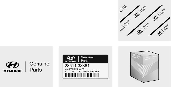
A100A01L-GAT
GUIDE TO HYUNDAI GENUINE PARTS
1.What are Hyundai Genuine Parts?
Hyundai Genuine Parts are the same parts used by Hyundai Motor Company to manufacture vehicles. They are designed and tested for the optimum safety, performance, and reliability to our customers.
2.Why should you use genuine parts?
Hyundai Genuine Parts are engineered and built to meet rigid manufacturing requirements. Using imi-
tation, counterfeit or used salvage parts are not covered under the
Hyundai New Vehicle Limited Warranty or any other Hyundai warranty. In addition, any damage to or failure of Genuine Hyundai Parts caused by the installation or failure of an imitation, counterfeit or used salvage part is not covered by Hyundai Motor Company.
3.How can you tell if you purchasing Hyundai Genuine Parts?
Look for the Hyundai Genuine Parts Logo on the package (see below).
The export specifications are written in English only.
Hyundai Genuine Parts are only sold through authorized Hyundai Dealership and Service Center.
A100A03L
A100A04L

TABLE OF CONTENTS
SECTION
|
BEFORE DRIVING YOUR VEHICLE |
1 |
|
INSTRUMENTS AND CONTROLS |
2 |
|
STARTING AND OPERATING |
3 |
|
IN CASE OF EMERGENCY |
4 |
|
APPEARANCE CARE |
5 |
|
VEHICLE MAINTENANCE REQUIRMENTS |
6 |
|
EMISSION CONTROL SYSTEM |
7 |
|
DO-IT-YOURSELF MAINTENANCE |
8 |
|
VEHICLE SPECIFICATIONS |
9 |
|
INDEX |
10 |
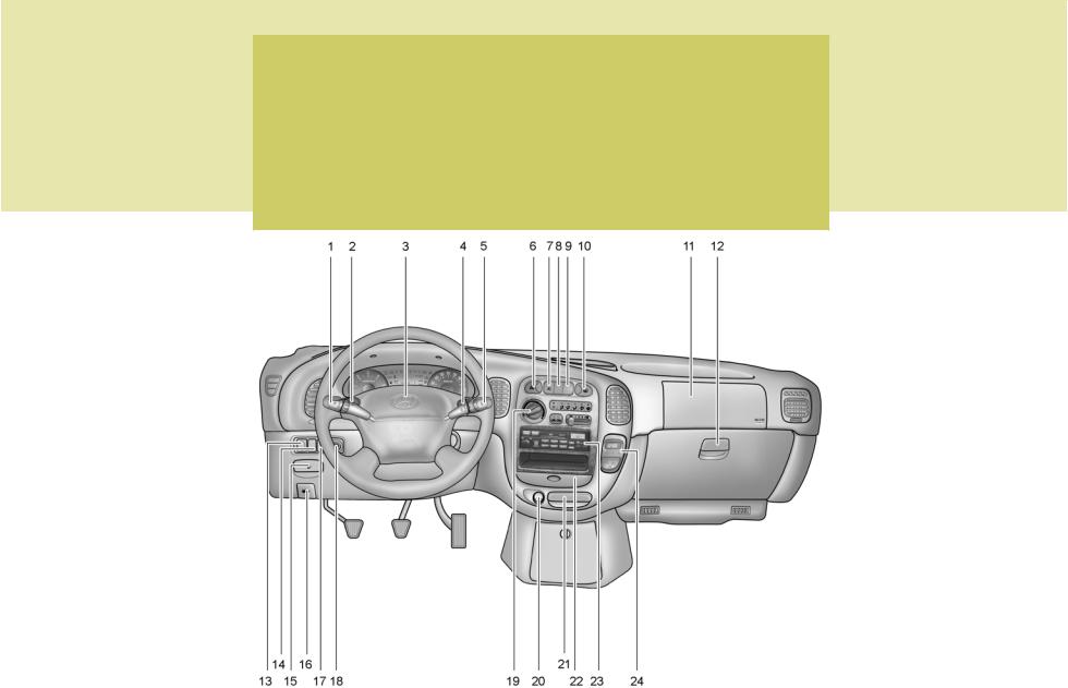
INSTRUMENTS AND CONTROLS (MINIBUS/VAN)
B250A01P-GAT
HSRFL002-1
![]()
|
1. |
Multi-function light switch |
13. Headlight leveling device switch (If installed) |
|
2. |
Seat warmer switch (If installed) |
14. ECT switch (Automatic transmission only) |
|
3. |
Horn/Driver’s side airbag (If installed) |
15. Fuel-filler lid release lever |
|
4. |
Rear heater switch (If installed) |
16. Hood release lever |
|
5. |
Windshield wiper/Washer switch |
17. Panel brightness control knob (Rheostat) (If installed) |
|
6. |
Hazard warning switch |
18. Engine RPM adjustment knob (If installed) |
|
7. |
Front fog light switch (If installed) |
19. Heater/Air conditioner control panel |
|
8. |
4WD Switch (If installed) |
20. Cigarette lighter |
|
9. |
Rear fog light switch (If installed) |
21. Ashtray |
|
10. Rear window defroster switch |
22. Drink holder |
|
|
11. Passenger’s side airbag (If installed) |
23. Audio system (If installed) |
|
|
12. Glove box |
24. Digital clock (If installed) |
!CAUTION:
When installing the container of liquid air refresher inside a vehicle, do not place it near the instrument cluster nor on the crash pad surface. If there is any leakage from the air refresher onto these areas (Instrument cluster, crash pad or air ventilator), it may damage these parts. If the liquid from air refresher does leak onto these areas, wash them with water immediately.
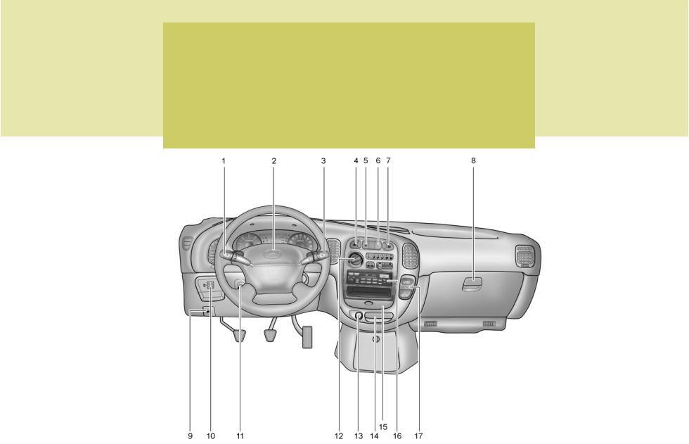
INSTRUMENTS AND CONTROLS (TRUCK)
B250B01P-GAT
C020A02P-2

1.Multi-function light switch
2.Horn/Driver’s side airbag (If installed)
3.Windshield wiper/Washer switch
4.Hazard warning switch
5.Front fog light switch (If installed)
6.Rear fog light switch (If installed)
7.Outside rearview mirror heater switch (If installed)
8.Glove box
9.Hood release lever
10.Headlight leveling device switch (If installed)
11.Engine RPM Adjustment Knob
12.Heater/Air conditioner control panel
13.Cigarette lighter
14.Ashtray
15.Drink holder
16.Audio system (If installed)
17.Digital clock (If installed)
!CAUTION:
When installing the container of liquid air refresher inside a vehicle, do not place it near the instrument cluster nor on the crash pad surface. If there is any leakage from the air refresher onto these areas (Instrument cluster, crash pad or air ventilator), it may damage these parts. If the liquid from air refresher does leak onto these areas, wash them with water immediately.

YOUR VEHICLE AT A GLANCE
B255A01P-GAT
INDICATOR SYMBOLS ON THE INSTRUMENT CLUSTER
SRS (Airbag) Service Reminder Indicator Light (If installed)
ABS Service Reminder Indicator Light (If installed)
O/D OFF Indicator Light (Automatic Transmission Only)
Turn Signal Indicator Lights
High Beam Indicator Light
Low Oil Pressure Warning Light
Parking Brake/Low Brake Fluid Level
Warning Light
Charging System Warning Light
Seat Belt Warning Light (If installed)
Door Ajar Warning Light
Low Fuel Level Warning Light
POWER/HOLD Indicator Light (If installed)
Malfunction Indicator Light (If installed)
4WD HIGH/LOW Indicator Light (If installed)
Immobilizer Warning Light (If installed)
Diesel Pre-heat Indicator Light (Diesel only)
Fuel Filter Warning Light (Diesel only)
* More detailed explanations of these items will be found beginning on page 2-8.

BEFORE DRIVING YOUR VEHICLE
|
Before Driving Your Vehicle Safety Checks |
……………. 1-2 |
|
Running-in Recommendations ………………………………. |
1-2 |
|
Vehicle Identification Number (VIN) ……………………….. |
1-4 |
|
Keys …………………………………………………………………… |
1-6 |
|
Immobilizer System ……………………………………………… |
1-6 |
|
Illuminated Ignition Switch ………………………………….. |
1-11 |
|
Door …………………………………………………………………. |
1-12 |
|
Hold Open Lock System …………………………………….. |
1-13 |
|
Central Door Locks …………………………………………….. |
1-14 |
|
Theft-alarm System ……………………………………………. |
1-15 |
|
Tail Gate/Rear Gate/Side Gate ……………………………. |
1-19 |
|
Hood Release ……………………………………………………. |
1-23 |
|
Remote Fuel-filler Lid Release …………………………….. |
1-24 |
|
Window …………………………………………………………….. |
1-25 |
|
Seats ……………………………………………………………….. |
1-28 |
|
Seat Belts …………………………………………………………. |
1-37 |
|
Child Restraint System ……………………………………….. |
1-42 |
|
Steering Wheel Tilt Lever ……………………………………. |
1-46 |
|
Supplemental Restraint (Airbag) System ………………. |
1-46 |

|
1BEFORE DRIVING YOUR VEHICLE |
||
|
2 |
BEFORE DRIVING YOUR |
RUNNING-IN RECOMMEN- |
|
VEHICLE SAFETY CHECKS |
DATIONS |
|
|
B010A01P-GAT |
B020A01P-GAT |
Be sure you know your vehicle and its equipment and how to use it safely.
B010B01P-GAT
Before entering the vehicle
o Check that windows, mirrors and lights are clean.
oCheck if any tire is low or flat.
oLook for fluid leaks.
oCheck that area is clear if you’re about to back up.
B010C03P-GAT
After entering the vehicle
oLock all doors.
oThe driver and passengers are wearing properly adjusted seat belts.
oThe head restraints are properly adjusted, if so equipped.
oAdjust inside and outside mirrors.
oCheck warning lights for correct operation, with the ignition key in the position «ON».
oCheck all gauges, for normal operation.
!
WARNING: (Diesel only)
To ensure that sufficient vacuum exists within the brake system during cold weather start-up conditions, it is necessary to run the engine at idle after starting the engine.
NOTE:
Fluid levels, such as engine oil, engine coolant, brake fluid, and windshield washer fluid, should be checked daily and/or weekly, or whenever you refuel.
Further details are described in the «CONSUMER INFORMATION» section.
During the running-in period for the first 1,000km(600miles), it is advisable to drive your new vehicle using the following precautions as a guideline to aid long life as well as future economy and performance.
1.Do not race the engine at high speeds.
2.Avoid rapid starting, acceleration, braking and prolonged high-speed running.
3.Keep to the running-in speed limit shown below.
Please note that the legal speed limits displayed must be adhered to.
|
km/h (mph) |
|
|
Drive range |
Running-in speed |
|
1st |
0~25(0~16) |
|
2nd |
20~50(13~31) |
|
3rd |
30~80(19~50) |
|
4th |
40~(25~) |
|
5th |
50~(32~) |
4.Do not exceed loading limits.
5.Refrain from towing a trailer.

BEFORE DRIVING YOUR VEHICLE 1
3
|
B030A01P-GAT |
B040A01P-GAT |
B055A02P-GAT |
BEFORE OPERATION PRECAUTIONS FOR NEW VEHICLE
The performance and life of a vehicle depend largely on how the vehicle is handled when new.
To maintain the parts smoothly and sustain high performance for a long time to come, be sure to observe the following points.
Make sure that your vehicle does not miss the first 5,000 km inspections.
OPERATION IN FOREIGN COUNTRIES
If you are going to drive your Hyundai in another country, be sure to:
o Observe all regulations regarding registration and insurance.
o Determine that acceptable fuel is available.
LOADING YOUR VEHICLE
Never load the luggage and people to exceed GVWR(MLW) and GAWR of your vehicle.
You can find the GVWR(MLW) and GAWR -maximum loading capacitieson the VIN plate.
The GVWR(Gross Vehicle Weight
Rating) or MLW(Maximum Loaded Weight) means total weight of the vehicle, all occupants, fuel and cargo.
And GAWR means the maximum weights that the front and rear axles can endure the weights including vehicle itself weight.
After the first 5,000 km of driving, take your vehicle to your nearest service shop for inspection.
!
WARNING:
Improperly loading your car can seriously affect its steering and braking performance causing a crash in which you may be seriously injured or killed.
NOTE:
Your warranty does not cover parts or components that fail because of overloading.

1BEFORE DRIVING YOUR VEHICLE
|
4 |
VEHICLE IDENTIFICATION |
|
NUMBER (VIN) |
B070A01P-GAT
MAINTENANCE
It is necessary to maintain your vehicle in top operating condition in order to enjoy safe and pleasant driving.
Some maintenance items can be done by the owner (Consumer information), while others should be done only by an authorized dealer (periodic inspection and maintenance).
For the maintenance items to be done by the owner, prepare the appropriate materials and tools and follow the procedures given in the «Consumer information» section of this manual.
However, the periodic inspection and maintenance should not be attempted by the owner, but should be done by an authorized HYUNDAI dealer.
Correct performance of the periodic inspection and maintenance items requires specialized knowledge and equipment.
Having these items performed by an authorized HYUNDAI dealer with the latest technology and equipment will ensure that your vehicle is maintained for optimum performance, economy, and safety.
In addition, having all periodic inspection and maintenance done by an authorized HYUNDAI dealer is a prerequisite for validity of the warranty on your vehicle in the event of a claim.
Refer to the separate «Service Booklet» for the periodic inspection and maintenance items and intervals.
B080A01P-GAT
INSTALLATION OF ACCESSORIES
Consult an authorized HYUNDAI dealer when installing accessories.
oInstallation of some accessories may be restricted by regulations.
oImproper installation of electrical parts could cause fire.
oNever use tires or wheels which do not meet specifications.
For wheel and tire sizes, refer to the «CONSUMER INFORMATION» section of this manual.
B050A02P-GAT
HSRFL049
The vehicle identification plate is attached on the fender inner panel as shown in the illustration. The vehicle identification number (VIN) is the number used in registering your car and in all legal matters pertaining to its ownership, etc.

BEFORE DRIVING YOUR VEHICLE 1
5
Minibus/Van
HSRFL051
Truck
HSR008
The vehicle identification number is stamped as shown in the illustration. Please use this number when ordering replacement parts.
B060A01P-GAT
ENGINE NUMBER
Diesel Engine
2.6 N/A
B060A01P
2.5 4D56 TCI
B060B01P
2.5 CRDi TCI
B060C01P
Gasoline Engine
2.4 DOHC
B060D01P
The engine number is stamped on the engine cylinder block as shown in the illustration.
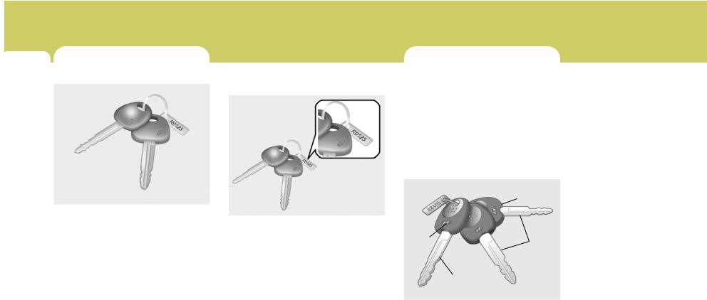
|
1BEFORE DRIVING YOUR VEHICLE |
|||
|
6 |
KEYS |
IMMOBILIZER SYSTEM |
|
|
B030A01A-AAT |
B030B01A-AAT |
B880A01P-GAT |
|
|
Record Your Key Number |
(Minibus/Van) (If installed) |
The immobilizer system is an anti-theft device, designed to prevent and deter automobile theft.
B030A01E
For greater convenience, the same key operates all the locks in your Hyundai. However, because the doors can be locked without a key, carrying a spare key is recommended in case you accidentally lock one key inside the car.
B030B01E
A code number is stamped on the number plate that came with the keys to your Hyundai. This key number plate should not be left with the keys but kept in a safe place, not in the vehicle. The key number should also be recorded in a place where it can be found in an emergency.
If you need additional keys, or if you should lose your keys, your authorized
Hyundai dealer can make new keys if you can supply the key number.
B880B02P-GAT
Keys
Without Theft-alarm system
|
Black |
||
|
Light |
Master |
|
|
Purple |
||
|
key |
||
ID key
B880B01HP-1
![]()
BEFORE DRIVING YOUR VEHICLE 1
7
With Theft-alarm system
ID key
Master key
B880B01P-1
All of the locks fitted to the vehicle are operated by the same key. However, since it is possible to lock the doors without the use of the key, care should be exercised to ensure that the key does not become locked inside the vehicle by mistake.
For greater convenience, your Hyundai has two types of keys as shown in the illustration.
ID key
This key must be used first to register a unique ID code in the ICU. This ID code is then recorded onto the master keys. Both sides of the key has a Hyundai logo.
Master key
This key is for general use. It will open all locks on your vehicle.
One side of the key has the Hyundai logo and the other side has the «M» symbol.
If your vehicle is equipped with Theftalarm system, the master keys with the function of transmitter will be provided. (E.C only)
NOTE:
If you make your own duplicate key, you will not be able to cancel the system or start the engine.
!CAUTION:
Don’t lose your ID key or forget the password. Always keep your ID key in a place where you remember and record your password. If you don’t have both the password and ID key, consult your authorized Hyundai dealer.
B880C01A-GAT
Key Numbers
Without Theft-alarm system
B880C01HP-1
With Theft-alarm system
B880C01P-1
The vehicle key number is recorded on a metal tag attached to the keys when the vehicle is first delivered to you.

1BEFORE DRIVING YOUR VEHICLE
8
The key number should be recorded and kept in a safe place in case the need to order further keys arise. New keys are available from any Hyundai dealer by quoting the relevant key number.
In the interest of security, the metal tag attached to the keys which bears the key number should be removed from the key ring after delivery. In addition, key numbers cannot be provided by Hyundai for security reasons.
If you need additional keys or if you should lose your keys, your authorized Hyundai dealer can make new keys if you can supply the key number and ID key.
B880D02E-GAT
Limp home procedures
B880D02P
In case the immobilizer system is out of order, you cannot start the engine without the limp home procedures with ignition key.
The following procedure is how to start the engine with the function of the limp home. (0, 1, 2, 3 as a sample password).
NOTE:
You can get the limp home password when the vehicle is first delivered to you. If you do not have the password, consult your authorized Hyundai dealer.
1.To set the password, you may turn the ignition key «ON» and then turn it «OFF» according to the digit numbers. For example, turn the ignition key once for digit number «1», and twice for «2», and so on. However, for the digit number «0», you must turn the ignition key for 10 times.
2.Wait for 3~10 seconds.
3.You may set the remaining number of digits by following the same procedures 1 and 2.
4.If all of four digits have been tried successfully, from this time, you have to start your engine within 30 seconds. If you start your engine after 30 seconds, your engine will not start.
NOTE:
If the engine dies while driving after limp home procedure, you can start your engine within 8 seconds in condition of ignition OFF without limp home procedure again.
After doing the limp home procedure, you have to consult with your authorized Hyundai dealer as soon as possible.
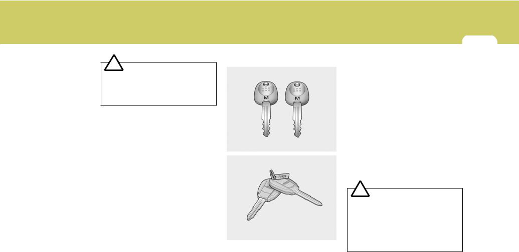
BEFORE DRIVING YOUR VEHICLE 1
9
!CAUTION:
If you cannot start your engine in spite of limp home procedure, have your vehicle towed by an authorized Hyundai dealer.
B885B01P-GAT
Keys
Without Theft-alarm system
B885A01O-GAT
IMMOBILIZER SYSTEM
|
(Truck) (If Installed) |
B880B01O-1 |
|
|
The immobilizer system is an anti-theft |
With Theft-alarm system |
|
|
device, designed to deter automobile |
||
|
theft. |
B880B02P-1
All of the locks fitted to the vehicle are operated by the same key. However, since it is possible to lock the doors without the use of the key, care should be exercised to ensure that the key does not become locked inside the vehicle by mistake.
If your vehicle is equipped with Theftalarm system, the master keys with the function of transmitter will be provided. (E.C only)
NOTE:
If you make your own duplicate key, you will not be able to cancel the system or start the engine.
!CAUTION:
o The password should be recorded and kept in a safe place in case the need to order further keys arises.
oIf you forget the password, consult your authorized Hyundai dealer.
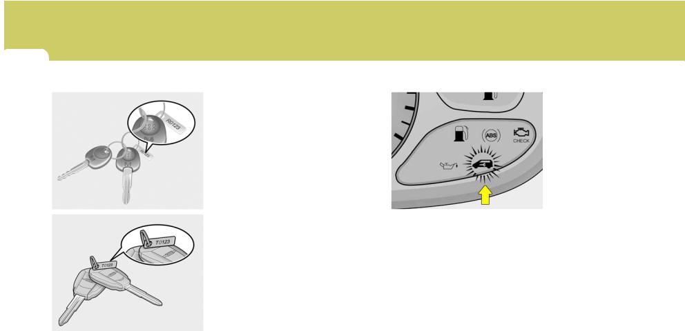
1BEFORE DRIVING YOUR VEHICLE
10
B885C02A-GAT
Key Numbers
Without Theft-alarm system
B885C01B-1
With Theft-alarm system
B885C02P-1
The vehicle key number is recorded upon a metal tag attached to the keys when the vehicle is first delivered to you.
The key number should be recorded and kept in a safe place in case the need to order further keys arises. New keys are available from any Hyundai dealer by quoting the relevant key number.
In the interest of security, the metal tag attached to the keys which bears the key number should be removed from the key ring after you receive your new vehicle. In addition, key numbers cannot be provided by Hyundai for security reasons.
If you need additional keys or if you should lose your keys, your authorized
Hyundai dealer can make new keys.
B880D02A-GAT
Limp home procedures
B880D02P-1
In case the immobilizer warning indicator blinks for five seconds when the ignition key is turned to «ON» position, this indicates that the immobilizer system is out of order. And you cannot start the engine without the limp home procedures with ignition key.
The following procedure is how to start the engine with the function of the limp home. (0, 1, 2, 3 as a sample password).

BEFORE DRIVING YOUR VEHICLE 1
|
ILLUMINATED IGNITION |
11 |
|||
|
NOTE: |
NOTE: |
SWITCH |
||
|
B120A02P-GAT |
||||
|
You can get the limp home pass- |
If the engine dies while driving after |
(If installed) |
||
|
word when the vehicle is first deliv- |
limp home procedure, you can start |
|||
|
ered to you. If you do not have the |
your engine within 8 seconds with- |
|||
|
password, consult your authorized |
out limp home procedure again. |
|||
|
Hyundai dealer. |
||||
|
5. If the immobilizer indicator blinks for |
||||
|
1. To set the password you may turn |
five seconds, you have to try the |
|||
|
the ignition key «ON» and then turn |
limp home procedure again from |
|||
|
it «OFF» according to the digit num- |
the beginning. |
|||
|
bers, then the immobilizer indicator |
||||
|
will blink along with the operation of |
After doing the limp home procedure, |
|||
|
the ignition key. For example, turn |
you have to consult with your autho- |
B120A02P |
||
|
the ignition key once for digit num- |
rized Hyundai dealer as soon as pos- |
|||
|
Whenever a front door is opened, the |
||||
|
ber «1», and twice for «2», and so on. |
sible. |
|||
|
ignition switch will illuminate for your |
||||
|
However, for the digit number «0», |
||||
|
convenience. |
||||
|
you must turn the ignition key for 10 |
||||
|
The light will go off when the ignition |
||||
|
times. |
! |
CAUTION: |
||
|
switch is turned on or 10 seconds after |
||||
|
2. Wait for 3~10 seconds. |
o If you fail to try the limp home |
|||
|
closing the door. |
||||
|
3. You may set the remaining number |
||||
|
procedure with the sequence of |
||||
|
of digits by following the same pro- |
||||
|
three times, you have to wait for |
||||
|
cedures 1 and 2. |
||||
|
about one hour to do the limp |
||||
|
4. If all of four digits have been tried |
||||
|
home procedure again. |
||||
|
successfully, turn the ignition key |
||||
|
o If you cannot start your engine in |
||||
|
«ON» and check that the immobi- |
||||
|
spite of limp home procedure, |
||||
|
lizer indicator illuminates. From this |
||||
|
have your vehicle towed by an |
||||
|
time, you have to start your engine |
||||
|
authorized Hyundai dealer. |
||||
|
within 30 seconds. If you start your |
||||
|
engine after 30 seconds, your en- |
||||
|
gine will not start. |
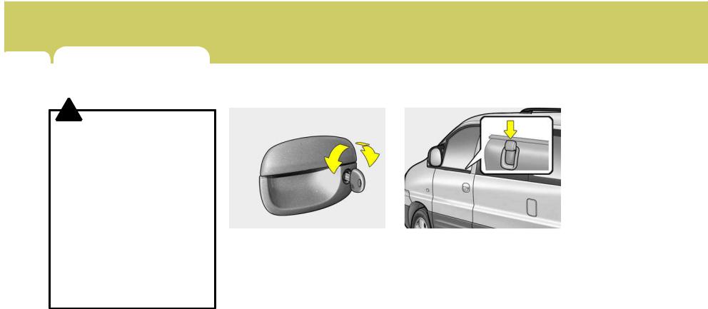
1BEFORE DRIVING YOUR VEHICLE
12 DOOR
|
B040A01A-AAT |
B040B01A-AAT |
B130B01P-GAT |
DOOR LOCKS
!
WARNING:
oUnlocked doors can be dangerous. Before you drive away (especially if there are children in the car), be sure that all the doors are securely closed and locked so that the doors cannot be inadvertently opened from the inside. This helps assure that doors will not be opened accidentally.
Also, when combined with the proper use of seat belts, locking the doors helps keep occupants from being ejected from the car in case of an accident.
oBefore opening the door, always look for and avoid oncoming traffic.
Locking and Unlocking Front
Doors With a Key
UNLOCK
LOCK
B040B01P
oThe door can be locked or unlocked with a key.
oLock the door by turning the key toward the front of the vehicle and unlock it by turning the key toward the rear.
To lock the front doors without a key
B130B01P
Set the inside lock button to the locked position, and close the door.
Be careful not to lock the doors while the key is inside the vehicle.
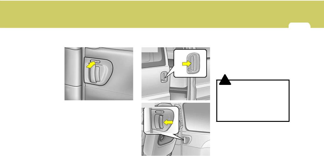
BEFORE DRIVING YOUR VEHICLE 1
13
B130C01P-GAT
To lock the slide door without a key
B130C01P
Set the inside lock button to the locked position, and close the door.
B140A01P-GAT
HOLD OPEN LOCK SYSTEM (Minibus/Van)
Outside
B140B01P
Inside
To prevent accidental closing of sliding door in slope, the sliding door should be always fully opened.
When the sliding door is open fully, it is locked in position.
To close the sliding door, pressing the hold open lever, pull the door handle towards the front of the vehicle.
!
WARNING:
o Do not open the sliding doors while the vehicle is moving.
oIf the sliding doors should not be fully closed and locked, this could result in serious injury or death in case of an accident or sudden stop.
B140A01P
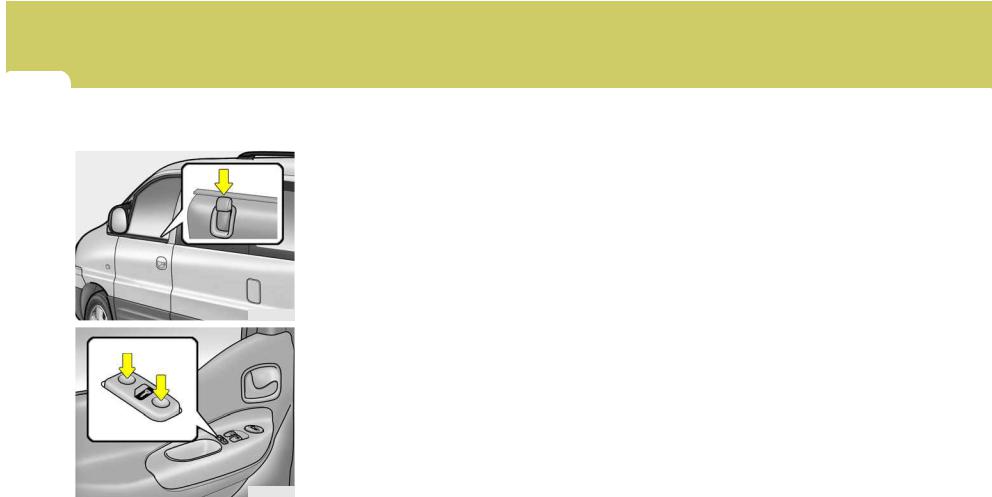
1BEFORE DRIVING YOUR VEHICLE
14
B150A01P-GAT
CENTRAL DOOR LOCKS (Minibus/Van) (If installed)
B130B01P
Unlock
Lock
The central door locking system is located on the driver’s door lock button. It is operated by depressing the door lock button. If the rear door is open when the button is depressed, the door will remain locked when closed. If the front door is open when the button is depressed, the door will lock when closed.
NOTE:
When the front door lock button is depressed, the front and slide doors will lock. When the front door lock button is pulled up, the front and slide doors will unlock.
The operation of the tailgate door locking is identical to the central door locking system.
B150B01P-GAT
(Truck) (If installed)
The central door locking system is located on the driver’s door lock button. It is operated by depressing the door lock button. If the front door is open when the button is depressed, the door will lock when closed.
NOTE:
When the front door lock button is depressed, the front doors will lock. When the front door lock button is pulled up, the front doors will unlock.
B130B02P

BEFORE DRIVING YOUR VEHICLE 1
B160A02P-GAT
«CHILD-PROTECTION» SLIDE DOOR(Minibus/Van)
B160B01P-GAT
CARRYING CHILDREN
oIf a child is left in the vehicle alone, always be sure to turn off the ignition and remove the key.
oIf a child is seated alone in the second seat, use the child-protec- tion system.
B070A01P-GAT
(Minibus) (If installed)
This system is designed to provide protection from unauthorized entry into the car. This system is operated in three stages: the first is the «Armed» stage, the second is the «Alarm» stage, and the third is the «Disarmed» stage. If triggered, the system provides an audible alarm with blinking of the turn signal light.
HSRFL161
When the slide door is closed with the
«child-protection» lever in the »  » position, it cannot be opened by using the inner handle. Use the outer handle to open the door.
If adults are to sit in the second seat, release the child protection lock. When this is done, the lever will be in the « » position.
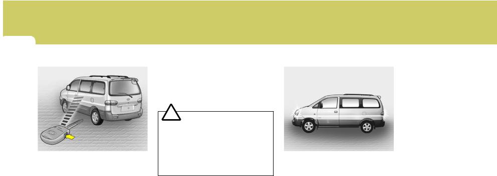
1BEFORE DRIVING YOUR VEHICLE
16
B070B01O-AAT
Armed Stage
B070B02P
Park the car and stop the engine. Arm the system as described below.
(1)Remove the ignition key from the ignition switch.
(2)Make sure that the engine hood and tail gate are locked.
(3)Lock the doors using the transmitter of the keyless entry system.
After completion of the steps above, the turn signal light will blink once to indicate that the system is armed.
NOTE:
o If any door, tail gate or engine hood remains open, the system will not be armed.
oIf this happens, rearm the system as described above.
!CAUTION:
Do not arm the system until all passengers have left the car. If the system is armed while a passenger(s) remains in the car, the alarm may be activated when the remaining passenger(s) leaves the car.
B070C01FC-GAT
Alarm Stage
B070B03P
The alarm will be activated if any of the following occurs while the car is parked and the system is armed.
(1)A front or rear door is opened without using the transmitter.
(2)The tail gate is opened without using the transmitter.
(3)The engine hood is opened.
![]()
BEFORE DRIVING YOUR VEHICLE 1
17
The alarming horn will sound and the turn signal light will blink continuously for 27 seconds (E.C only/ Except E.C 3 times). To turn off the system, unlock the door or tail gate with the transmitter.
!CAUTION:
Avoid trying to start the engine while the system is armed.
B070D02P-AAT
Disarmed Stage
The system will be disarmed when the driver’s or passenger’s door is unlocked by depressing the «UNLOCK» button on the transmitter.
After completion of the step above, the turn signal light will blink twice to indicate that the system is disarmed.
NOTE:
oOnce the system has been disarmed, it can not be rearmed except by repeating the arming procedures.
oWhen the system is disarmed with the interior light switched to «DR», the interior light will illuminate for 30 seconds.
!CAUTION:
Only the transmitter can disarm the armed stage. If the transmitter does not disarm the system, it is necessary to take the following steps;
1.Unlock the door with the key, which will cause, the alarm to be activated.
2.Insert the key in the ignition key cylinder and turn the ignition key to «ON» position.
3.Wait for 30 seconds.
After completing the steps above, the system will be disarmed.

1BEFORE DRIVING YOUR VEHICLE
18
B070F01A-GAT
Keyless Entry System (If installed)
Locking doors
1.Close all doors.
2.Push the «LOCK» button on the transmitter.
3.At the same time all doors lock, the turn signal lamp will blink once to indicate that the system is armed.
Unlocking doors
1.Push the «UNLOCK» button on the transmitter.
2.At the same time all doors unlock, the turn signal lamp will blink twice to indicate that the system is disarmed.
B070E01TB-AAT
Replacing the battery
When the transmitter’s battery begins to get weak, it may take several pushes on the button to lock or unlock the doors, and the LED will not light. Replace the battery as soon as possible.
Battery type : CR1220 (Minibus/Van)
CR2032 (Truck)
Replacement instructions: (Minibus/Van)
HTB053
1.Remove the screw with a phillips screwdriver.
2.Carefully separate the case with a flat-head screwdriver as shown in the illustration.
HTB054
3.Remove four screws at the back side of the built-in circuit.
HTB055

BEFORE DRIVING YOUR VEHICLE 1
4.Remove the old battery from the case and note the polarity. Make sure the polarity of the new battery is the same (+side facing up), then insert it in the transmitter.
(Truck)
B190A01P-GAT
LIFT TYPE
Operation from outside the vehicle (Minibus/Van)
LOCK UNLOCK
B070E02P-1
2. Remove the old battery from the case and note the polarity. Make sure the polarity of the new battery is the same(+side facing down), then insert it in the transmitter.
B070E01P-1
1.Separate the case with a phillips screwdriver.
B190A01P
Pull the outside handle toward you to open the tail gate.

1BEFORE DRIVING YOUR VEHICLE
20
|
B190B02P-GAT |
When the tail gate is locked |
|
|
Operation from inside the |
||
|
vehicle (Van) |
||
|
outside |
||
|
handle |
||
|
lock rod |
rod |
|
B190B03P
2.Insert the finger into the tail gate opening hole, and press down the
|
B190B01P |
outside handle rod to open the tail |
|
gate. |
B190B04P
1.Pull the tail gate open cover.
2.Insert the finger into the tail gate opening hole, and pull upward the lock rod (thin rod), and press down the outside handle rod (thick rod) to open the tailgate.
B190B02P
1.When the tail gate is unlocked, pull the tail gate open cover.

BEFORE DRIVING YOUR VEHICLE 1
B190C01P-GAT
TWIN SWING DOOR TYPE (Van)
Outside
Unlock Lock
B190C01P-1
To open from outside, lift the door handle up.
Inside
B190E01P
When opening the left door, pull the lever toward your side.
B191A01P-GAT
To open the rear gate (Truck)
B191A01P
1.Push the rear gate handle inside and pull it toward you.
B190D01P
To open from inside, pull the inside door handle.
B191A02P
2. Lower the rear gate slowly.

1BEFORE DRIVING YOUR VEHICLE
B191A03P
NOTE:
When you step on the cargo deck, use the foothold.
!
WARNING:
When the rear combination lamps are hidden, other road users should be warned by means of warning triangle or other devices.
To close the rear gate
Lift the rear gate up and lock the rear gate handle in place.
B191B01P-GAT
To open the side gate (Truck)
Support bar
B191B01P
1.With the rear gate opened, pull up the knob to release the support bar down.
B191B02P
2.Remove the side gate handle from the hook after pulling it up.
3.Lower the side gates slowly.

BEFORE DRIVING YOUR VEHICLE 1
To close the side gate
B191B03P
1.Lift the side gate up and lock the side gate handle in place.
B191B04P
2.Push the knob down to lock the side gates.
B570A01F-GAT
B570A02P
1.Pull the release knob to unlatch the hood.
Minibus/Van
B570A03P
Truck
B570B03P
2.Press the secondary latch lever up side and lift the hood.
3.Hold the hood open with the support rod.
Before closing the hood, return the support rod to its clip to prevent it from rattling. Lower the hood until it is about 30 cm (1 ft.) above the closed position and let it drop. Make sure that it locks into place.
!CAUTION:
Make sure that the support rod has been released prior to closing the hood.

1BEFORE DRIVING YOUR VEHICLE
|
24 |
REMOTE FUEL-FILLER |
|||
|
LID RELEASE |
NOTE: |
|||
|
B200A01P-GAT |
||||
|
! |
WARNING: |
(Minibus/Van) |
If the fuel-filler lid will not open |
|
|
because ice has formed around it, |
||||
|
o Always double check to be sure |
tap lightly or push on the lid to |
|||
|
that the hood is firmly latched |
break the ice and release the lid. Do |
|||
|
before driving away. If it is not |
not pry on the lid. If necessary, |
|||
|
latched, the hood could fly open |
spray around the lid with an ap- |
|||
|
while the vehicle is being driven, |
proved de-icer fluid (do not use |
|||
|
causing a total loss of visibility, |
radiator anti-freeze) or move the |
|||
|
which might result in an acci- |
vehicle to a warm place and allow |
|||
|
dent. |
the ice to melt. |
|||
|
o The support rod must be inserted |
||||
|
completely into the hole provided |
B200A02P |
|||
|
in the hood whenever you in- |
||||
|
spect the engine compartment. |
B200B01P-GAT |
|||
|
This will prevent the hood from |
Refueling (Minibus/Van) |
|||
|
falling and possibly injuring you. |
Use the fuel best suited to the engine |
|||
|
o Do not move the vehicle with the |
||||
|
of your vehicle. |
||||
|
hood in the raised position, as |
||||
|
Excessively low cetane fuel may cause |
||||
|
vision is obstructed and the hood |
||||
|
ignition pinging and consequently dam- |
||||
|
could fall or be damaged. |
||||
|
age engine. |
||||
|
Please find the cetane number most |
||||
|
appropriate to your engine. |
||||
|
GT10230A |
||||
|
The fuel-filler lid may be opened from |
||||
|
inside the vehicle by pulling up on the |
||||
|
fuel-filler lid opener located on the dash- |
||||
|
board at the left side of the car. |

BEFORE DRIVING YOUR VEHICLE 1
B200C01H-GAT
Fuel tank cap key (Truck)
GT10221A
The fuel tank cap can be opened whenever you fuel-up. You lock the fuel tank cap by turning the key toward the front of the vehicle and unlock it by turning it toward the rear.
The fuel tank cap is located at the left side of the vehicle body.
!WARNING:
Fuel vapors are dangerous. Before refueling, always stop the engine and never allow sparks or open flames near the filler area. If you need to replace the filler cap, use a genuine Hyundai replacement part. If you open the fuel filler cap during high ambient temperatures, a slight «pressure sound» may be heard. This is normal and not a cause for concern. Whenever you open the fuel filler cap, turn it slowly.
B230A01P-GAT
FRONT DOOR WINDOW GLASS Manual type
CLOSE
OPEN
GT10260A
Turn the window regulator handle to raise or lower the window.
!
WARNING:
When opening or closing the windows, make sure your passenger’s arms and hands are safely out of the way.

1BEFORE DRIVING YOUR VEHICLE
26
B250A01P-GAT
POWER WINDOW (If installed)
Close
Open
HSRFL250
Power window operates when the ignition key is in the «ON» position.
The main switches are located on the driver’s armrest and control the front windows on the respective sides of the vehicle.
The windows may be opened by depressing the appropriate window switch.
To stop at the desired opening, release the switch. The window may be closed by pulling the front portion of the switch.
Auto-Down window (Driver’s Side)
The Auto-Down window is moved to its fully open position by push on the switch, and push in on the switch again to stop at the desire position.
!CAUTION:
Never try to operate the main switch and sub switch in opposing directions at the same time. If this is done, the window will stop and cannot be opened or closed.
!WARNING:
o Be careful that head or hands and body are not trapped by a closing window.
oIf passengers remain in the car when you leave, especially if a child remains alone, always remove the ignition key for their safety.
B210A01P-GAT
REAR SIDE, QUARTER WINDOW Hinged window (Minibus)
B210A01P
To open
Pull the lever all the way in the direction of the arrow. Press the center of the lever to hold it securely in place.
To close
Pull the center of the lever toward you.
When the window is closed, lock the lever securely.
![]()
BEFORE DRIVING YOUR VEHICLE 1
27
B220A01P-GAT
Sliding window glass (Van)
OPEN
CLOSE
GT10250A
To open
Slide the window glass while pressing the lock knob.
To close
Slide the window glass all the way and it will automatically lock.

1BEFORE DRIVING YOUR VEHICLE
28 SEATS
For 12 passengers
4
5
5
1. FRONT SEAT (See page 1-29)
2. SECOND SEAT (See page 1-31)
3. THIRD SEAT (See page 1-32)
4. FOURTH SEAT (See page 1-33)
HSRFL859
5. AUXILIARY SEAT (See page 1-33)

BEFORE DRIVING YOUR VEHICLE 1
29
|
B080A01A-AAT |
B080B02FC-AAT |
ADJUSTABLE FRONT SEATS
!
WARNING:
Never attempt to adjust the seat while the vehicle is moving. This could result in loss of control, and an accident causing death, serious injury, or property damage.
Adjusting Seat Forward and
Rearward
HSRFL080
To move the seat toward the front or rear, pull the lock release lever upward. This will release the seat on its track so you can move it forward or rearward to the desired position. When you find the position you want, release the lever and slide the seat forward or rearward on its track until it locks into the desired position and cannot be moved further.
!WARNING:
To ensure the seat is locked securely, attempt to move the seat forward or rearward without using the lock release lever.
B080C01A-AAT
Adjusting Seatback Angle
HSRFL081
To recline the seatback, lean forward to take your weight off it, then pull up on the recliner control lever at the outside edge of the seat. Now lean back until the desired seatback angle is achieved. To lock the seatback into position, release the recliner control lever.

1BEFORE DRIVING YOUR VEHICLE
30
!
WARNING:
To minimize risk of personal injury in the event of a collision or a sudden stop, both the driver and passenger seatbacks should always be in an upright position while the vehicle is in motion. The protection provided by the seat belts and airbags may be reduced significantly when the seatbacks are reclined. There is greater risk that the driver and passenger will slide under the belt resulting in serious injury if a crash occurs when the seatbacks are reclined. The seat belt cannot provide full protection to an occupant if the seat back is reclined.
B260A01P-GAT
Lumbar Support Control (Driver’s Seat Only) (If installed)
Minibus/Van
2
1
HSRFL082
Truck
2
1
B260B01P
To increase the amount of lumbar support, turn the handle forward. To decrease it turn the handle toward the rear.
1.Maximum support
2.Minimum support
B080F01S-AAT
Seat Cushion Height Adjustment (Driver’s Seat Only) (If installed)
HSRFL083
To raise or lower the front part of the seat cushion, turn the front knob forward or rearward. To raise or lower the rear part of the seat cushion, turn the rear knob forward or rearward.

BEFORE DRIVING YOUR VEHICLE 1
31
|
B290A01P-GAT |
B290B02P-GAT |
B290C03P-GAT |
SECOND AND THIRD SEATS
Adjusting Seat Forward and
Rearward (Minibus)
HSRFL084
Pull the lever up and hold it while you slide the seat forward or backward to desired position. Release the lever to lock the seat in position.
To rotate (Second Seat Only)
5
3
HSRFL085
1.Position the driver’s seat at the forefront. And then position the third seat at the end of rearward.
2.Pull the reclining lever and fold the seatback of the front seat.
3.Fold the auxiliary seat. (See page 1-33)
4.Pull the lever (a) and slide the seat at the end of rearward.
5.Pull the lever (b) and incline the seatback forward.
6.Rotate the seat clockwise.
7.After rotating the seat 90° or 180°, it can be fixed.
8.Adjust the seatback or seat the desired position.
9.Reverse the above procedure to return the seat to the original position.
Type 2
B290C01P
Pull the lever and rotate the seat clockwise.
!
WARNING:
o Never rotate the seat while the vehicle is in motion.
oWhen the seat is rotated, be sure that the seat is securely locked in position.
oWhile driving, ensure the seat is locked facing forward.
If the seat is not facing forward, this may result in serious injury in the event of a sudden stop.

1BEFORE DRIVING YOUR VEHICLE
32
B310A02P-GAT
THIRD SEATS Folding the third seat (Minibus) (If installed)
B310A01P
By folding the third seat, larger articles can be stowed in the vehicle.
1.Remove the headrest and tilt the seatback fully backward.
(a)
B310A02P
2.Pull the strap (a) for raising and fold the seat sideways.
B310A04P
3.Hook the securing band to the assist handle to secure the seat, and fold the legs of the seat.
B310A05P
4.Fix the headrest at the upper part of the seat leg.
5.Reverse the above procedure when returning the seat to the normal position.
!CAUTION:
To return the seat to the normal position, extend the leg of the seat, remove the securing band, and slowly lower the seat.
!
WARNING:
Be careful not to let the seat fall as the seat may catch your hand or foot.

BEFORE DRIVING YOUR VEHICLE 1
33
B320A02P-GAT
FOURTH SEAT Folding the fourth seat (Minibus) (If installed)
(a)
B320A01P
The seatback can be folded down as shown to provide a large cargo space.
1.Push the lever (a) and fold the seatback forward.
(b)
B320A02P
2.Pull the lever (b) and lift the seat cushion until it is fixed.
(c)
B320A03P
3.To make the seat to the original state, release the lock with pushing the lever (c) and after locking the seat at the floor, push the lever (a) and make the seatback erect.
B340A02P-GAT
AUXILIARY SEAT (If installed) To fold the auxiliary seat
HSRFL086
1.Pull the release knob and fold the seatback forward.
HSRFL087
2. Fold up the seat.

1BEFORE DRIVING YOUR VEHICLE
34
NOTE:
To recline the auxiliary seatback rearward, pull the lever and recline the seatback rearward to the locking position.
!CAUTION:
Avoid full flat condition while driving.
B350A02P-GAT
MAKING A FLAT SEAT (If installed)
2.Position the second seat at the forefront and then position the third seat at the end of rearward (For 12 passengers).
|
! |
HA1FL2010 |
|||
|
WARNING: |
1. Remove the headrests. |
HSRFL088 |
||
|
Be careful not to be caught by hand |
||||
|
3. Recline the seatback all the way |
||||
|
or foot under the seat while fixing |
||||
|
backward to make a flat seat. |
||||
|
the auxiliary seat at the suitable |
||||
|
4. One large flat seat achieved. |
||||
|
position. |
||||
HSRFL084

BEFORE DRIVING YOUR VEHICLE 1
35
|
B080D02A-AAT |
B081D01P-GAT |
!CAUTION:
oTo make a flat seat, stop the vehicle in a safe place.
oDo not walk around on top of the seats after they have been laid flat. To avoid loosing your footing, step on the center of the seats and walk slowly.
oTo ensure the seats are locked securely, attempt to move them back and forth.
oDo not jump on, or impact the seatbacks heavily.
oNever drive with the luggage or passengers on the flat seat. This is highly dangerous if heavy braking is required.
oTo raise the seatback, sit on the seat and put a hand on the seatback and raise slowly. Never have a child do this operation, or an unexpected accident may be caused.
HEADREST Adjustable Headrests (If installed)
Lock knob
HSRFL330
Headrests are designed to help reduce the risk of neck injuries.
To raise the headrest, pull it up. To lower it, push it down while pressing the lock knob.
Tilting Forward and Rearward (If installed)
HA1FL2011
The headrest may be tilted forward to each different position by pulling the headrest forward. To adjust the headrest rearward, pull it fully forward to the farthest position and release it. Adjust the headrest so that it properly supports the head and neck.

1BEFORE DRIVING YOUR VEHICLE
36
|
B330B01P-GAT |
B270A01P-GAT |
!
WARNING:
o For maximum effectiveness in case of an accident, the headrest should be adjusted so the top of the headrest is at the same height as the top of the occupant’s ears. The use of a cushion that holds the body away from the seatback is not recommended.
oDo not operate the vehicle with the headrests removed as severe injury to an occupant may occur in the event of an accident. Headrests may provide protection against severe neck injuries when properly adjusted.
Removal of the headrest
To remove the headrest, pull it out while pressing the lock knob in the direction of the arrow.
When installing the headrest, first check to be sure that it is facing in the correct direction, and then insert it into the seatback and press downward until it locks in place.
Check to be sure that the lock knob is in the correct position, as shown in the figure, and then try to pull the headrest up to be sure it doesn’t come out.
!
WARNING:
It is dangerous to drive without installing the head restraints.
SEAT WARMER
(Driver’s seat only) (Minibus) (If installed)
B270A01P
The seat warmer is provided to warm the front seats during cold weather. With the ignition key in the «ON» position, push the switch to warm the driver’s seat.
During mild weather or under conditions where the operation of the seat warmer is not needed, keep the switch in the «OFF» position.
Руководство на английском языке по кузовному ремонту автомобиля Hyundai H-1 1998 года выпуска.
- Автор: —
- Издательство: Hyundai Motor Company
- Год издания: 1997
- Страниц: 137
- Формат: PDF
- Размер: 3,2 Mb
Руководство на английском языке по техническому обслуживанию и ремонту автомобиля Hyundai H-1 2001 года выпуска.
- Автор: —
- Издательство: Hyundai Motor Company
- Год издания: 2001
- Страниц: —
- Формат: PDF
- Размер: 99,5 Mb
Руководство по техническому обслуживанию и ремонту + каталог расходных запчастей автомобилей Hyundai Starex и Hyundai H-1 1998-2007 годов выпуска с дизельными двигателями объемом 2,5/2,6 л.
- Автор: —
- Издательство: Легион-Автодата
- Год издания: —
- Страниц: 428
- Формат: —
- Размер: —
Руководство по техническому обслуживанию и ремонту + каталог расходных запчастей автомобилей Hyundai Grand Starex и Hyundai H-1 с 2007 года выпуска с дизельными двигателями объемом 2,5 л.
- Автор: —
- Издательство: Легион-Автодата
- Год издания: —
- Страниц: 452
- Формат: —
- Размер: —

Руководство по эксплуатации и ремонту автомобилей Hyundai H-1, Hyundai H200, Hyundai Starex и Hyundai Satellite с 2000 года выпуска с бензиновыми и дизельными двигателями.
- Автор: —
- Издательство: Монолит
- Год издания: 2007
- Страниц: 440
- Формат: —
- Размер: —

Руководство по эксплуатации и ремонту автомобилей Hyundai Grand Starex и Hyundai H-1 с 2007 года выпуска с бензиновыми и дизельными двигателями.
- Автор: —
- Издательство: Монолит
- Год издания: —
- Страниц: 432
- Формат: —
- Размер: —
Руководство по эксплуатации и техническому обслуживанию автомобиля Hyundai H-1 2007-2009 годов выпуска.
- Автор: —
- Издательство: Hyundai Motor Company
- Год издания: 2007/2009
- Страниц: 368/381
- Формат: PDF
- Размер: 17,6 Mb

Руководство по эксплуатации автомобиля Hyundai H-1 2002 года выпуска.
- Автор: —
- Издательство: Hyundai Motor Company
- Год издания: 2002
- Страниц: 169
- Формат: PDF
- Размер: 3,2 Mb
