E-MU 1212M PCI
Срок обслуживания истек
Выбранное изделие относится к категории изделий с истекшим сроком обслуживания.
Для таких изделий техническая поддержка ограничивается предоставлением в интерактивном режиме материалов, размещенных на веб-узле технической поддержки пользователей Creative: решений из базы знаний, драйверов, обновленных версий приложений и документации по изделию.
База знаний: Самые популярные решения
Руководство пользователя по началу работы / инструкции по технике безопасности и нормативная информация
|
Ниже приведен список руководств пользователя по началу работы с E-MU 1212M PCI. |
Все материалы для загрузки
В следующем списке представлены совместимые с E-MU 1212M PCI материалы для загрузки.
Просмотр: Драйвер | Приложение | Все
Все материалы для загрузки
Для получения полного списка загрузочных файлов, Вы можете вручную найти их в нашей базе данных.
Драйвер
Дата выпуска:
5 Jul 11
Размер файла:
33.41 MB
Загрузка
Дата выпуска:
18 Nov 05
Размер файла:
21.45 MB
Загрузка
Приложение
Дата выпуска:
14 Jul 11
Размер файла:
29.28 MB
Загрузка
Дата выпуска:
5 Oct 05
Размер файла:
16.63 MB
Загрузка
-
Contents
-
Table of Contents
-
Bookmarks
Quick Links
O w n e r ‘ s M a n u a l
O w n e r ‘ s M a n u a l
E-MU PCIe Digital Audio Systems
1
Related Manuals for E-Mu E-MU 1212M PCIE
Summary of Contents for E-Mu E-MU 1212M PCIE
-
Page 1
O w n e r ’ s M a n u a l O w n e r ’ s M a n u a l E-MU PCIe Digital Audio Systems… -
Page 2
Software Version: 2.20 E-MU World Headquarters E-MU Systems 1500 Green Hills Road Scotts Valley, CA 95066 Europe E-MU Japan Creative Media K K Creative Labs Kanda Eight Bldg., 3F Ballycoolin Business Park 4-6-7 Soto-Kanda Blanchardstown Chiyoda-ku, Tokyo 101-0021 Dublin 15… -
Page 3: Table Of Contents
Table of Contents 1- Introduction …………..9 Welcome! ………………….. 9 Both Systems Include: ………………11 E-MU 1212m System ………………11 E-MU 1616m System ………………11 Sync Daughter Card ………………11 PatchMIx DSP ………………..12 Notes, Tips and Warnings …………….12 2 — Installation …………..
-
Page 4
Managing Your Inserts ………………46 Aux Section ………………….. 47 Sidechain Diagram ………………47 Pre or Post Fader Aux Sends …………….48 Level, Pan, Solo & Mute Controls …………… 49 Main Section………………….50 TV Screen & Selectors ………………51 Effect ………………….51 Creative Professional… -
Page 5
Input ………………….52 Output ………………….52 Auxiliary Effects & Returns …………….. 53 Sidechain Diagram ………………53 Sync/Sample Rate Indicators …………….53 Output Section ………………..54 Main Inserts ………………..54 Main Output Fader ………………54 Output Level Meters ………………54 Monitor Output Level ………………54 Monitor Balance Control ……………. -
Page 6
Overview ………………….111 WDM Recording and Playback Behavior …………113 Getting in Sync ………………..114 Useful Information ………………..115 Cables — balanced or unbalanced? …………..115 Balanced Cables ………………115 Unbalanced Cables ………………115 Adapter Cables ………………..116 Creative Professional… -
Page 7
1/8” Mini-phone to 1/4” Adapters …………..116 Cinch (RCA) to 1/4” Adapters …………… 116 Digital Cables ………………..116 AES/EBU to S/PDIF Cable Adapter …………..116 Grounding …………………. 117 Phantom Power ………………..117 Appearance Settings in Windows …………..117 Technical Specifications………………118 Internet References………………… -
Page 8
Creative Professional… -
Page 9: 1- Introduction
1- Introduction Welcome! 1- Introduction Welcome! Thank you for purchasing the E-MU 1616 PCIe or 1212 PCIe Digital Audio System. Your computer is about to be transformed into a powerful audio processing workstation. We’ve designed your E-MU digital audio system to be logical, intuitive and above all, to provide you with pristine sound quality.
-
Page 10
(8) Channel ADAT Digital Optical Input (8) Channel ADAT Digital Optical Output (2) Channel S/PDIF Digital Input (2) Channel S/PDIF Digital Output (1) MIDI Input & Output (allows 16 MIDI channels) (2) 24-bit Balanced Line Inputs (2) 24-bit Balanced Line Outputs Creative Professional… -
Page 11: Both Systems Include
1- Introduction Welcome! Both Systems Include: The E-MU 1010 PCIe Card is the heart of all three systems. Its powerful hardware DSP processor allows you to use over 16 simultaneous hardware-based effects, which place minimal load on your computer’s CPU. The E-MU 1010 PCIe Card also provides eight- channels of ADAT®…
-
Page 12: Patchmix Dsp
Tips describe applications for the topic under discussion. Warnings are especially important, since they help you avoid activities that can cause damage to your files, your computer or yourself. Creative Professional…
-
Page 13: Installation
2 — Installation Setting Up the Digital Audio System 2 — Installation Setting Up the Digital Audio System There are six basic steps to installing your E-MU system: Remove any other sound cards you have in your computer. (Once you are sure that the E-MU card works properly, your old sound card can be reinstalled if desired.) Install the E-MU 1010 PCIe x1 card in your computer.
-
Page 14: Safety First
TOSLINK Optical Connector ADAT digital audio devices (or S/PDIF) ADAT Optical Out TOSLINK Optical Connector ADAT digital audio devices (or S/PDIF) ý Warning: Please verify that all cables are connected only to the proper components before powering up your system. Creative Professional…
-
Page 15: Installing The E-Mu 1010 Pcie Card
2 — Installation Installing the E-MU 1010 PCIe Card Installing the E-MU 1010 PCIe Card This installation is very simple but if you are not familiar with the installation of computer peripherals and add-in boards, please contact your authorized E-MU Systems dealer or an approved computer service center to arrange for the installation.
-
Page 16: 1212M Owners — Install The 0202 Daughter Card
Turn the MicroDock on by turning the Headphone Volume control. Note: The 1616 MicroDocks cannot be +48V DC Adapter used with older 1010 PCI cards identified by the 1394 FireWire port. 48 VDC The Headphone Volume Control is the Power Switch. 1010 PCIe Card Creative Professional…
-
Page 17: Warning: E-Mu 0202 & Microdock
2 — Installation Connecting the MicroDock ý Warning: The MicroDock has been designed to use readily available and inexpensive standard computer system cables. This makes it easy for you to find replacement cables if your original cable becomes damaged or lost. However, because these standard cables types are used for other purposes, you must use caution to avoid connecting the cables incorrectly.
-
Page 18: Software Installation
When you install the 1616M PCIe drivers, you will see a dialog box informing you either that the driver has not been certified by Windows Hardware Quality Labs (WHQL), or that the driver is signed by Creative Labs, Inc, and you will be asked if you would like to continue with the installation.
-
Page 19: Pcie Card & Interfaces
3 — PCIe Card & Interfaces The E-MU 1010 PCIe Card 3 — PCIe Card & Interfaces The E-MU 1010 PCIe Card The E-MU 1010 PCIe card is the heart of the system and contains E-MU’s powerful E-DSP chip. The powerful hardware DSP on this card leaves more power free on your CPU for additional software plug-ins and other tasks.
-
Page 20: The 0202 Daughter Card
DIN connectors on the card. The adapter cables convert the mini-DIN to standard DIN connectors used on most keyboards and synthesizers. Connect MIDI Out to the MIDI In port of your synthesizer and MIDI Out of your synth to MIDI In of the 0202 Daughter Card. Creative Professional…
-
Page 21: The Microdock
3 — PCIe Card & Interfaces The MicroDock The MicroDock The MicroDock connects to the E-MU 1010 PCIe card via the EDI cable. The MicroDock provides (4) balanced analog inputs, (2) microphone preamp inputs, The MicroDock is (6) balanced line-level analog outputs, (3) stereo 1/8” outputs for connecting powered completely “hot computer speakers, (2) MIDI inputs, (2) MIDI outputs, a stereo headphone output, pluggable”—…
-
Page 22: Front Panel Connections
The S/PDIF out can be configured in either Professional or Consumer mode in the Session Settings menu. The MicroDock can also send and receive AES/EBU digital audio through the use of a cable adapter. See “Cables — balanced or unbalanced?” details. Creative Professional…
-
Page 23: Adat Optical Digital Input & Output
3 — PCIe Card & Interfaces The MicroDock ADAT Optical Digital Input & Output The ADAT optical connectors transmit and receive 8 channels of 24-bit audio using the Important: When ADAT type 1 & 2 formats. The word clock contained in the input data stream can be using any type of digital used as a word clock source.
-
Page 24: Digital Connections
Audio Outs MIDI Sound Module SAMPLE TRIGGERS TRANSPOSE MASTER/GLOBAL SAMPLE MANAGEMENT DIGITAL PROCESSING INC/YES PRESET DEC/NO MULTIMODE PRESET MANAGEMENT PRESET DEFINITION DYNAMIC PROCESING MIDI 2 ENTER VOLUME ESCAPE DRIVE SELECT LOAD SAVE AUDITION TRIGGER MODE MIDI MIDI In Creative Professional…
-
Page 25: Rear Panel Connections
3 — PCIe Card & Interfaces The MicroDock Rear Panel Connections Turntable MIDI Port 48 Volt DC 4 Balanced Line Level Inputs Turntable Inputs (configured as 2 stereo pairs) (tied to line input 2) Ground Connector Power Input Pho no MIDI Cable 48 VDC 6 Balanced Line Level Outputs…
-
Page 26: Computer Speaker Analog Outputs
MIDI Cable 48 VDC AC Adapter 1010 PCI Card Connect Audio Desktop Powered Speakers to Monitors Desktop 1/8″ jacks Speakers Mixer & Speakers * NOTE: Line Inputs 2L/2R and Phono 2L/2R cannot be used at the same time. Creative Professional…
-
Page 27
3 — PCIe Card & Interfaces The MicroDock 5.1 Surround Speaker Connections Center Left Phono Right MIDI Cable 48 VDC Front Front Left Right Rear Rear Front Rear Ctr/Sub Sub-Woofer (with built-in power amps) The 1/8” stereo jacks make it easy to connect to powered surround sound speakers. Only three stereo cables are necessary with many speaker systems (see above). -
Page 28: 1212M System Connections
1/4″ male to 1/4″ male Powered Speakers (balanced or unbalanced) or… Aux Inputs Integrated Mono 1/4″ male to Amp & Speakers male Cinch (RCA) adapter or… Powered Desktop Speakers Stereo Mono 1/4″ male to Stereo 1/8″ female adapter Creative Professional…
-
Page 29: The Patchmix Dsp Mixer
4 — The PatchMix DSP Mixer PatchMix DSP 4 — The PatchMix DSP Mixer PatchMix DSP The PatchMix DSP Mixer is a virtual console which performs all of the functions of a typical hardware mixer and a multi-point patch bay. With PatchMix, you may not even need a hardware mixer.
-
Page 30: Mixer Window
Post Fader (both Aux Sends come after the channel fader) or Pre Fader (both Aux Sends come before the channel fader). The Pre-fader option allows you to use either Aux Send as another mix bus, which is unaffected by the channel fader. More Information. Creative Professional…
-
Page 31: E-Mu Icon In The Windows Taskbar
4 — The PatchMix DSP Mixer E-MU Icon in the Windows Taskbar E-MU Icon in the Windows Taskbar Right-clicking on the E-MU icon in the Windows taskbar calls the following window. Right-Click Here Opens the PatchMix DSP Mixer. Calls the PatchMix DSP help system. Disables the splash screen that appears at boot-up.
-
Page 32: The Session
Toolbar. The following dialog box appears. Select a Template or new Session at the desired sample rate Session Description Add your own comment or note about the Session Check this if you want to edit the New Session. Creative Professional…
-
Page 33: Open Session
96k, or 176k/192k. You can create your own templates by simply copying or saving sessions into the “Session Templates” folder (Program FilesCreative ProfessionalE-MU PatchMix DSPSession Templates). There is also a Comment area that you can use to give yourself some clue as to what you were thinking when you created the session.
-
Page 34: Using External Clock
Use +4 Output setting input by inserting a meter into the first effect location in the strip. Adjust your external equipment outputs for the optimum signal level. See “To Set the Input Levels of a Strip” for details. Creative Professional…
-
Page 35
4 — The PatchMix DSP Mixer The Session Input Level Output Level Settings Settings Optical Optical Input Output Select Select S/PDIF Mic Soft Output Limiting Format On/Off • Inputs +4 or -10 Selects between Consumer level (-10dBV) or Professional level (+4dBu) inputs. (Use the -10dBV setting if your input is too weak.) •… -
Page 36: Input Mixer Strips
Strip solo or mute selected channels. Scribble Strips This screen shows a mono strip on the left and Click inside the scribble strip and type a a stereo strip on the right. name of up to eight characters. Creative Professional…
-
Page 37: Mixer Strip Creation
4 — The PatchMix DSP Mixer Mixer Strip Creation Mixer Strip Creation PatchMix DSP is a dynamically configurable mixer. Each mixer session can contain an Tip: Adding or deleting arbitrary number of strips up to a limit set by the number of available input sources a strip “defragments”…
-
Page 38: Multichannel Wave Files
3L = C 3R = Sub 3 (Tip = C Ring = Sub) E-DSP WAVE 5/6 Rear Left / Rear Right 2L = RL 2R = RR 2 (Tip = RL Ring = RR) E-DSP WAVE 7/8 Side Left / Side Right Creative Professional…
-
Page 39: Insert Section
4 — The PatchMix DSP Mixer Mixer Strip Creation Insert Section The Insert Section is next in line. PatchMix DSP effects can be selected from the Effects Palette and dropped into the insert locations. See “The Effects Palette”. Any number of effects can be inserted in series.
-
Page 40: The Insert Menu
Right-Click over the Insert section. A pop-up dialog box appears. Select “Insert Send/Return (Physical Output and Input)” from the list of options. The following dialog box appears. Creative Professional…
-
Page 41: Asio Direct Monitor Send/Return
4 — The PatchMix DSP Mixer Mixer Strip Creation If the source or Input destination you want to use is not available in the To Physical Output Insert list, they are probably Send/Return From Physical Input already being used elsewhere. Check the Panning input Strips, Inserts and Fader…
-
Page 42: Meter Inserts
You want the input signal level to drive the 24-bit ADCs into their optimum range without clipping. A reading of 0dB on an input meter indicates signal clipping. Level —12dB Each bar of the meter equals 1dB. The yellow bars begin at -12dB below full scale. Creative Professional…
-
Page 43: To Set The Input Levels Of A Strip
4 — The PatchMix DSP Mixer Mixer Strip Creation The insert meters are also useful to monitor incoming digital signals such as ADAT, ASIO or S/PDIF to make sure the mixer is receiving a proper signal level. They’re also great for troubleshooting, since you can place them virtually anywhere in the mixer. To Insert a Meter Right-Click on an Insert location of the mixer strip.
-
Page 44: Trim Pot Insert
A/D converters in order to get maximum resolution and signal-to-noise ratio from the converters. The phase invert switch inverts the polarity of the signal. It is generally used to correct for balanced lines and mics that are wired backwards. Creative Professional…
-
Page 45: Test Tone/Signal Generator Insert
4 — The PatchMix DSP Mixer Mixer Strip Creation To Add a Trim Pot Insert Right-Click over any of the Insert sections. A pop-up dialog box appears. Select Insert Trim Control from the list of options. A Trim Pot insert appears in the insert location.
-
Page 46: Managing Your Inserts
Click on the Effect (in the Insert section) and select Effect in the TV display. Click the Solo button. Method #2 Right-Click over the Effect you want to Solo (in the Insert section). A pop-up dialog box appears. Select Solo Insert from the list of options. Creative Professional…
-
Page 47: Aux Section
4 — The PatchMix DSP Mixer Mixer Strip Creation Aux Section The Auxiliary Sends tap the signal from the channel strips and sum them together before sending the mix to the Auxiliary Effects section. In a traditional mixing console, aux sends are used to send part of the signal to outboard effect devices, then return the effected signal back into the mix using the effect returns.
-
Page 48: Pre Or Post Fader Aux Sends
Input Post-Fader Aux Send Volume Fader & Mute affects both Aux Send Levels Fader Mute Send Return Amount Amount Side Chain Aux Bus 1 Send Return Amount Amount Side Chain Aux Bus 2 Main / Monitor Bus Output Creative Professional…
-
Page 49: Level, Pan, Solo & Mute Controls
4 — The PatchMix DSP Mixer Mixer Strip Creation Level, Pan, Solo & Mute Controls The Pan control comes before the Level Control and Aux Sends in the signal flow. On stereo strips Pan Controls we use an unconventional pan section with two pan pots –…
-
Page 50: Main Section
There is a stereo peak meter that indicates the signal strength for the main mix. The Monitor section has a volume, balance, and a mute control to cut off the monitor output. Creative Professional…
-
Page 51: Tv Screen & Selectors
4 — The PatchMix DSP Mixer Main Section TV Screen & Selectors The “TV screen” at the top of the main section is a multi-function display and control center for the input and output routings and effect controls. The three buttons at the top of the display select the current function of the display—Effect, Inputs or Outputs.
-
Page 52: Input
(or break) a connection. The Host Output screen displays and allows you to view the Host (ASIO or WAVE) outputs of the mixer. See “Insert Section” for information on how to connect the inserts. Creative Professional…
-
Page 53: Auxiliary Effects & Returns
4 — The PatchMix DSP Mixer Main Section Auxiliary Effects & Returns The section immediately below the TV Screen is where you assign the Auxiliary Effects. The Wet/Dry mix In a traditional mixing console, auxiliary effects sends are used to send part of the setting in the effect should signal to outboard effect devices, then return the effected signal back into the mix using normally be set to 100%…
-
Page 54: Output Section
This button completely cuts off the monitor output and provides a convenient way to instantly kill all sound without having to re-adjust the monitor level later. When the telephone rings, just hit the monitor mute to cut the noise. Creative Professional…
-
Page 55: Effects
5 — Effects Overview 5 — Effects Overview PatchMix DSP comes complete with a host of great core DSP effects including Compressors, Delays, Choruses, Flangers and Reverb. Each 32-bit effect has various parameters for editing, as well as factory presets. You can also create and save as many of your own effect presets as you wish.
-
Page 56: Fx Insert Chains
Select a category folder where your preset will be placed, and enter a new preset name for your FX Chain. Select a folder where your new preset will be placed, then type in a new preset name and click OK. Your preset is now saved. Creative Professional…
-
Page 57: The Order Of Effects
5 — Effects The Effects Palette The Order of Effects PatchMix DSP allows you to record your tracks without effects (dry) and monitor with effects enabled (wet). It works like this: If the effect is inserted BEFORE the ASIO send in the signal path, it will get recorded;…
-
Page 58: Importing And Exporting Core Fx Presets And Fx Insert Chains
To Import FX Category Folders This option imports complete category folders of FX Chains into the E-MU PatchMix DSP folder (normally located here: “C:Program FilesCreative ProfessionalE-MU PatchMix DSPEffect Presets”). If the name of an imported FX preset exactly matches a preset you already have, a number will be appended to end of the imported preset name.
-
Page 59: Fx Edit Screen
5 — Effects FX Edit Screen FX Edit Screen Click on an FX Insert to display the parameters for that effect. If an insert effect is not Note: Effects have to selected, the FX display will read “No Insert.” be placed into an insert location before you can Most effects have a wet/dry mix parameter to control the ratio of effect-to-plain signal.
-
Page 60: User Preset Section
Select the desired insert effect, highlighting it. The effect parameters appear in the TV screen. Click on the Edit button. A pop-up menu appears. Select New. A pop-up dialog box appears asking you to name the new preset. Name the preset and click OK. Your new preset is now saved. Creative Professional…
-
Page 61: Core Effects And Effects Presets
Core Effects and Effects Presets The Core Effects cannot be removed or copied. Effect presets (stored in “C:Program Hint: You can open FilesCreative ProfessionalE-MU 1616E-MU PatchMix DSPEffect Presets”) can be the effects presets with copied, e-mailed or shared like any other computer file.
-
Page 62: List Of Core Effects
3-Band EQ 1-Band EQ Stereo Delay 1500 1-Band EQ Compressor Mono Delay 250 Compressor Mono Delay 1500 Compressor Chorus Mono Delay 250 Chorus Mono Delay 1500 Auto-Wah Flanger 4-Band EQ 3-Band EQ Total Effects Total Effects Total Effects Creative Professional…
-
Page 63: Core Effects Descriptions
5 — Effects Core Effects Descriptions Core Effects Descriptions 1-Band Para EQ This single band parametric equalizer is useful +15dB when you just want to boost or cut a single range of frequencies. For example, if you just Boost want to brighten up the lead vocal a bit, you Width might choose this EQ.
-
Page 64: 3-Band Eq
Sets the amount of cut (-) or boost (+) of the low frequency shelf. Range: -24dB to +24dB Low Corner Freq. Sets the frequency where the signal begins getting cut or boosted with the Low Gain control. Range: 50Hz to 800Hz Creative Professional…
-
Page 65: 4-Band Eq
5 — Effects Core Effects Descriptions 4-Band EQ This 4-band equalizer provides two shelving filters at the high and low ends of the frequency range and two fully parametric bands in the center. Up to ±24 dB of boost or cut is provided for each band.
-
Page 66: Auto-Wah
Range: 10ms to 1000ms Sweep Range Controls the amount of “wah” sweep. Range: 0% to 100% Center Frequency Sets the initial bandpass filter frequency. Range: 80Hz to 2400Hz Bandwidth Sets the width of the bandpass filter. Range: 1Hz to 800Hz Creative Professional…
-
Page 67: Chorus
5 — Effects Core Effects Descriptions Chorus An audio delay in the range of 15-20 milliseconds is too short to be an echo, but is perceived by the ear as a distinctly separate sound. If we now vary the delay time in this range, an effect called chorus is created, which gives the illusion of multiple sound sources.
-
Page 68: Compressor
Two other important controls are Attack and Release. Attack controls how quickly the gain is turned down after the signal exceeds the threshold. Release controls how fast the gain is returned to its normal setting after the signal has fallen below the threshold Creative Professional…
-
Page 69
5 — Effects Core Effects Descriptions again. An attack setting of about 10 milliseconds will delay the onset of compression long enough to preserve the attack transients in guitar, bass or drums while allowing the sustain portion of the sound to be compressed. Longer release times are generally used to reduce the so called “pumping”… -
Page 70: Distortion
Sets the output volume of the effect. Range: -60dB to 0dB Post EQ Center Freq. Sets the frequency of the output bandpass filter. Range: 80Hz to 24kHz Post EQ Bandwidth Sets the width of the output bandpass filter. Range: 80Hz to 24kHz Creative Professional…
-
Page 71: Flanger
5 — Effects Core Effects Descriptions Flanger A flanger is a very short delay line whose output is mixed back together with the original sound. Mixing the original and delayed signals results in multiple frequency cancellations known as a comb filter. Since the flanger is a type of filter, it works best with harmonically rich sounds.
-
Page 72: Freq Shifter
Sets the number of Hz that will be added or subtracted with every harmonic in the signal. Range: .01Hz to 24kHz Left Direction Sets pitch shift up or down for the left channel. Right Direction Sets pitch shift up or down for the right channel. Creative Professional…
-
Page 73: Leveling Amp
5 — Effects Core Effects Descriptions Leveling Amp The first compressors developed in the 1950’s were based on a slow-acting optical gain cells which were able to control the signal level in a very subtle and musical way. This effect is a digital recreation of the leveling amps of yesteryear. The leveling amp uses a large amount of “lookahead delay”…
-
Page 74: Lite Reverb
Range: 0% to 100% Early Reflections Sets the volume of the initial wall reflections. Range: 0% to 100% Reverberance Sets the amount of scattering of the early reflections and the reverberation cloud. Range: 0% to 100% Creative Professional…
-
Page 75: Mono Delays — 100, 250, 500, 750, 1500, 3000
5 — Effects Core Effects Descriptions Mono Delays — 100, 250, 500, 750, 1500, 3000 A delay line makes a copy of the incoming audio, holds it in memory, then plays it back after a predetermined time. The delay number refers to the maximum delay time that can be produced by the delay line.
-
Page 76: Phase Shifter
The Rotary incorporates acceleration and deceleration as you switch between the two speeds. Parameter Description Speed Switches between slow or fast rotor speeds with acceleration and deceleration as the speed changes. Creative Professional…
-
Page 77: Speaker Simulator
5 — Effects Core Effects Descriptions Speaker Simulator The Speaker Simulator provides realistic guitar speaker responses and is designed for use with guitar, bass or synthesizer. Twelve popular guitar amp speaker cabinets are modeled. There is only one parameter on this effect. Just select the speaker you want and listen. Normally this effect should be used with the Mix control set to 100%.
-
Page 78: Stereo Delays — 100, 250, 500, 750, 1500
Range: 1 millisecond to 1.5 seconds Feedback Sets the amount of delayed signal that will be recirculated through the delay line. Range: 0% to 100% High Freq. Rolloff Damps high frequencies in the feedback path. Range: 0% to 100% Creative Professional…
-
Page 79
5 — Effects Core Effects Descriptions Stereo Reverb Reverberation is a simulation of a natural space such as a room or hall. The stereo reverb algorithm is designed to simulate various halls, rooms and reverberation plates. Decay time defines the time it takes for the reflected sound from the room to decay or die away. -
Page 80: Vocal Morpher
Adjusts the frequency of Phoneme B up or down 2 octaves in Tuning semitone intervals. Range: -24 semitones to +24 semitones LFO Rate Controls how fast the phonemes morph back and forth. Range: .01Hz to 10Hz LFO Waveform Selects the waveform for the morph: Sinusoid, Triangle, Sawtooth Creative Professional…
-
Page 81: Gate
5 — Effects Core Effects Descriptions Gate This stereo noise gate is useful both for background noise reduction applications and also for special effects. The gate uses an envelope follower and threshold detector to turn on its output when the input signal is above the turn-on threshold, and shut down its output when the signal falls below the shut-off threshold.
-
Page 82: Parameters
Gate turns on. However, this is actually implemented by adding a 1 millisecond delay to the signal through the gate. For appli- cations where this additional 1 millisecond latency is a problem, the Lookahead can be turned Off. Creative Professional…
-
Page 83: Level Meter
5 — Effects Core Effects Descriptions Level Meter This meter represents the input signal level in dB, and is in fact the output of the Gate’s envelope follower. Since the envelope follower is driven by the greater of the left or right channel, this monophonic meter represents the greater of the two input signals.
-
Page 84: Reshaper
Release Level where it remains until the another input transient triggers the next Attack phase. 0 dB Threshold Release Threshold Original Waveform 0 dB Sustain Level Release Level Attack Decay Hold Release Time Time Time Time Reshaped Waveform Creative Professional…
-
Page 85
5 — Effects Core Effects Descriptions Attack, Decay and Release times are all adjustable, and the shape of each of these segments is selectable between exponential, linear, or logarithmic. An additional Hold Time can be used to extend the Sustain phase past the point where the signal has passed the Release Threshold. -
Page 86
Release Curve This parameter selects gain curves exactly as for the Attack Curve parameter, except that the selected curves apply to both the Decay and Release phases of the ADSR. Creative Professional… -
Page 87: Multimode Eq
5 — Effects Core Effects Descriptions Multimode EQ The Multimode EQ is a flexible stereo filter that is capable of implementing a range of powerful filter topologies. It is useful both for utility EQ applications and also for special effects. The Multimode EQ is built from an array of filter sections that can be configured to support: •…
-
Page 88: Parameters
The frequency response of the highpass filter looks something like the diagram below: In this mode, the Highpass filter can have up to a 48dB/octave rolloff slope. The Highpass Rolloff, Highpass Frequency and Highpass Resonance parameters are available for editing the filter response. Creative Professional…
-
Page 89: Highpass -> Lowpass
5 — Effects Core Effects Descriptions Highpass -> Lowpass In this mode, the Lowpass and Highpass filters are connected in series and both sets of Lowpass and Highpass parameters are exposed and independently editable to create the overall filter response. The maximum rolloff slope of each filter is limited to 24dB/ octave in this mode.
-
Page 90: Band Pass
Lowpass and Highpass filters. In this mode the rolloff slope on the high and low sides of the cut-band is symmetrical and is limited to a maximum of 24dB/octave.The Resonance is also common to both filter sections . Resonance = 0 Creative Professional…
-
Page 91: Rfx Compressor
5 — Effects Core Effects Descriptions RFX Compressor The RFX Compressor is a full-featured stereo compressor effect which features the standard parameters available on most compressors as well as a collection of additional advanced parameters that are useful for more sophisticated applications and special effects: •…
-
Page 92: Parameters
The fastest Release time is 100 microseconds, useful for some special effects but highly prone to distortion; more typical release times are in the range of 70 milliseconds to 1 second. Release times up to 10 seconds are available for long- term leveling or automatic mixing applications. Creative Professional…
-
Page 93: Gain
5 — Effects Core Effects Descriptions When the Auto-release parameter is in its signal-dependent settings, the Release time shown represents the shortest possible release time. In Auto-release modes the displayed Release time will be automatically extended depending on the dynamics of the input signal.
-
Page 94
Auto Makeup compression at lower Gain parameter. Thus signal levels below the Threshold increase as the Soft Knee depth signal levels to peak and/or Ratio is increased (but see the Gate parameter, below.) limiting at maximum signal level Creative Professional… -
Page 95: Gate
5 — Effects Core Effects Descriptions Gate This parameter enables automatic gain reduction on signals that fall from 1 to 120dB below the Threshold point (or Soft Knee threshold, if enabled.) This can act effectively as a “noise gate” on low-level signals that have been boosted by the action of the Gain or Soft Knee parameters.
-
Page 96: Auto-Release
Ratio settings than at lower ones. Uncompressed Waveform Longer Release Short Release Program-Dependent Release With Auto-release turned on, the release time becomes longer after an extended period of compression. Creative Professional…
-
Page 97: Max Compression
5 — Effects Core Effects Descriptions Max Compression This parameter is used to limit the amount of gain reduction that the compressor can apply. The limit is set as a maximum number of dB of gain reduction, from 3dB to UNLIMITED.
-
Page 98: Input Mode
One example would be to place a stereo equalizer ahead of the compressor in order to implement a version of de-essing or “de-booming.” See page 101. Creative Professional…
-
Page 99: Example Settings
5 — Effects Core Effects Descriptions Example Settings Here we have provided a few examples to show the varied uses of this useful tool. Bear in mind that these examples are simply starting points and that you will undoubtedly need to fine tune the parameters to fit the program material and to suit your own taste. Increase Drum Punch: Adjust the Threshold control to control the amount of compression.
-
Page 100
• Threshold: -37dB (adjust according to the sound) • Ratio: -1:1 (Neg. Compression enabled) • Attack: Instantaneous • Release: 200 msec • Gain: +19dB • Soft Knee: Off • Gate: Off • Comp. Lookahead: -24 msec • Auto-release: Off • Max. Compression: Unlimited Creative Professional… -
Page 101: Multimode Eq Settings
5 — Effects Core Effects Descriptions Creating a De-esser: A de-esser reduces the sibilance or “sss” sound in a vocal part. The sidechain feature of the RFX Compressor makes it possible to create a effective de-esser using the compressor andthe Multimode EQ. The Wet/Dry mix on each effect should be set to 100%.
-
Page 102: E-Mu Powerfx
FX Presets Select from the list of preprogrammed effect presets here. Preset Editing Click here to Save, Delete, Rename or Overwrite a User Preset. See the “User Preset Section” for more information Creative Professional…
-
Page 103
5 — Effects E-MU PowerFX Parameter Description Preferences The Preferences menu allows you to: • Toggle the Tooltips On or Off • Extra Buffers — Check this box if excessive stuttering occurs when using E-MU PowerFX in your VST Host application. This box should be checked when using Fruity Loops. -
Page 104: Automating E-Mu Powerfx
• If the sample rate is changed in the middle of a E-MU PowerFX session, E-MU PowerFX plug-ins will be bypassed, since the hardware effects cannot operate at 88kHz, 96kHz, 176.4kHz or 192kHz. Creative Professional…
-
Page 105
5 — Effects E-MU PowerFX E-MU PowerFX Compatibility Chart Extra Application Name Compatible? Note Render Buffers Steinberg Cubase VST 5.1 Steinberg Cubase SX 1 Steinberg Cubase SX 2 Instrument Freeze triggers error if not in render mode. Steinberg Cubase LE Steinberg Cubase SL Steinberg WaveLab 4 Steinberg WaveLab Lite (ver 4) -
Page 106: Rendering Audio With E-Mu Powerfx
• Pad the beginning (and/or end) of your audio file with silence (.5 to several seconds depending on the file). This action causes the buffer discontinuities to occur before the song begins. Creative Professional…
-
Page 107: E-Mu Vst E-Wire
5 — Effects E-MU VST E-Wire E-MU VST E-Wire E-Wire is a special VST/ASIO Bridge which allows you to route digital audio via ASIO to PatchMix and back again. E-Wire VST incorporates smart time alignment technology that automatically compen- sates for system latencies and ensures proper synchronization of audio throughout the VST chain.
-
Page 108: E-Delay Compensator
VST host applica- tions support this automatic compensation. A host will support PowerFX and E-Wire’s plug-in delay compensation if it supports the SetInitialDelay feature of the VST 2.0 specification. Creative Professional…
-
Page 109: E-Delay Compensator Use
5 — Effects E-MU VST E-Wire Currently automatic delay compensation is supported by the Steinberg 2.0 family (Nuendo 2.x, Cubase SX 2.0), Magix Samplitude 7.x, and Sonar (using the Cakewalk VST adapter 4.4.1), but not, unfortunately, by Steinberg Cubase VST 5.1, Cubase LE and Cubasis.
-
Page 110: E-Delay Units Parameter
E-Delay Compensator on the output of the group or bus. • E-MU Digital Audio System and PatchMix DSP must be installed. • E-Wire is compatible with Cubase SX/SL/LE, Cubase VST, Wavelab, and Cakewalk Sonar (via DirectX-VST adapter) among others. Creative Professional…
-
Page 111: Appendix
6 — Appendix Using High Sample Rates 6 — Appendix Using High Sample Rates Overview When operating at 176.4k or 192k sample rates, the mixer functionality and number of I/O channels are slightly reduced. The number of ADAT channels also decreases at the 88k/96k and 176/192k sample rates (due to the bandwidth limitations of the optical components).
-
Page 112
— — — — — — — — Line 1 Line 2 Line 3 (output) — — — — — — — — — — — — — — — — — — — — — — — — S/PDIF Total Creative Professional… -
Page 113: Wdm Recording And Playback Behavior
6 — Appendix Using High Sample Rates WDM Recording and Playback Behavior WDM recording and playback is supported at all PatchMix sample rates. The behavior of the driver with respect to PatchMix sample rate is described below. When PatchMix and the WDM audio content (.WAV file format, playback and record settings in WaveLab.
-
Page 114: Getting In Sync
A/D — D/A. The external device MUST be set to receive external clock via ADAT or the units will not be synchronized. The E-MU Digital Audio System is the Master and the external A/D — D/A is the Slave. Creative Professional…
-
Page 115: Useful Information
6 — Appendix Useful Information Useful Information Cables — balanced or unbalanced? All inputs and outputs on the E-MU Digital Audio System are designed to use either balanced or unbalanced cables. Balanced signals provide an additional +6dB of gain on the inputs and are recommended for best audio performance, although unbalanced cables are fine for most applications.
-
Page 116: Adapter Cables
This simple adapter cable allows you to receive AES/EBU digital audio via the S/PDIF input on the E-MU 1010 PCIe card or MicroDock. This cable may also work to connect S/PDIF out from the 1010 PCIe card (or MicroDock) to the AES/EBU input of other digital equipment. Creative Professional…
-
Page 117: Grounding
6 — Appendix Useful Information Grounding In order to obtain best results and lowest noise levels, make sure that your computer and any external audio devices are grounded to the same reference. This usually means that you should be using grounded AC cables on both systems and make sure that both systems are connected to the same grounded outlet.
-
Page 118: Technical Specifications
Frequency Response (1kHz, A-weighted): 120 dB Dynamic Range (A-weighted): 120 dB Signal-to-Noise Ratio (1kHz at -1dBFS): -110 dB (.0003%) THD + N (1kHz at -1dBFS): -120 dB Channel Crosstalk -79 dB at 60Hz Common-mode Rejection 10K ohm Input Impedance Creative Professional…
-
Page 119
6 — Appendix Technical Specifications Specifications: 1616 PCIe ANALOG LINE OUTPUTS Balanced, low-noise, 2-pole low-pass differential filter, Type AC-coupled CS4398 D/A Converter Professional: +4dBu nominal, 20 dBu maximum Level (software selectable) (balanced) Consumer: -10 dBV nominal, 6 dBV maximum (unbalanced) (20 Hz — 20 kHz): +0.0/-0.06 dB Frequency Response (1kHz, A-weighted): 120 dB… -
Page 120
• 2 MIDI in, 2 MIDI out MIDI SYNCHRONIZATION 44.1kHz, 48 kHz, 88.2kHz, 96 kHz, 176.4kHz, 192 kHz Internal Crystal Sync: ADAT (44.1kHz — 192kHz) External Sample Rate Sync: Optical S/PDIF (44.1kHz — 96kHz) Coaxial S/PDIF (44.1kHz — 192kHz) Creative Professional… -
Page 121
6 — Appendix Technical Specifications Specifications: 1212 GENERAL 44.1 kHz. 48 kHz, 88.2 kHz, 96 kHz, 176.4kHz, & 192 kHz from internal crystal or externally supplied Sample Rates clock (no sample rate conversion) 24-bit I/O, 32-bit processing Bit Depth • PCIe base specification 1.1 compliiant •… -
Page 122
• 1 MIDI in, 1 MIDI out (16 channels) MIDI SYNCHRONIZATION 44.1kHz, 48 kHz, 88.2kHz, 96 kHz, 176.4kHz, 192 kHz Internal Crystal Sync: ADAT (44.1kHz — 192kHz) External Sample Rate Sync: Optical S/PDIF (44.1kHz — 96kHz) Coaxial S/PDIF (44.1kHz — 192kHz) Creative Professional… -
Page 123
6 — Appendix Technical Specifications Dimensions & Weight MicroDock 2.27 lb / 1.03 kg MicroDock Weight: L: 7.75″ L: 196 mm W: 7.25″ W: 184 mm Dimensions: H: 1.625″ H: 41 mm 1010 PCIe Card 0.30lb / 0.14kg Weight: L: 6.5″ / 165 mm Dimensions: H: 4.0″… -
Page 124: Internet References
Forums Unofficial E-MU Forum ……http://www.productionforums.com/emu/ KVR Forum ……….http://www.kvr-vst.com/forum/ Driver Heaven Forum……http://www.driverheaven.net/search.php?s MIDI Addict Forum …….. http://forum.midiaddict.com/search.php Home Recording Forum ……http://homerecording.com/bbs/ search.php?s=d866b60193933eb726660e7b d90dfb27 Sound-On-Sound Forum ……. http://soundonsound.com/forum/ Studio-Central Cafe Forum….http://studio-central.com/phpbb/search.php Sound Card Benchmarking….http://audio.rightmark.org Creative Professional…
-
Page 125: Declaration Of Conformity
6 — Appendix Internet References Declaration of Conformity E-MU Systems Trade Name: EM8850 Model No.: EM8870 EM8871 E-MU Systems Responsible Party: 1500 Green Hills Road, Address: Scotts Valley, CA 95066 U.S.A. This device complies with Part 15 of the FCC rules. Operation is subject to the following two conditions: (1) This device may not cause harmful interference, and (2) this device must accept any interference received, including interference that may cause undesired operation.
-
Page 126: Compliance Information
This product has been tested and found compliant with the limits set out in the EMC Directive for using connection cables shorter than 3 meters (9.8 feet). Notice If static electricity or electromagnetism causes data transfer to discontinue midway (fail), restart the application or disconnect and connect the Firewire cable again. Creative Professional…
-
Page 127: Index
Index Numerics Auto-Release, RFX compressor 96 Index Auto-Wah 66 Aux Bus 47 Auxiliary Effects Assignment 53 Auxiliary Returns 53 Auxiliary Sends 47 used as extra mix busses 53 Background program, disabling 31 Backward Cymbal Effect 100 Balance Control, monitor 54 Balanced Cables 25, 115 Band Cut Filter 90 Numerics…
-
Page 128
71 Ground Lug, turntable 25 frequency shifter 72 Grounding 117 gate 81 leveling amp 73 lite reverb 74 Hardware DSP 118, 121 mono delays 75 Headphone Amp Specs 120 multimode eq 87 Headphone Output 23 order of 57 Creative Professional… -
Page 129
Index Headphones, using with the 0202 20 Help System 31 Label, scribble strip 49 High Frequency Damping, stereo reverb 79 Latency, monitoring without 41 High Frequency Decay Factor, lite reverb 74 LED indicators 22 High Frequency Rolloff Level Fader 49 mono delays 75 Level Meter, gate effect 83 stereo delays 78… -
Page 130
Release Time, gate effect 82 fader, main 54 Release, compressor 68 level Render Mode 103 line 25 Requirements for Installation 13 meters 54 Reshaper 84 monitor 54 Reverb, envelope 74, 79 routing display 52 Reverberation 79 section 54 RFX Compressor 91 Creative Professional… -
Page 131
Index RJ45 Connector 16 Specifications Robot Voice Effects, creating 78 1212M System 121 Rotary, effect 76 1616M System 118 Rubber Feet, installing on Audio Dock 18 Stereo Delays 78 Rumble Filter, using multimode filter 87 Stereo Reverb 79 Strip add new 37 input type 36 S/MUX 111 mixer 36… -
Page 132
WDM Recording & Playback Behavior 113 Wet/Dry Mix, effects 59 White Noise Generator 45 Window Appearance Settings 117 Windows Media Player 37 multichannel sound playback 38 Windows Taskbar, E-MU icon 31 Windows Vista 18 Windows XP 18 XLR Connector 22 Zero-Latency Monitoring 41 Creative Professional…
-
Contents
-
Table of Contents
-
Bookmarks
Quick Links
1 — Introduction
Thank you for purchasing the E-MU 1212M, E-MU 1820 or E-MU 1820M digital audio system. We’ve designed this E-MU
Digital Audio System to be logical, intuitive and above all, to provide you with pristine sound quality. All three systems
provide true studio-quality, 24-bit/192kHz multi-channel recording and playback at a truly astounding price.
System Requirements
®
• Genuine Intel
Pentium
• Intel, AMD or 100% compatible motherboard & chipset
• Windows 2000 SP4, or Windows XP SP1
• 256 MB RAM
• 500 MB of free hard disk space for full installation.
• Available PCI 2.1 compliant slot (Two slots needed for E-MU 1212M and E-MU 1820M)
• XVGA Video (1024 x 768)
• CD-ROM drive required for software installation.
• Headphones or amplified speakers
Other applications may have higher system requirements or may require a microphone.
Package Contents
E-MU 1212M
• E-MU 1010 PCI card
• E-MU 0202 I/O Daughter card
• I/O Daughter card ribbon cable
• (2) mini MIDI cables
• E-MU Digital Audio System
Software/Driver Install CD-ROM
• Production Tools Software
Bundle CD-ROM
• Quick Start Guide
®
®
®
III, AMD
K6
class processor operating at 500 MHz or faster
E-MU 1820
• E-MU 1010 PCI card
• AudioDock
• EDI (E-MU Digital Interface) cable
• Power Converter cable
• Headphone splitter cable
• (4) Rubber feet & (2) screws
• E-MU Digital Audio System Software/
Driver Install CD-ROM
• Prod. Tools Software Bundle CD-ROM
• Quick Start Guide
E-MU 1820M
• E-MU 1010 PCI card
• AudioDock M
• Sync Daughter card & ribbon cable
• EDI (E-MU Digital Interface) cable
• Power Converter cable
• Headphone splitter & mini MIDI cable
• (4) Rubber feet & (2) screws
• D.A.S. Software/Driver Install CD-ROM
• Prod. Tools Software Bundle CD-ROM
• Quick Start Guide
Getting Started — 1
Summary of Contents for E-Mu 1212M

E-MU PCIe Digital Audio Systems
1
Owner’s Manual
Owner’s Manual
 Loading…
![]()
Owner’s Manual
E-MU 1616m / 1212m PCIe
Digital Audio System
Owner’s Manual
© 2009 E-MU Systems
All Rights Reserved
Software Version: 2.20
E-MU World Headquarters
E-MU Systems
1500 Green Hills Road
Scotts Valley, CA 95066
USA
Europe
Creative Labs
Ballycoolin Business Park
Blanchardstown
Dublin 15
IRELAND
2
E-MU Japan
Creative Media K K
Kanda Eight Bldg., 3F
4-6-7 Soto-Kanda
Chiyoda-ku, Tokyo 101-0021
JAPAN
Creative Professional
Table of Contents
|
1- Introduction ……………………………………………………….. |
9 |
|
Welcome! ………………………………………………………………………………………………… |
9 |
|
Both Systems Include: …………………………………………………………………………… |
11 |
|
E-MU 1212m System …………………………………………………………………………….. |
11 |
|
E-MU 1616m System …………………………………………………………………………….. |
11 |
|
Sync Daughter Card ……………………………………………………………………………… |
11 |
|
PatchMIx DSP ………………………………………………………………………………………. |
12 |
|
Notes, Tips and Warnings …………………………………………………………………… |
12 |
|
2 — Installation ………………………………………………………. |
13 |
|
Setting Up the Digital Audio System ……………………………………………………………. |
13 |
|
Notes for Installation …………………………………………………………………………. |
13 |
|
System Requirements …………………………………………………………………………. |
13 |
|
Safety First! ………………………………………………………………………………………. |
14 |
|
Connector Types ………………………………………………………………………………….. |
14 |
|
Installing the E-MU 1010 PCIe Card…………………………………………………………….. |
15 |
|
1212m Owners — Install the 0202 Daughter Card ………………………………………….. |
16 |
|
Connecting the MicroDock ……………………………………………………………………….. |
16 |
|
WARNING: E-MU 0202 & MicroDock …………………………………………………….. |
17 |
|
Software Installation ………………………………………………………………………………… |
18 |
|
Installing the E-MU 1010 PatchMix Software and Drivers ………………………….. |
18 |
|
Windows XP, Windows XP x64, Windows Vista, Windows Vista x64 ………….. |
18 |
|
Uninstalling all Audio Drivers and Applications ……………………………………….. |
18 |
|
Note About Windows Logo Testing ……………………………………………………… |
18 |
|
3 — PCIe Card & Interfaces ………………………………………… |
19 |
|
The E-MU 1010 PCIe Card…………………………………………………………………………. |
19 |
|
Important ………………………………………………………………………………………… |
19 |
|
Connections ……………………………………………………………………………………….. |
19 |
|
EDI Connector ………………………………………………………………………………….. |
19 |
|
S/PDIF Digital Audio Input & Output …………………………………………………….. |
19 |
|
ADAT Optical Digital Input & Output …………………………………………………….. |
19 |
|
The 0202 Daughter Card………………………………………………………………………….. |
20 |
|
Connections ……………………………………………………………………………………….. |
20 |
|
Analog Inputs and Outputs ………………………………………………………………… |
20 |
|
MIDI In/Out ……………………………………………………………………………………… |
20 |
|
E-MU PCIe Digital Audio Systems |
3 |
|
The MicroDock ……………………………………………………………………………………….. |
21 |
|
Front Panel Connections ……………………………………………………………………….. |
22 |
|
Preamp Section ………………………………………………………………………………… |
22 |
|
S/PDIF Digital Audio Input & Output …………………………………………………….. |
22 |
|
ADAT Optical Digital Input & Output …………………………………………………….. |
23 |
|
Headphone Output & Volume Control …………………………………………………. |
23 |
|
Rear Panel Connections ………………………………………………………………………… |
25 |
|
Line Level Analog Inputs …………………………………………………………………….. |
25 |
|
Phono Inputs & Ground Lug ……………………………………………………………….. |
25 |
|
Line Level Analog Outputs ………………………………………………………………….. |
25 |
|
Computer Speaker Analog Outputs ………………………………………………………. |
26 |
|
MIDI 1 & 2 In/Outs ……………………………………………………………………………. |
26 |
|
EDI Connector (Card) ………………………………………………………………………… |
26 |
|
1212m System Connections………………………………………………………………………. |
28 |
|
Output Connections …………………………………………………………………………….. |
28 |
|
4 — The PatchMix DSP Mixer ……………………………………… |
29 |
|
PatchMix DSP …………………………………………………………………………………………. |
29 |
|
Overview of the Mixer ……………………………………………………………………………… |
29 |
|
Mixer Window …………………………………………………………………………………….. |
30 |
|
Mixer Block Diagram …………………………………………………………………………….. |
30 |
|
Pre Fader or Post Fader ……………………………………………………………………… |
30 |
|
E-MU Icon in the Windows Taskbar …………………………………………………………….. |
31 |
|
The Toolbar ……………………………………………………………………………………………. |
31 |
|
The Session ……………………………………………………………………………………………. |
32 |
|
New Session ……………………………………………………………………………………….. |
32 |
|
Open Session ………………………………………………………………………………………. |
33 |
|
Save Session ……………………………………………………………………………………….. |
33 |
|
Session Settings …………………………………………………………………………………… |
33 |
|
System Settings …………………………………………………………………………………. |
33 |
|
Using External Clock ………………………………………………………………………….. |
34 |
|
I/O Settings ……………………………………………………………………………………… |
34 |
|
Input Mixer Strips…………………………………………………………………………………….. |
36 |
|
Input Type ……………………………………………………………………………………….. |
36 |
|
Mixer Strip Creation …………………………………………………………………………………. |
37 |
|
Multichannel WAVE Files ……………………………………………………………………….. |
38 |
|
Windows Media Player/DVD/Surround Sound Playback …………………………… |
38 |
|
Insert Section ………………………………………………………………………………………. |
39 |
|
Working with Inserts ………………………………………………………………………….. |
39 |
|
The Insert Menu ……………………………………………………………………………….. |
40 |
|
ASIO Direct Monitor Send/Return …………………………………………………………. |
41 |
|
Meter Inserts ……………………………………………………………………………………. |
42 |
|
To Set the Input Levels of a Strip ……………………………………………………………… |
43 |
|
Making the Best Possible Recording ……………………………………………………… |
43 |
|
Trim Pot Insert ………………………………………………………………………………….. |
44 |
|
Test Tone/Signal Generator Insert ………………………………………………………… |
45 |
|
Managing Your Inserts ………………………………………………………………………….. |
46 |
|
Aux Section …………………………………………………………………………………………. |
47 |
|
Sidechain Diagram ……………………………………………………………………………. |
47 |
|
Pre or Post Fader Aux Sends ……………………………………………………………….. |
48 |
|
Level, Pan, Solo & Mute Controls …………………………………………………………….. |
49 |
|
Main Section…………………………………………………………………………………………… |
50 |
|
TV Screen & Selectors ……………………………………………………………………………. |
51 |
|
Effect ……………………………………………………………………………………………… |
51 |
|
Input ………………………………………………………………………………………………. |
52 |
|
Output ……………………………………………………………………………………………. |
52 |
|
Auxiliary Effects & Returns ……………………………………………………………………… |
53 |
|
Sidechain Diagram ……………………………………………………………………………. |
53 |
|
Sync/Sample Rate Indicators …………………………………………………………………… |
53 |
|
Output Section ……………………………………………………………………………………. |
54 |
|
Main Inserts ……………………………………………………………………………………… |
54 |
|
Main Output Fader ……………………………………………………………………………. |
54 |
|
Output Level Meters ………………………………………………………………………….. |
54 |
|
Monitor Output Level ………………………………………………………………………… |
54 |
|
Monitor Balance Control …………………………………………………………………….. |
54 |
|
Monitor Output Mute ………………………………………………………………………… |
54 |
|
5 — Effects …………………………………………………………….. |
55 |
|
Overview……………………………………………………………………………………………….. |
55 |
|
The Effects Palette……………………………………………………………………………………. |
55 |
|
FX Insert Chains …………………………………………………………………………………… |
56 |
|
The Order of Effects ……………………………………………………………………………… |
57 |
|
Creating, Renaming & Deleting Categories or Presets ………………………………. |
57 |
|
Importing and Exporting Core FX Presets and FX Insert Chains ………………….. |
58 |
|
FX Edit Screen ………………………………………………………………………………………… |
59 |
|
User Preset Section ……………………………………………………………………………….. |
60 |
|
Core Effects and Effects Presets ………………………………………………………………. |
61 |
|
List of Core Effects …………………………………………………………………………………… |
62 |
|
DSP Resource Usage …………………………………………………………………………….. |
62 |
|
Core Effects Descriptions…………………………………………………………………………… |
63 |
|
1-Band Para EQ …………………………………………………………………………………… |
63 |
|
1-Band Shelf EQ …………………………………………………………………………………… |
63 |
|
3-Band EQ ………………………………………………………………………………………….. |
64 |
|
4-Band EQ ………………………………………………………………………………………….. |
65 |
|
Auto-Wah …………………………………………………………………………………………… |
66 |
|
Chorus ……………………………………………………………………………………………….. |
67 |
|
Compressor ………………………………………………………………………………………… |
68 |
|
Basic Controls …………………………………………………………………………………… |
68 |
|
Distortion ……………………………………………………………………………………………. |
70 |
|
Flanger ………………………………………………………………………………………………. |
71 |
|
Freq Shifter …………………………………………………………………………………………. |
72 |
|
Leveling Amp ………………………………………………………………………………………. |
73 |
|
Lite Reverb ………………………………………………………………………………………….. |
74 |
|
Mono Delays — 100, 250, 500, 750, 1500, 3000 ………………………………………… |
75 |
|
Phase Shifter ……………………………………………………………………………………….. |
76 |
|
Rotary ………………………………………………………………………………………………… |
76 |
|
Speaker Simulator ………………………………………………………………………………… |
77 |
|
Stereo Delays — 100, 250, 500, 750, 1500 ………………………………………………… |
78 |
|
Vocal Morpher …………………………………………………………………………………….. |
80 |
|
Gate ………………………………………………………………………………………………….. |
81 |
|
Applications ……………………………………………………………………………………… |
81 |
|
Parameters ………………………………………………………………………………………. |
82 |
|
Threshold ………………………………………………………………………………………… |
82 |
|
Release Time ……………………………………………………………………………………. |
82 |
|
Max Gain Reduction ………………………………………………………………………….. |
82 |
|
Lookahead ………………………………………………………………………………………. |
82 |
|
Level Meter ……………………………………………………………………………………… |
83 |
|
Gain Reduction Meter ………………………………………………………………………… |
83 |
|
E-MU PCIe Digital Audio Systems |
5 |
|
Reshaper ……………………………………………………………………………………………. |
84 |
|
Applications ……………………………………………………………………………………… |
84 |
|
Multimode EQ …………………………………………………………………………………….. |
87 |
|
Applications ……………………………………………………………………………………… |
87 |
|
Parameters ………………………………………………………………………………………. |
88 |
|
Lowpass ………………………………………………………………………………………….. |
88 |
|
Highpass …………………………………………………………………………………………. |
88 |
|
Highpass -> Lowpass …………………………………………………………………………. |
89 |
|
Highpass || Lowpass ………………………………………………………………………….. |
89 |
|
Band Pass ………………………………………………………………………………………… |
90 |
|
Band Cut …………………………………………………………………………………………. |
90 |
|
RFX Compressor …………………………………………………………………………………… |
91 |
|
Signal Flow ……………………………………………………………………………………… |
91 |
|
Parameters ………………………………………………………………………………………. |
92 |
|
Threshold ………………………………………………………………………………………… |
92 |
|
Gain Reduction Meter ………………………………………………………………………… |
92 |
|
Ratio ………………………………………………………………………………………………. |
92 |
|
Attack ……………………………………………………………………………………………… |
92 |
|
Release ……………………………………………………………………………………………. |
92 |
|
Gain ……………………………………………………………………………………………….. |
93 |
|
Advanced Parameters ………………………………………………………………………… |
93 |
|
Soft Knee …………………………………………………………………………………………. |
93 |
|
Gate ……………………………………………………………………………………………….. |
95 |
|
Comp Lookahead/Delay …………………………………………………………………….. |
95 |
|
Auto-Release …………………………………………………………………………………….. |
96 |
|
Max Compression ……………………………………………………………………………… |
97 |
|
Neg Compression ……………………………………………………………………………… |
97 |
|
Input Mode ……………………………………………………………………………………… |
98 |
|
Example Settings ………………………………………………………………………………. |
99 |
|
Multimode EQ Settings …………………………………………………………………….. |
101 |
|
Compressor Settings ………………………………………………………………………… |
101 |
|
E-MU PowerFX………………………………………………………………………………………. |
102 |
|
Automating E-MU PowerFX ………………………………………………………………….. |
104 |
|
E-MU PowerFX Resource Availability ………………………………………………………. |
104 |
|
Rendering Audio with E-MU PowerFX ……………………………………………………….. |
106 |
|
General Tips for Rendering using PowerFX ………………………………………….. |
106 |
|
Tips for using Freeze Mode on Cubase LE ……………………………………………. |
106 |
|
Using E-MU PowerFX with WaveLab and SoundForge ………………………………. |
106 |
|
E-MU VST E-Wire……………………………………………………………………………………. |
107 |
|
E-Delay Compensator ………………………………………………………………………….. |
108 |
|
E-Delay Compensator Use …………………………………………………………………. |
109 |
|
E-Delay Units Parameter …………………………………………………………………… |
110 |
|
Grouping Tracks ……………………………………………………………………………… |
110 |
|
6 — Appendix ……………………………………………………….. |
111 |
|
Using High Sample Rates ………………………………………………………………………… |
111 |
|
Overview ………………………………………………………………………………………….. |
111 |
|
WDM Recording and Playback Behavior …………………………………………………. |
113 |
|
Getting in Sync……………………………………………………………………………………… |
114 |
|
Useful Information …………………………………………………………………………………. |
115 |
|
Cables — balanced or unbalanced? …………………………………………………………. |
115 |
|
Balanced Cables ……………………………………………………………………………… |
115 |
|
Unbalanced Cables ………………………………………………………………………….. |
115 |
|
Adapter Cables ………………………………………………………………………………….. |
116 |
|
1/8” Mini-phone to 1/4” Adapters |
………………………………………………………. 116 |
|
Cinch (RCA) to 1/4” Adapters …………………………………………………………….. |
116 |
|
Digital Cables …………………………………………………………………………………….. |
116 |
|
AES/EBU to S/PDIF Cable Adapter …………………………………………………………. |
116 |
|
Grounding ………………………………………………………………………………………… |
117 |
|
Phantom Power …………………………………………………………………………………. |
117 |
|
Appearance Settings in Windows ………………………………………………………….. |
117 |
|
Technical Specifications…………………………………………………………………………… |
118 |
|
Internet References………………………………………………………………………………… |
124 |
|
Forums ………………………………………………………………………………………….. |
124 |
|
Index …………………………………………………………………. |
127 |
|
E-MU PCIe Digital Audio Systems |
7 |

1- Introduction
Welcome!
1- Introduction
Welcome!
Thank you for purchasing the E-MU 1616m PCIe or 1212m PCIe Digital Audio System. Your computer is about to be transformed into a powerful audio processing workstation. We’ve designed your E-MU digital audio system to be logical, intuitive and above all, to provide you with pristine sound quality. These systems offer unprecedented quality and value by providing studio-class, 24-bit/192kHz multi-channel recording and playback to any PCIe card bus equipped PC.
1616m PCIe System Components
E-MU 1616m PCIe
•E-MU 1010 PCIe Card
•MicroDockm
•EDI (E-MU Digital Interface Cable)
•+48VDC AC Adapter
•MIDI Breakout Cable
•Digital Audio System Software/Driver Installation CD-ROM
•Production Tools Software Bundle CD-ROM
•Quick Start Guide
Inputs & Outputs
(8) Channel ADAT Digital Optical Input
(8) Channel ADAT Digital Optical Output
(2)Channel S/PDIF Digital Input
(2)Channel S/PDIF Digital Output
(2)MIDI Inputs & Outputs (allows 32 MIDI channels)
(4)24-bit Balanced Line Inputs
(6)24-bit Balanced Line Outputs
(2)Microphone/Line Preamp Inputs (with +48V phantom power)
(2)Turntable Preamp Inputs (with RIAA equalized preamplifier)
(1)Stereo Headphone Output (with volume control)
(3)Stereo Computer Speaker Outputs (with 1/8” jacks to connect powered speakers)
|
E-MU PCIe Digital Audio Systems |
9 |

1- Introduction
Welcome!
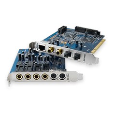
1212m PCIe System Components
E-MU 1212m
•E-MU 1010 PCIe Card
•E-MU 0202 I/O Daughter Card
•0202 I/O Card Cable
•(2) MIDI Adapter Cables
•Digital Audio System Software/Driver Installation CD-ROM
•Production Tools Software Bundle CD-ROM
•Quick Start Guide
Inputs & Outputs
(8) Channel ADAT Digital Optical Input
(8) Channel ADAT Digital Optical Output
(2) Channel S/PDIF Digital Input
(2) Channel S/PDIF Digital Output
(1)MIDI Input & Output (allows 16 MIDI channels)
(2)24-bit Balanced Line Inputs
(2) 24-bit Balanced Line Outputs
![]()
1- Introduction
Welcome!
Both Systems Include:
The E-MU 1010 PCIe Card is the heart of all three systems. Its powerful hardware DSP processor allows you to use over 16 simultaneous hardware-based effects, which place minimal load on your computer’s CPU. The E-MU 1010 PCIe Card also provides eightchannels of ADAT® optical digital input and output, as well as a S/PDIF stereo digital input and output.
The PatchMix DSP mixer application is included in all the systems. PatchMix DSP delivers unmatched flexibility in routing your audio between physical inputs and outputs, virtual (ASIO/WAVE) inputs and outputs and internal hardware effects and buses—no external mixer needed. You can add digital effects, EQs, meters, level controls and ASIO/WAVE sends anywhere you like in the signal chain.
Because the effects and mixing are hardware-based, they don’t add latency when you record. You can even record a dry signal while monitoring yourself with effects! (See “The Order of Effects” on page 57.) Mixer setups can be saved and instantly recalled for specific purposes such as recording, mixdown, jamming, special effect setups, playing games, watching DVDs, or general computer use.
E-MU 1212m System
The E-MU 1212m includes the 0202 Daughter Card, which provides 2 line level, balanced analog inputs, 2 line level, balanced analog outputs, plus MIDI input and output. This is no-compromise audio interface, using ultra-high performance 24-bit/192kHz A/D — D/A converters to deliver an unbelievable 120dB dynamic range.
E-MU 1616m System
The E-MU 1616m system includes the MicroDockm, a no compromise, mastering-grade system in a half rack-space, audio interface. The MicroDock adds the following input and output capabilities to the system: two mic/line inputs with custom low-noise preamps, 4 balanced line level analog inputs, an RIAA stereo turntable preamp, 6 balanced line level outputs, an assignable headphone output, two sets of MIDI I/O ports, an additional S/PDIF optical output, and four stereo mini phone jacks for easy connection to powered speaker systems. The 1616M system utilizes ultra-high performance 24-bit/192kHz A/D — D/A converters with automatic DC blocking to deliver an incredible 120dB of dynamic range.
Sync Daughter Card
The legacy Sync Daughter Card is NOT compatible with the 1010 PCIe card. The Sync Daughter Card was an option for the original 1010 PCI card and provided Word Clock, SMPTE and MIDI Time Code output.
S/PDIF and ADAT on the 1010 PCIe card are NOT ACTIVE when the MicroDock is connected.
|
E-MU PCIe Digital Audio Systems |
11 |

1- Introduction
Welcome!
PatchMIx DSP
PatchMix DSP offers unmatched flexibility in routing your audio between physical inputs/outputs, virtual (ASIO/WAVE) inputs/outputs, internal hardware effects and buses. No external mixer is needed. You can add digital effects, EQs, meters, level controls and ASIO/WAVE sends anywhere you like in the signal chain.
Because the effects and mixing are hardware-based, you can record using effects with near zero-latency. You can even record a dry signal while monitoring yourself with effects! (See “The Order of Effects” on page 57.) Mixer setups can be saved and instantly recalled for specific purposes such as recording, mixdown, jamming, special effect setups, playing games, watching DVDs, or general computer use.
You’ll want to keep up with the latest software and options for your E-MU digital audio system. You can find all of this, plus other helpful information, at the E-MU Website: http://www.emu.com.
Notes, Tips and Warnings
Items of special interest are presented in this document as notes, tips and warnings.
Notes provide additional information related to the topic being discussed. Often, notes describe the interaction between the topic and some other aspect of the system.
Tips describe applications for the topic under discussion.
Warnings are especially important, since they help you avoid activities that can cause damage to your files, your computer or yourself.

2 — Installation
Setting Up the Digital Audio System
2 — Installation
Setting Up the Digital Audio System
There are six basic steps to installing your E-MU system:
1.Remove any other sound cards you have in your computer. (Once you are sure that the E-MU card works properly, your old sound card can be reinstalled if desired.)
2.Install the E-MU 1010 PCIe x1 card in your computer. Go there.
3.Install the 0202 Daughter Card (if applicable). Go there.
4.Connect the MicroDock (if applicable).
5.Install the PatchMix DSP software onto your computer.
6.Connect audio, MIDI and synchronization cables between the E-MU system and your other gear.
7.After Software Installation, click on the E-MU icon  in the Windows SysTray to open PatchMix DSP, then click the ? in the upper right corner to open the complete operation manual.
Notes for Installation
•IF AT ANY TIME DURING THIS INSTALLATION YOU SEE NO RESPONSE: Use the Alt-Tab feature to select other applications. One of them may be the Microsoft Digital Signature warning. It is possible for this warning to appear behind the installation screen.
•Make sure you have the latest Windows Service Packs from Microsoft® (Windows® XP — SP 2 or higher, Vista® — SP 1 or higher).
•Disable onboard sound and uninstall all other sound cards. (If you wish to try using multiple sound cards in your system, do so after you have confirmed that your E-MU Digital Audio System is operating normally.)
•InstallShield “IKernel Application Error” on Windows XP: When installing this software on Windows XP, you may be confronted with a “kernel error” at the very end of installation. This is an issue with the InstallShield program, which is what we use to install software on your computer. Please do not be alarmed by this, as the error is innocuous.
•To read more about this error, and obtain instructions on how to avoid getting the message, please visit this website: http://support.installshield.com/kb/view.asp?articleid=q108020
•Multiple Digital Audio System sound cards are not supported.
System Requirements
•Intel® or AMD® processor operating at 1GHz or faster
•Intel, AMD or 100% compatible motherboard and chipset
•Windows XP SP2 or higher, Windows Vista SP1 or higher
•512 MB RAM
•500 MB free hard disk space for full installation
•Available PCIe 1.1 compliant slot (1 PCIe and 1 backplane slot required for 1212)
•XVGA Video (1024 x 768)
•CD-ROM drive required for software installation
•Headphones, amplified speakers, or audio sound system
|
E-MU PCIe Digital Audio Systems |
13 |

2 — Installation
Setting Up the Digital Audio System
Please read the following sections as they apply to your system as you install the E-MU 1010 PCIe, paying special attention to the various warnings they include.
Prior to installing the hardware, take a few moments to write down the 18-digit serial number, which is located on the back of the box and on the 1010 PCIe Card. This number can help EMU Customer Service troubleshoot any problems you may encounter—by writing the number down now, you’ll avoid having to open your computer to find it later on.
Safety First!
•To avoid possible permanent damage to your hardware, make sure that all connections are made with the host computer’s power off. Unplug the computer’s power cable to make sure that the computer is not in sleep mode.
•Take care to avoid static damage to any components of your system. Internal computer surfaces, the E-MU 1010 PCIe board and the interfaces are susceptible to electrostatic discharge, commonly known as “static.” Electrostatic discharge can damage or destroy electronic devices. Here are some procedures you can follow when handling electronic devices in order to minimize the possibility of causing electrostatic damage:
•Avoid any unnecessary movement, such as scuffing your feet when handling electronic devices, since most movement can generate additional charges of static electricity.
•Minimize the handling of the PCIe card. Keep it in its static-free package until needed. Transport or store the board only in its protective package.
•When handling a PCIe card, avoid touching its connector pins. Try to handle the board by its edges only.
•Before installing a PCIe card into your computer, you should be grounded. Use a ground strap to discharge any static electric charge built up on your body. The ground strap attaches to your wrist and any unpainted metal surface within your computer. If you don’t have a ground strap, you can ground yourself by touching the metal case of another piece of grounded equipment.
Connector Types
These connector types are used to connect the E-MU 1010 hardware components. They will be referred to by the name shown in the first column of the following chart:
|
Name |
Description |
Connects |
|
Card/External |
CAT5 Connector |
1010 PCIe card and MicroDock |
|
S/PDIF In |
RCA Connector |
S/PDIF digital audio devices |
|
S/PDIF Out |
RCA Connector |
S/PDIF digital audio devices |
|
ADAT Optical In |
TOSLINK Optical Connector |
ADAT digital audio devices (or S/PDIF) |
|
ADAT Optical Out |
TOSLINK Optical Connector |
ADAT digital audio devices (or S/PDIF) |
ý Warning: Please verify that all cables are connected only to the proper components before powering up your system.
As you install hardware components, observe the following general precautions to avoid damage to your equipment and yourself.

2 — Installation
Installing the E-MU 1010 PCIe Card
Installing the E-MU 1010 PCIe Card
This installation is very simple but if you are not familiar with the installation of computer peripherals and add-in boards, please contact your authorized E-MU Systems dealer or an approved computer service center to arrange for the installation.
IMPORTANT: Remove any other audio cards and uninstall the audio card or motherboard audio software from your PC before installing this card.
Once the Digital Audio System has been successfully installed and is working properly, you MAY be able to install another audio card if you so desire.
To install the 1010 PCIe card into your computer
1.Make sure that the power switch on your computer is off.
IMPORTANT: Unplug the power cord from the wall outlet!
2.Touch a metal plate on your computer to ground yourself and to discharge any static electricity.
3.Follow the computer manufacturer’s recommended procedure for opening the case.
4.Remove the metal bracket from one PCIe x1 slot. (PCIe x1 slots are the smallest of the PCie slots.) If you have the E-MU 1212M system, you’ll need to remove the bracket from two slots. Put the screw(s) aside for use later. See figure 1 below.
|
Figure 1 |
|||||
|
PCIe |
|||||
|
x16 |
|||||
|
(may |
PCIe |
||||
|
PCI |
PCIe |
||||
|
on |
x1 |
||||
|
not |
x1 |
||||
|
your |
be |
||||
|
Slots |
|||||
|
present |
|||||
|
computer) |
|
Figure 2 |
||||
|
PCIe |
||||
|
x16 |
||||
|
(may |
PCI |
PCIe |
||
|
on |
||||
|
not |
x1 |
|||
|
your |
be |
|||
|
Slots |
||||
|
present |
||||
|
computer) |
Note: Some computer cases don’t use screws to secure PCIe cards. In this case, follow the instructions that came with your computer.
5.Align the E-MU 1010 PCIe card with the slot and press gently but firmly down into the slot as shown in figure 2.
6.Do not force the E-MU 1010 PCIe card into the slot. Make sure that the gold finger connector of the card is aligned with the PCIe x1bus connector on the motherboard before you insert the card into the PCIe slot. If it doesn’t fit properly, gently remove it and try again.
7.Secure the card into the slot using one of the screws you placed aside earlier.
|
E-MU PCIe Digital Audio Systems |
15 |

2 — Installation
1212m Owners — Install the 0202 Daughter Card
1212m Owners — Install the 0202 Daughter Card
1.Unwrap the 0202 Daughter Card and get ready to install it.
2.Connect the provided ribbon cable between the E-MU 1010 PCIe card and the 0202 Daughter card as shown in figure 3. The cable is keyed so it cannot be incorrectly inserted. Seat the connectors firmly in the sockets and arrange the cable neatly.
3.Align the 0202 Daughter Card with the back panel slot and press gently but firmly down into the slot as shown in figure 2 on the preceding page.
4.Do not force the 0202 Daughter Card into the slot. The bottom of the card does not fit into the PCIe slot. The rear panel mounting holds it in place.
5.Secure the card into the slot using one of the screws you placed aside earlier.
6.After all components have been installed and securely fastened, close the computer case.
|
Figure 3 |
|||||
|
PC |
PC |
||||
|
I |
|||||
|
PC |
I |
e |
|||
|
e |
x1 |
||||
|
I |
x1 |
||||
|
S |
|||||
|
l |
|||||
|
ots |
|||||
|
0202 |
|||||
|
Daughter Card |
7.Connect the supplied network-type cable from the 10 BaseT jack on the E-MU 1010 PCIe card labeled “EDI” to the matching connector labeled “EDI” on the MicroDock. The cable supplied with the MicroDock is specially shielded to prevent unwanted RF emissions.
8.Plug the power cord back into the wall outlet and turn on your computer.
Connecting the MicroDock
1.Connect the supplied EDI cable between the 1010 PCIe Card and the MicroDock.
2.Connect the supplied +48 volt DC adapter to the +48VDC jack on the rear of the MicroDock. See the diagram below.
3.Connect your audio inputs and outputs to the MicroDock as shown on page 25.
4.Turn the MicroDock on by turning the Headphone Volume control.
+48V DC Adapter
48VDC + 
 —
—
The Headphone
EDI
Volume Control is the Power Switch.
1010 PCIe Card
CAUTION: Do not connect the supplied CAT5 cable to the Ethernet or network connector on your computer. Doing so may result in permanent damage to either your computer, the E-MU 1010 or both.
Note: The 1616m MicroDocks cannot be used with older 1010 PCI cards identified by the 1394 FireWire port.

2 — Installation
Connecting the MicroDock
ý Warning: The MicroDock has been designed to use readily available and inexpensive standard computer system cables. This makes it easy for you to find replacement cables if your original cable becomes damaged or lost. However, because these standard cables types are used for other purposes, you must use caution to avoid connecting the cables incorrectly. DO NOT connect the supplied EDI cable to the Ethernet or network connector on your computer. Doing so may result in permanent damage to either your computer, the E-MU 1010 PCIe card, or the MicroDock.
WARNING: E-MU 0202 & MicroDock
If you have both the E-MU 0202 I/O card and the MicroDock, DO NOT connect both to the E-MU 1010 PCIe card. They cannot be used together.
|
E-MU PCIe Digital Audio Systems |
17 |

2 — Installation
Software Installation
Software Installation
Installing the E-MU 1010 PatchMix Software and Drivers
The first time you restart your PC after installing the E-MU 1010 PCIe card, you will need to install the PatchMix DSP software and E-MU 1010 PCIe card drivers.
Windows XP, Windows XP x64, Windows Vista, Windows Vista x64
The software is not compatible with other versions of Windows.
1.After you have installed your Digital Audio System, turn on your computer. Windows automatically detects the Digital Audio System and searches for device drivers.
2.When prompted for the audio drivers, click the Cancel button.
3.Insert the E-MU software Installation CD into your CD-ROM drive. If Windows AutoPlay mode is enabled for your CD-ROM drive, the CD starts running automatically. If not, from your Windows desktop, click Start->Run and type d:setup.exe (replace d: with the drive letter of your CD-ROM drive). You can also open the CD and double-click Setup.exe.
4.The installation splash screen appears. Follow the instructions on the screen to complete the installation.
5.Choose “Continue Anyway” when you encounter the “Windows Logo Testing” warning screen. See the note below for more information.
6.When prompted, restart your computer.
Uninstalling all Audio Drivers and Applications
At times you may need to uninstall or reinstall some or all of the audio card’s applications and device drivers to correct problems, change configurations, or upgrade outdated drivers or applications. Before you begin, close all audio card applications. Applications still running during the uninstallation will not be removed.
1.Click Start -> Settings -> Control Panel.
2.Double-click the Add/Remove Programs icon.
3.Click the Install/Uninstall tab (or Change or Remove Programs button).
4.Select the E-MU driver/application entries and then click the Add/Remove (or Change/Remove) button.
5.In the InstallShield Wizard dialog box, select the Remove option.
6.Click the Yes button. Restart your computer when prompted.
7.You may now re-install existing or updated E-MU 1010 PCIe card device drivers or applications.
Note About Windows Logo Testing
When you install the 1616M PCIe drivers, you will see a dialog box informing you either that the driver has not been certified by Windows Hardware Quality Labs (WHQL), or that the driver is signed by Creative Labs, Inc, and you will be asked if you would like to continue with the installation.
The 1616m PCIe audio drivers are not certified by WHQL because the product does not support some of the features that the Microsoft Windows Logo Program requires, most notably Universal Audio Architecture (UAA) and Digital Rights Management (DRM).
Despite this, the 1616M PCIe audio drivers have been rigorously tested using the same test procedures that a WHQL qualified driver requires, and it passes in all of the other important categories, including those that measure the relative stability of the driver.
So, it is perfectly safe to install these drivers on your computer.
Serial Number — During the registration process, you will be asked to enter your 18-digit serial number. The serial number is located on the back of the box and on the 1010 PCIe Card.

3 — PCIe Card & Interfaces
The E-MU 1010 PCIe Card
The E-MU 1010 PCIe card is the heart of the system and contains E-MU’s powerful E-DSP chip. The powerful hardware DSP on this card leaves more power free on your CPU for additional software plug-ins and other tasks.
Important
When the MicroDock is connected to the 1010 PCIe card, the digital I/O on the PCIe card is disabled. Use the digital I/O on the MicroDock.
Connections
Connects to MicroDock via EDI Cable
S/PDIF
In/Out
ADAT or S/PDIF Optical In/Out
EDI Connector
Connects to the MicroDock using the supplied EDI
cable. This cable provides a a two-way data link
(‘, between the E-MU 1010 and the MicroDock as well as supplying power to the MicroDock.
S/PDIF Digital Audio Input & Output
RCA phono jacks are standard connectors used for S/PDIF (Sony/Philips Digital InterFace) connections. Each jack carries two channels of digital audio.
The E-MU 1010 receives digital audio data with word lengths of up to 24-bits. Data is always transmitted at 24-bits.
S/PDIF digital I/O can be used for the reception and/ or transmission of digital data from external digital devices such as a DAT external analog-to-digital converter or an external signal processor equipped with digital inputs and outputs.
The S/PDIF out can be configured in either Professional or Consumer mode in the Session Settings menu. The 1010 PCIe card can also send and receive AES/EBU digital audio through the use of a cable adapter. See “AES/EBU to S/PDIF Cable Adapter” for details.
The S/PDIF input and outputs are usable at the 44.1kHz, 48kHz 88.2kHz and 96kHz sample rates, but are disabled for 176.4kHz and 192kHz. The word clock contained in the input data stream can be used as a word clock source. See “System Settings”.
ADAT Optical Digital Input & Output
The ADAT optical connectors transmit and receive 8 channels of 24-bit audio using the ADAT type 1 & 2 formats. The word clock contained in the input data stream can be used as a word clock source. See “System Settings”. Optical connections have certain advantages such as immunity to electrical interference and ground loops. Make sure to use high quality glass fiber light pipes for connections longer than 1.5 meters.
3 — PCIe Card & Interfaces
The E-MU 1010 PCIe Card
S/PDIF and ADAT on the 1010 PCIe card are NOT ACTIVE when the MicroDock is connected.
Important: When using any type of digital I/O such as S/PDIF or ADAT, you MUST sample sync the two devices or clicks and pops in the audio will result.
|
E-MU PCIe Digital Audio Systems |
19 |

3 — PCIe Card & Interfaces
The 0202 Daughter Card
At the 96kHz or 192kHz sample rates, the industry standard S/MUX interleaving scheme is used for ADAT input and output. S/MUX uses additional ADAT channels to achieve the required bandwidth. See the chart below or go here for additional information.
|
Sample Rate |
Number of Audio Channels |
|
44kHz/48kHz |
8 channels of 24-bit audio |
|
88.2kHz/96kHz |
4 channels of 24-bit audio, using S/MUX standard |
|
176.4kHz/192kHz |
2 channels of 24-bit audio, using S/MUX standard |
The 0202 Daughter Card
The 0202 Daughter card is the companion card for E-MU 1010 systems which don’t include the MicroDock. The 0202 Daughter card provides one pair of 24-bit balanced analog inputs and one pair of 24-bit balanced analog outputs, plus MIDI in and out.
Connections
Left / Right 
Line Inputs 
Left / Right 
Line Outputs 
MIDI 
In/Out 


Analog Inputs and Outputs
The 0202 Daughter Card provides two balanced, analog inputs and two balanced, line level analog outputs. The inputs can be connected to any line level stereo signal from keyboards, CD-players, cassette decks, etc. The analog inputs are assigned to a mixer strip in the mixer application.
The outputs can feed any line level input such as a mixing board, the auxiliary input on your stereo or a set of powered speakers. The line outputs are NOT designed to drive headphones directly. Connect the line outputs to a stereo receiver or mixer with a headphone jack to obtain the proper current drive.
Either TRS (tip-ring-sleeve) balanced or TS unbalanced cables can be used. Balanced cables provide better noise immunity and +6dB higher signal level. The output line level can be set to accommodate the consumer -10dBV standard, or the pro audio +4 dBu standard in the I/O screen of the Session Settings dialog box. See “I/O Settings”.
MIDI In/Out
The MIDI input and output port can be assigned in your specific MIDI application. Connect the MIDI adapter cable that came with your 0202 Daughter card to the miniDIN connectors on the card. The adapter cables convert the mini-DIN to standard DIN connectors used on most keyboards and synthesizers. Connect MIDI Out to the MIDI In port of your synthesizer and MIDI Out of your synth to MIDI In of the 0202 Daughter Card.
![]()
The MicroDock
The MicroDock connects to the E-MU 1010 PCIe card via the EDI cable.
The MicroDock provides (4) balanced analog inputs, (2) microphone preamp inputs,
(6) balanced line-level analog outputs, (3) stereo 1/8” outputs for connecting powered computer speakers, (2) MIDI inputs, (2) MIDI outputs, a stereo headphone output, and a RIAA equalized turntable preamp section which is “normalled” into line input 2L and 2R, 8 channels of ADAT digital input/output, and stereo S/PDIF digital input/ output.
|
A Line |
Mic |
B Line |
Mic |
S/PDIF |
|||
|
Clip |
-3 |
Clip |
-3 |
48V |
|||
|
SL |
-6 |
SL |
-6 |
||||
|
-12 |
-12 |
||||||
|
-20 |
-20 |
|
Line — |
-15 |
+50 |
-15 |
+50 |
O |
|||||||||
|
Mic — |
0 |
+65 |
0 |
+65 |
||||||||||
|
1L |
1R |
2L |
2R |
2L Phono 2R |
Gnd |
MIDI Cable |
||||||||
|
In |
48VDC |
|||||||||||||
|
+ — |
||||||||||||||
|
Out |
||||||||||||||
|
1 |
2 |
3 |
||||||||||||
|
Out |
EDI |
|||||||||||||
|
1L |
1R |
2L |
2R |
3L |
3R |
|||||||||
|
The inputs are configured as follows: |
||||||||||||||
|
(2) |
mono microphone/line inputs (2 inputs) |
|||||||||||||
|
(2) |
stereo pairs of line level inputs (4 inputs) |
|||||||||||||
|
(1) |
stereo pair of S/PDIF/AES digital inputs (2 inputs) |
|||||||||||||
|
(4) |
stereo pairs of ADAT channels on the ADAT optical input (8 inputs) |
|||||||||||||
|
(1) |
RIAA equalized turntable preamp input allows you to connect a turntable |
|||||||||||||
|
without using an expensive external preamp. Note: These inputs are automati- |
||||||||||||||
|
cally disconnected when plugs are inserted into inputs 2L & 2R. |
||||||||||||||
|
(2) |
MIDI input ports using the supplied breakout cable |
|||||||||||||
|
The outputs are configured as: |
||||||||||||||
|
(3) |
Stereo pairs of line level outputs |
|||||||||||||
|
(1) |
Stereo pair driving a stereo headphone jack (Share the same routing as Line |
|||||||||||||
|
Outs 1L/1R) |
||||||||||||||
|
(1) |
Stereo pair of S/PDIF/AES digital outputs |
|||||||||||||
|
(4) |
Stereo pairs of ADAT channels on the ADAT optical output |
|||||||||||||
|
(3) |
Stereo 1/8” computer speaker outputs. These outputs carry the same signals as |
|||||||||||||
|
the 3 stereo line level outputs and are provided as a convenience for connecting |
||||||||||||||
|
computer or powered speaker systems. |
||||||||||||||
|
(2) |
MIDI output ports using the supplied breakout cable |
|||||||||||||
3 — PCIe Card & Interfaces
The MicroDock
The MicroDock is completely “hot pluggable”— It’s OK to plug or unplug the MicroDock while the computer is turned on.
It’s a good idea to mute MicroDock inputs 2 in the PatchMix DSP mixer when nothing is plugged in, since the turntable preamp has a very high gain (60dB) and could contribute extra noise to your mix/monitor bus.
|
E-MU PCIe Digital Audio Systems |
21 |

3 — PCIe Card & Interfaces
The MicroDock
Front Panel Connections
Preamp Section
The front panel mono Mic/Line inputs A & B can be used as balanced microphone inputs, hi-Z guitar pickup inputs, or line level inputs. The Neutrik combination jack accepts microphones using a standard XLR connector or line level/hi-Z inputs (such as an electric guitar) using a standard 1/4 inch TRS/TS connector.
Each preamp has a level control which sets the preamp gain from 0dB to +65dB for the XLR input and from -15dB to +50dB for the Hi-Z line input. The line markings around the knobs are calibrated in 10dB increments. The heavy hash marks on the gain controls indicate unity analog gain to the converter inputs (~5dBV input = 0dBFS output).
A phantom power switch enables +48 volt phantom power supplied to both microphones. A red LED illuminates to indicate phantom power is enabled. The audio mutes for a second when phantom power is turned on. After turning phantom power off, wait two full minutes before recording to allow the DC bias to drain. See “Phantom Power” for additional information.
Each microphone input has its own input level meters and clipping indicators. The LED meters indicate signal presence. Adjust the input gain so that the yellow LEDs are illuminated. The red Clip LED indicates that the gain is set too high and the signal is clipping the input. These LEDs monitor the signal directly at the analog-to-digital converters and before any processing by the rest of the system. When setting the levels for signals being sent into the MicroDock, the red clip indicator should never flash.
S/PDIF Digital Audio Input & Output
RCA phono jacks are standard connectors used for coaxial S/PDIF (Sony/Philips Digital InterFace) connections. Each jack carries two channels of digital audio. The MicroDock sends or receives digital audio data at 44.1k, 48k, 88.2k, 96k, 176.4k or 192k sample rates. Data is always transmitted at 24-bits, but lower word widths can be read. The word clock contained in the input data stream can be used as a word clock source. See “System Settings”.
S/PDIF digital I/O can be used for the reception and/ or transmission of digital data from external digital devices such as a DAT, external analog-to-digital converter or an external signal processor equipped with digital inputs and outputs.
The S/PDIF out can be configured in either Professional or Consumer mode in the Session Settings menu. The MicroDock can also send and receive AES/EBU digital audio through the use of a cable adapter. See “Cables — balanced or unbalanced?” for details.
Phantom Power Caution: Some microphones (notably ribbon types) cannot tolerate phantom power and may be damaged. Check the specifications and requirements of your microphone before using phantom power.

ADAT Optical Digital Input & Output
The ADAT optical connectors transmit and receive 8 channels of 24-bit audio using the ADAT type 1 & 2 formats. The word clock contained in the input data stream can be used as a word clock source. See “System Settings”. Optical connections have certain advantages such as immunity to electrical interference and ground loops. Make sure to use high quality glass fiber light pipes for connections longer than 1.5 meters.
At the 88.2k, 96k, 176.4k or 192k sample rates, the industry standard S/MUX interleaving scheme is used for ADAT input and output. S/MUX uses additional ADAT channels to gain additional bandwidth on the existing interface. See the chart below or go here for additional information.
|
Sample Rate |
Number of Audio Channels |
|
44kHz/48kHz |
8 channels of 24-bit audio |
|
88kHz or 96kHz |
4 channels of 24-bit audio, using S/MUX standard interleaving |
|
176kHz or 192kHz |
2 channels of 24-bit audio, using S/MUX standard interleaving |
The ADAT inputs and outputs can be configured in the System Settings (page 33) to send and receive S./PDIF optical data at 44.1k, 48k, 88.2k, or 96k sample rates.
S/PDIF Optical is not supported at 176.4k or 196k.
Headphone Output & Volume Control
The headphone output drives standard stereo headphones and the adjacent volume control sets the listening level. The headphone amplifier can drive headphones with impedance as low as 24 ohms. The headphone output uses a high-current version of the high-quality output amplifiers used on the other channels. For this reason it has a very clean signal that can be used as another stereo output if you need it.
3 — PCIe Card & Interfaces
The MicroDock
Important: When using any type of digital I/O such as S/PDIF or ADAT, you MUST sample sync the two devices or clicks and pops in the audio will result.
Note: PatchMix DSP does not support AC3 passthrough at this time.
|
E-MU PCIe Digital Audio Systems |
23 |

3 — PCIe Card & Interfaces
The MicroDock
Front Panel
Analog Connections
Use the 3-pin XLR jack for Low Impedance microphones.
Use the center
Phone Jack for High Impedance instruments such as electric guitar or bass.
|
Digital Connections |
Out |
External A/D — D/A Converter |
||||||||
|
1 |
2 |
3 |
4 |
5 |
6 |
7 |
8 |
|||
|
In |
(8 more analog inputs & outputs) |
|||||||||
|
Optical |
||||||||||
|
ADAT |
In |
DAT or CD |
||||||||
|
(Optical) |
Out |
|||||||||
|
Digital Audio Device with S/PDIF |
||||||||||
|
Out |
||||||||||
|
S/PDIF |
In |
Coaxial |
In |
|||||||
|
(Coax) |
Out |
MIDI Out MIDI Keyboard |
Audio Outs |
|||||||
|
In |
EMULATOR |
|
|
MIDI 1 |
MIDI In |
|
|
Out |
||
|
MIDI Sound Module |
Audio Outs |
|||
|
In |
||||
|
I O |
1 |
2 |
3 |
|
|
SAMPLE |
TRIGGERS |
|||
|
MIDI 2 |
PRESET |
|||
|
4 |
5 |
6 |
||
|
VOLUME |
||||
|
7 |
8 |
9 |
||
|
MIDI In |
0 |
MIDI |
||
|
Out |

Rear Panel Connections
|
4 Balanced Line Level Inputs |
Turntable Inputs |
Turntable |
MIDI Port |
48 Volt DC |
|||||||
|
(configured as 2 stereo pairs) |
(tied to line input 2) |
Ground |
Connector |
Power Input |
|||||||
|
1L |
1R |
2L |
2R |
2L Phono 2R |
Gnd |
MIDI Cable |
|||||
|
In |
48VDC |
||||||||||
|
+ |
— |
||||||||||
|
Out |
|||||||||||
|
1 |
2 |
3 |
|||||||||
|
Out |
EDI |
||||||||||
|
1L |
1R |
2L |
2R |
3L |
3R |
||||||
|
6 Balanced Line Level Outputs |
Alternate Outputs |
Connect to |
|||||||||
|
(configured as 3 stereo pairs) |
(same as outputs 1-3) |
E-MU 1010 PCIe Card |
Line Level Analog Inputs
4 balanced 24-bit, line-level, analog inputs are provided (1L-1R, 2L-2R). These can be used to input any line level signal from keyboards, CD-players, cassette decks, etc. The analog inputs are assigned to mixer strips in the mixer application. The line level inputs can be set to accommodate the consumer -10dBV standard, or the pro audio +4 dBu standard in the I/O screen of the Session Settings dialog box. See “I/O Settings”.
The maximum input level is 18dBV (=20.2dBu).
Either TRS balanced or TS unbalanced cables can be used. The line-level inputs are all servo-balanced, enabling them to convert unbalanced signals to balanced signals internally to reduce noise. See page 115 for additional information about unbalanced cables and connectors.
Phono Inputs & Ground Lug
The RCA Phono inputs feed an RIAA equalized preamp designed for moving magnet type phono cartridges with 60 dB of gain. Connect the ground lead from your turntable to the ground lug to prevent hum.
The phono inputs SHARE line level inputs 2L and 2R. Inserting a plug into Line Input 2 disconnects the turntable preamp from that channel. Do NOT leave your turntable connected when using inputs 2L and 2R, since this can cause a ground loop.
Important: Do NOT plug in line level signals to the turntable inputs. The turntable inputs are designed to accept the extremely low-level signal from a phonograph cartridge. Use RCA to 1/4” adapters to connect line level signals to the line level analog inputs.
Line Level Analog Outputs
Six balanced 24-bit, line-level, analog outputs are provided (1-3). Output pair 1 is designated as the Monitor Output and is fed by the monitor bus of the PatchMix DSP mixer application. We suggest that you plug your speakers in here. Special anti-pop circuitry mutes the analog outputs when power is turned on or off.
Like the analog line inputs, either TRS balanced or TS unbalanced cables can be used. Balanced cables provide better noise immunity and +6dB higher signal level. The output line level can be set to accommodate the consumer -10dBV standard, or the pro audio +4 dBu standard in the I/O screen of the Session Settings dialog box. See “I/O Settings”.
The maximum input and output line levels are matched when the input and output settings are set to the same mode (pro or consumer) in the I/O preferences screen.
3 — PCIe Card & Interfaces
The MicroDock
Important!
It’s a good idea to MUTE the Dock In strip 2L/2R in the PatchMix DSP mixer if nothing is plugged in to these jacks. The turntable preamp has a very high gain (60dB) and can add extra noise to your mix/ monitor bus.
Balanced Cables:
You should ONLY use balanced (TRS) cables if BOTH pieces of equipment use balanced connections. Connecting balanced cables between balanced outputs and unbalanced inputs can actually increase noise and introduce hum.
|
E-MU PCIe Digital Audio Systems |
25 |

3 — PCIe Card & Interfaces
The MicroDock
Computer Speaker Analog Outputs
These stereo mini-phone (3.5mm) jacks duplicate line level outputs 1-3 with a lower output level to accommodate consumer speakers. These line level outputs are designed to interface easily with powered speakers.
|
Computer Speaker Output |
Duplicates Line Level Output |
|
|
1 L/R |
Tip = 1L |
Ring = 1R |
|
2 L/R |
Tip = 2L |
Ring = 2R |
|
3 L/R |
Tip = 3L |
Ring = 3R |
MIDI 1 & 2 In/Outs
MIDI input and output ports allow you to interface any type of MIDI equipment such as keyboards, effect units, drum or guitar controllers (anything with MIDI). The MIDI drivers were installed when you installed your PatchMix DSP software and the MIDI ports will appear in your system control panel under “Sounds and Audio Devices.”
There are two completely independent sets of MIDI input and output ports on the MicroDock, which can be assigned in your specific MIDI applications.
Connect the MIDI breakout cable to the D-connector on the MicroDock. Connect MIDI Out to the MIDI In port of your synthesizer and MIDI Out of your synth to MIDI In of the MicroDock MIDI cable.
EDI Connector (Card)
Connects the MicroDock to the E-MU 1010 PCIe card using a CAT5-type computer cable. The cable supplied with the MicroDock is specially shielded to prevent unwanted RF emissions.
|
MIDI Out |
In |
||||||||||||||||||||||||
|
Audio |
|||||||||||||||||||||||||
|
from |
|||||||||||||||||||||||||
|
Synthesizer |
|||||||||||||||||||||||||
|
* |
* |
||||||||||||||||||||||||
|
2L Phono |
2R Gnd |
MIDI Cable |
|||||||||||||||||||||||
|
1L |
1R |
2L |
2R |
||||||||||||||||||||||
|
In |
48VDC |
||||||||||||||||||||||||
|
+ — |
|||||||||||||||||||||||||
|
AC Adapter |
|||||||||||||||||||||||||
|
Out |
|||||||||||||||||||||||||
|
1 |
2 |
3 |
|||||||||||||||||||||||
|
Out |
EDI |
||||||||||||||||||||||||
|
1L |
1R |
2L |
2R |
3L |
3R |
1010 PCIe |
|||||||||||||||||||
|
Card |
|||||||||||||||||||||||||
|
Audio |
Connect |
||||||||||||||||||||||||
|
Desktop |
|||||||||||||||||||||||||
|
to |
Powered |
||||||||||||||||||||||||
|
Monitors |
Speakers to |
Desktop |
|||||||||||||||||||||||
|
1/8″ jacks |
|||||||||||||||||||||||||
|
Speakers |
|||||||||||||||||||||||||
|
r |
|||||||||||||||||||||||||
|
te e |
o |
||||||||||||||||||||||||
|
S |
Mixer
&
Speakers
* NOTE: Line Inputs 2L/2R and Phono 2L/2R cannot be used at the same time.

3 — PCIe Card & Interfaces
The MicroDock
|
5.1 Surround Speaker Connections |
|||||||||||
|
Center |
|||||||||||
|
Left |
1L |
1R |
2L |
2R |
2L Phono 2R |
Gnd |
MIDI Cable |
Right |
|||
|
48VDC |
|||||||||||
|
Front |
In |
Front |
|||||||||
|
+ |
— |
||||||||||
|
Out |
|||||||||||
|
1 |
2 |
3 |
|||||||||
|
Out |
EDI |
||||||||||
|
1L |
1R |
2L |
2R |
3L |
3R |
||||||
|
Left |
Right |
||||||||||
|
Rear |
Rear |
||||||||||
|
Front |
Rear |
Ctr/Sub |
|||||||||
|
Sub-Woofer |
|||||||||||
|
(with built-in power amps) |
The 1/8” stereo jacks make it easy to connect to powered surround sound speakers. Only three stereo cables are necessary with many speaker systems (see above). The 1/8” jacks duplicate the 1/4” outputs. The 1/8” jacks and the 1/4” jacks can be used simultaneously.
You can connect the 1/8” stereo jacks to your surround speakers and connect the 1/4” outputs to your other gear for music creation. (Yes, they can both be connected at the same time.) When you want to monitor in surround, simply open the 5.1 Session and turn on your surround speakers.
The chart below shows how to connect the outputs for 5.1 surround sound playback.
Multichannel WAVE to Surround Sound Speaker Channels
(using the factory 5.1 DVD Playback Session)
|
WAVE Strip |
Surround Channels |
1/4” Outputs |
1/8” Outputs |
|||
|
E-DSP WAVE 1/2 Front Left/Front Right |
1L |
= FL |
1R = FR |
1 |
(Tip = FL |
Ring = FR) |
|
E-DSP WAVE 3/4 |
Center/Subwoofer |
3L |
= C 3R = Sub |
3 |
(Tip = C |
Ring = Sub) |
|
E-DSP WAVE 5/6 Rear Left/Rear Right |
2L |
= RL |
2R = RR |
2 |
(Tip = RL |
Ring = RR) |
|
E-DSP WAVE 7/8 Side Left/Side Right |
N/A |
N/A |
Choose one of the DVD 5.1 Sessions, then set up your DVD application to use multichannel WAV for audio.
|
E-MU PCIe Digital Audio Systems |
27 |

3 — PCIe Card & Interfaces
1212m System Connections
1212m System Connections
The 1212M System uses line level inputs and outputs. Microphones and unpowered instruments require a preamp since they generate signals much lower than line level. The diagram below shows how to connect to a mixer. If you don’t own a mixer, you can connect powered speakers directly to the L/R Outputs and use PatchMix as your mixer.
|
1212M Analog Connections |
|||
|
Microphone |
|||
|
(must be pre-amped) |
|||
|
L/R |
Main |
Electronic Keyboard |
|
|
Input |
Outs |
||
|
EMULATOR |
|||
|
L/R |
Input |
||
|
Output |
Strips |
||
|
Use either Balanced |
Mixer (with pre-amp) |
||
|
or Unbalanced cables |
|||
|
Electric Instrument |
|||
|
Instr. Preamp |
(must be pre-amped) |
||
Output Connections
This diagram shows the various types of cable adapters needed to connect to various types of equipment. The diagram is applicable to either the 1616M or1212M.
|
1212M Analog Output Connections |
|||
|
To Mixer |
|||
|
Inputs |
|||
|
1/4″ male to 1/4″ male |
Mixer & |
||
|
Powered Speakers |
|||
|
L |
(balanced or unbalanced) |
||
|
R |
or… |
||
|
Aux Inputs |
|||
|
Mono 1/4″ male to |
Integrated |
||
|
male Cinch (RCA) adapter |
Amp & Speakers |
||
|
or… |
|||
|
Powered |
|||
|
Desktop |
|||
|
Speakers |
|||
|
Stereo |
|||
|
Mono 1/4″ male to |
|||
|
Stereo 1/8″ female adapter |
|||
|
28 |
Creative Professional |

4 — The PatchMix DSP Mixer
PatchMix DSP
4 — The PatchMix DSP Mixer
PatchMix DSP
The PatchMix DSP Mixer is a virtual console which performs all of the functions of a typical hardware mixer and a multi-point patch bay. With PatchMix, you may not even need a hardware mixer. PatchMix DSP performs many audio operations such as ASIO/ WAVE routing, volume control, stereo panning, equalization, effect processing, effect send/return routing, main mix and monitor control and allows you to store and recall these “Sessions” at will.
To Invoke the PatchMix DSP Mixer
1.Left-click once on the E-MU icon  on the Windows System Tray. The PatchMix DSP mixer window appears.
Overview of the Mixer
|
Add New |
Physical Input Strips |
ASIO Input Strip |
Toolbar |
||
|
Strip |
|||||
Delete
Strip
Click on the buttons and knobs in the mixer screen below to jump to the description of the control.
Display
Select
Buttons
|
Channel |
“TV” |
|||||||||||||
|
Screen |
||||||||||||||
|
Insert |
||||||||||||||
|
Section |
||||||||||||||
|
Pan |
||||||||||||||
|
Controls |
Aux |
|||||||||||||
|
Aux |
||||||||||||||
|
Sends |
Effects |
|||||||||||||
|
Section |
||||||||||||||
|
Sync/ |
||||||||||||||
|
Volume |
Sample |
|||||||||||||
|
Rate |
||||||||||||||
|
Fader |
||||||||||||||
|
Indicators |
||||||||||||||
|
Solo/Mute |
||||||||||||||
|
Buttons |
||||||||||||||
|
Monitor |
||||||||||||||
|
User |
Volume/Balance |
|||||||||||||
|
/Mute Controls |
||||||||||||||
|
Definable |
||||||||||||||
|
WAVE Strip |
Main |
Current |
Main Mix |
|||||||||||
|
Scribble Strip |
||||||||||||||
|
Controls Windows Source Audio |
Inserts |
Session |
Output Volume |
|||||||||||
|
(Direct Sound, Windows Media, etc.) |
Name |
& Meters |
|
E-MU PCIe Digital Audio Systems |
29 |

4 — The PatchMix DSP Mixer
Overview of the Mixer
Mixer Window
The Mixer consists of four main sections.
|
Application Toolbar |
Lets you manage sessions and show/hide the various views. |
|
Main Section |
Controls all the main levels, aux buses, and their inserts. This section also has a “TV” |
|
which shows parameters for the currently selected effect and the input/output |
|
|
patching. It also shows the session’s current sample rate and whether it’s set to |
|
|
internal or external clock. |
|
|
Mixer Strips |
This section is located to the left of the Main Section and shows all the currently |
|
instantiated mixer strips. Mixer strips can represent Physical analog/digital inputs, or |
|
|
Host inputs such as ASIO or Direct Sound. Mixer strips can be added or deleted as |
|
|
necessary. This section can be resized by dragging the left edge of the frame. |
|
|
Effects Palette |
This popup window is invoked by pressing the FX button in the toolbar. Iconic |
|
representations of all effects presets are shown here, organized by category. From |
|
|
this window, you can drag and drop effect presets into the insert slots available on |
|
|
the mixer strips and main section aux buses and main inserts. |
|
A simplified diagram of the mixer is shown below.
IMPORTANT: Study this diagram to understand how the PatchMix DSP Mixer works.
|
Input |
Input |
Mixer Block Diagram |
|
Post-Fader Strip |
Pre-Fader Strip |
|
Insert |
Insert |
||||
|
Section |
Section |
||||
|
Panning |
|||||
|
Fader |
Aux |
Meter |
|||
|
MUTE |
Send |
Return |
|||
|
Effects |
|||||
|
Aux 1 |
Aux 1 |
||||
|
Aux |
Amount |
Amount |
|||
|
Bus 1 |
Insert |
Monitor |
|||
|
Section |
|||||
|
Out |
|||||
|
Aux 2 |
Aux 2 |
Send |
Return |
||
|
Aux |
Amount |
Amount |
MUTE |
||
|
Bus 2 |
Insert |
Output 1L/1R |
|||
|
& Headphones |
|||||
|
Section |
|||||
|
Fader |
Main Bus |
||||
|
Monitor |
|||||
|
Effects |
|||||
|
MUTE |
Level |
||||
|
Insert |
|||||
|
Main Bus |
Section |
Main |
|||
|
Main |
|||||
|
Level |
Out |
Pre Fader or Post Fader
When creating a new Mixer Strip, you have the option for the Aux Sends to be placed
Post Fader (both Aux Sends come after the channel fader) or Pre Fader (both Aux
Sends come before the channel fader). The Pre-fader option allows you to use either
Aux Send as another mix bus, which is unaffected by the channel fader.
More Information.
![]()
4 — The PatchMix DSP Mixer
E-MU Icon in the Windows Taskbar
E-MU Icon in the Windows Taskbar
Right-clicking on the E-MU icon in the Windows taskbar calls the following window.
Right-Click Here
Opens the PatchMix DSP Mixer.
Calls the PatchMix DSP help system.
 Disables the splash screen that appears at boot-up.
When unchecked, FX are not loaded until needed, resulting in faster computer boot.
Restores the default PatchMix DSP and driver settings.
Closes the PatchMix DSP background program, disabling use of all audio I/O from the E-MU hardware. Open the PatchMix DSP application to start audio again.
Restore Defaults: Always try this option first if PatchMix is crashing or if you are having any other strange audio problems.
The Toolbar
|
New |
Save |
“About” |
Session |
|
|
Session |
Session |
PatchMix DSP |
Settings |
HELP |
|
Open |
Show/Hide |
Global |
|
Session |
Effects |
Prefs |
|
New Session |
Calls up the “New Session” dialog box. New Session. |
|
Open Session |
Calls up the standard “Open” dialog box, allowing you to |
|
open a saved Session. |
|
|
Save Session |
Calls up the standard “Save” or “Save As…”þdialog boxes, |
|
allowing you to save the current Session. |
|
|
Show/Hide Effects |
Toggle button that shows or hides the FX palette. |
|
Session Settings |
Calls up the Sessions Settings window. Session Settings. |
|
Global Preferences |
Calls up the Global Preferences window. |
|
About PatchMix |
Right-Click on the E-MU logo to view the “About PatchMix |
|
DSP |
DSP” screen, which provides the software and firmware |
|
version numbers and other information. |
|
Click the buttons in the toolbar to learn about their function.
|
E-MU PCIe Digital Audio Systems |
31 |

4 — The PatchMix DSP Mixer
The Session
The Session
The current state of the PatchMix DSP mixer (fader settings, effects routings…everything!) can be saved as a Session. Whenever you create or modify a mixer setup, all you have to do is Save it to be able to recall it at a later time.
Before you begin using PatchMix DSP, you need to set it up to be compatible with the other software applications you may be running. The most important consideration is your system sample rate. PatchMix DSP and any applications or other digital gear you are using must be set to the same sample rate. PatchMix DSP can run at 44.1kHz, 48kHz, 88kHz, 96kHz, 176.4 kHz or 192kHz, but its complete set of features are only available at 44.1kHz or 48kHz. See “Using High Sample Rates” on page 111 for details.
Once the sample rate is set, you can only easily switch between 44.1k and 48k. You cannot switch between 44/48k and 88k/96k/176k/192k. With a change to these higher sample rates, you must start a new session.
You can also set up an external sync source, thereby obtaining the sample rate from some other device or application. External sync can be obtained from the ADAT input or S/PDIF input. If the session is set at 44.1kHz or 48kHz and the external source is coming in at a higher rate (such as 96k), the Sync Indicator will be extinguished (off), but PatchMix will attempt to receive the external data. The two units are NOT sample locked however, and you should correct this condition to avoid intermittent clicks in the audio. Always check for the presence of the LOCKED indicator whenever you are using a digital interface.
PatchMix DSP comes with several session templates to choose from so when you create a new session you can either create a “blank” session based around a designated sample rate, or select from a list of template starting points.
In a PatchMix DSP session the number of strips in the mixer is dynamically configurable. This allows you to create only those strips you need up to a maximum number determined by available DSP resources and available inputs.
New Session
You create a new session by clicking the “New Session” button in the PatchMix DSP main Toolbar. The following dialog box appears.
Important: When using any form of digital input, you MUST synchronize the Digital Audio System to the external digital device (S/PDIF/ADAT).
Select a Template or new Session at the desired sample rate
Session Description
Add your own comment or note about the Session
Check this if you want to edit the New Session.

4 — The PatchMix DSP Mixer
The Session
You can now select one of the factory template sessions. The factory templates are preprogrammed with specific setups such as audio recording or mixing. The selector tabs categorize Template Sessions into three groups based on sample rate, 44.1k/48k, 88k/ 96k, or 176k/192k.
You can create your own templates by simply copying or saving sessions into the “Session Templates” folder (Program FilesCreative ProfessionalE-MU PatchMix DSPSession Templates).
There is also a Comment area that you can use to give yourself some clue as to what you were thinking when you created the session.
Selecting a Session at 176.4kHZ or 192kHz
When operating at 176.4k or 192k sample rates, the number of I/O channels are slightly reduced. At these high sample rates you must select one of three types of sessions each containing a different I/O configuration. Please see page 111 for details.
Open Session
To Open a saved session, click on the Open Session button. A dialog box appears allowing you to choose one of your saved Sessions to open. Choose one of your saved sessions and click on the Open button.
Save Session
To Save a session, click on the Save Session button. A Save dialog box appears allowing you to choose a location in which to save the current Session. The “My Sessions” folder is chosen by default.
Get in the habit of saving the session whenever you have created a special mixer setup. This will make your life much easier as you can recall a setup for many different audio modes such as: recording, mixing, special ASIO routings, etc.
Session Settings
System Settings
Pressing the Session Settings button on the toolbar brings up the System Settings window shown below. Click the tabs to select System or I/O options.
|
E-MU PCIe Digital Audio Systems |
33 |

4 — The PatchMix DSP Mixer
The Session
The System Settings include the following:
• Internal/External Clock Selects between internal or external word clock source as the master clock source for the system
|
• Sample Rate |
Selects the sample rate when using internal clock. |
|
Your choices are: 44.1kHz, 48kHz, 88.2kHz, 96kHz, |
|
|
176.4kHz, 192kHz. |
|
|
• External Clock Source Select from: ADAT, or S/PDIF as an external sample |
|
|
(ext. clock only) |
clock source. |
Using External Clock
Whenever you are using any digital I/O such as ADAT or S/PDIF, one of the digital devices MUST supply the master clock to the others. This master clock runs at the system sample rate and can be embedded into a data stream such as S/PDIF or ADAT. Common symptoms of unsynced digital audio include, random clicks or pops in the audio or failure of the digital stream to be recognized. Always check for the presence of the “LOCKED” indicator whenever you are using a digital interface.
If an External Clock is interrupted or switched after the Session has been created (except between 44.1k <-> 48k), the “LOCKED” indicator will be extinguished and PatchMix will attempt to receive the external data. The two units are NOT sample locked however, and you should correct this condition to avoid intermittent clicks in the audio.
I/O Settings
You can set the level (-10dBV or +4 dBu) for each pair of analog outputs and the input gain setting for each pair of analog inputs.
An output setting of +4 provides the most output and is compatible with professional audio gear. Balanced output cables also provide a +6dB hotter signal than unbalanced cables when used with balanced inputs. Do NOT use balanced cables unless your other gear has balanced inputs. See “Cables — balanced or unbalanced?” in the Appendix for more information.
Comparison of -10dBV & +4dBu Signal Levels
|
0 dBV = 1V RMS |
0dBu = .777V RMS |
An input setting of -10 is compatible with consumer audio gear and works best with low level signals. (-10dBV is approximately 12dB lower than +4dBu.) Choose the setting that allows you to send or receive a full scale signal without clipping.
Setting correct input and output levels is important! You can measure the level of an input by inserting a meter into the first effect location in the strip. Adjust your external equipment outputs for the optimum signal level. See “To Set the Input Levels of a Strip” for details.
Note: if set to “External” without an external clock present, PatchMix DSP defaults to the internal 48kHz clock rate.
Input too weak?
Use -10 Input setting.
Output too weak?
Use +4 Output setting

4 — The PatchMix DSP Mixer
The Session
Input Level
|
Settings |
Output Level |
|
|
Settings |
||
|
Optical |
Optical |
|
|
Input |
||
|
Output |
||
|
Select |
||
|
Select |
||
|
Mic Soft |
S/PDIF |
|
|
Limiting |
Output |
|
|
On/Off |
Format |
|
• Inputs +4 or -10 |
Selects between Consumer level (-10dBV) or |
|
Professional level (+4dBu) inputs. |
|
|
(Use the -10dBV setting if your input is too weak.) |
|
|
• Outputs +4 or -10 |
Selects between Consumer level (-10dBV) or |
|
Professional level (+4dBu) outputs. |
|
|
(The +4 dBu setting outputs a hotter level.) |
|
|
• Optical Input Select |
Selects between ADAT or optical S/PDIF for the |
|
MicroDock ADAT Input. The coaxial S/PDIF input is |
|
|
disabled when S/PDIF optical is selected. |
|
|
• Microphone Input |
The Mic/Hi-Z inputs have built-in, analog “soft limiters” |
|
Soft Limiting |
which automatically turn down the gain before the |
|
signal overloads the A/D converters. The soft limiters |
|
|
allow you to record a hotter signal without fear of |
|
|
clipping. |
|
|
This control turns the soft limiters On or Off. |
|
|
See “Making the Best Possible Recording” for additional |
|
|
information about the soft limiters. |
|
|
• Optical Output Select |
Selects between ADAT or optical S/PDIF for the |
|
MicroDock ADAT Output. The coaxial S/PDIF Output is |
|
|
disabled when S/PDIF optical is selected. |
|
|
• S/PDIF Output Format |
Selects between S/PDIF or AES/EBU format for S/PDIF. |
|
This sets the S/PDIF-AES status bit, but does not affect |
|
|
the signal level. |
|
|
E-MU PCIe Digital Audio Systems |
35 |

4 — The PatchMix DSP Mixer
Input Mixer Strips
Input Mixer Strips
PatchMix DSP Input Mixer Strips are stereo except for the MicroDock Mic/Line inputs. Each input mixer strip can be divided into four basic sections.
|
• |
Insert Section |
Effects, EQ, External/Host Sends & Returns can be inserted into the signal path. |
|
• |
Pan Controls |
These controls position the signal in the stereo sound field. |
|
• |
Aux Sends |
Used to send the signal to sidechain effects or to create separate mixes. |
|
• |
Volume Control |
Controls the output level of the channel. |
Mono/Stereo
Input Type
Insert Section
Pan Controls
Input Type
The very top of the strip is labeled mono or stereo and displays the type of the assigned input. Input mixer strips can be added as desired and can be configured to input the following:
•Physical Input = Hardware
(Analog/SPDIF/ADAT).
•Host Input = Software
(Direct Sound, WAV, ASIO source)
Inserts
You can drag and drop effects from the Effects Palette or Right-click to insert a Physical or ASIO Send or Send/Return A Peak Meter, Trim Control or Test Signal can also be inserted by Rightclicking on the Insert section.
Pan Controls
These controls allow to you position Aux Sends the channel in the stereo sound field.
Dual controls on stereo strips allow you to position each side independently.
Channel
Volume
Control
 Mute/Solo
Buttons
Scribble
Strip
This screen shows a mono strip on the left and a stereo strip on the right.
Aux Sends
These controls send the signal to sidechain effect processors such as reverb and delay. They can also be used to create separate mixes for the artist or for recording.
Volume Control
Controls the output level of the strip into the main/monitor mix bus.
Mute/Solo Buttons
These convenient buttons allow you to solo or mute selected channels.
Scribble Strips
Click inside the scribble strip and type a name of up to eight characters.
The Input Type will turn RED if the input is not available. (The MicroDock may be disconnected.)
Physical input strips are shown with BLUE text.
Host input strips are shown with WHITE text.
The signal flows through the Insert Section from TOP to BOTTOM. 

|
4 — The PatchMix DSP Mixer |
||
Mixer Strip Creation |
||
|
Mixer Strip Creation |
||
|
PatchMix DSP is a dynamically configurable mixer. Each mixer session can contain an |
Tip: Adding or deleting |
|
|
arbitrary number of strips up to a limit set by the number of available input sources |
a strip “defragments” the |
|
|
and available DSP resources. |
effect/DSP resources. If any |
|
|
You must create a strip for each mono or stereo audio input, and for each ASIO stream |
effect you wish to add is |
|
|
unavailable (greyed-out), |
||
|
you wish to use in your software application. This is important because outputs will |
||
|
try deleting an unused |
||
|
not appear in your software application until you have created ASIO strips in PatchMix. |
||
|
strip to free up resources. |
•Host refers to a computer application such as Cubase.
•Physical refers to a hardware input or output such as an output jack.
To Add a New Strip:
1.Click on the New Mixer Strip button. See “Overview of the Mixer”. The New Mixer Strip Input Dialog appears:
Physical
Sources
ASIO
Sources
2.Select the desired input to the mixer strip from the following choices:
•Physical Source: Analog or digital input (Analog, ADAT, S/PDIF)
•Host — ASIO Source input: Streaming audio from an ASIO software application.
•Host — WAVE input: Window sound sources — WAVE, WDM, CD
|
PHYSICAL SOURCE |
Function |
||
|
Physical: Dock Mic/Line |
24-bit mono or stereo analog inputs on the MicroDock. |
||
|
Physical: Dock In |
24-bitmonoor stereoanaloginputs on the MicroDock. |
||
|
Physical: Dock S/PDIF |
2 channel digital audio from the S/PDIF input on the |
||
|
MicroDock. |
|||
|
Physical: Dock ADAT |
2 channel (x4 strips) digital audio from the ADAT input on the |
||
|
MicroDock. |
|||
|
CDs & MP3s: The |
|||
|
HOST SOURCE |
Function |
||
|
WAVE 1/2 strip is used to |
|||
|
Host ASIO Output Source |
Mono or stereo digital audio from an ASIO source (i.e recording |
||
|
playback CDs, Windows |
|||
|
From software application |
or other software app). ASIO Out 1-16, ASIO Out 1/2, 3/4, etc. |
||
|
Media Player, and Direct |
|||
|
Host Windows Source |
Direct Sound, WDM, Windows Media |
Sound. |
|
|
From Windows |
(Sound generated or handled by Windows.) |
||
|
WAVE 1/2 — Default stereo source such as game sound, CD |
|||
|
player, beep sounds, etc. |
|||
|
WAVE 3/4, WAVE 5/6, WAVE 7/8 — Additional WDM channels |
|||
|
E-MU PCIe Digital Audio Systems |
37 |

4 — The PatchMix DSP Mixer
Mixer Strip Creation
3.Select Pre-Fader Aux Sends or leave the box unchecked for Post-Fader Aux Sends.
4.Click OK to create a new strip or Cancel to cancel the operation.
To Delete a Mixer Strip:
1.Click the top of the mixer strip you wish to delete. A red border appears around the strip, indicating that it is selected.
2.Click on the Delete Mixer Strip button, or right-click and choose Delete, or use the Delete key on the PC keyboard. See “Overview of the Mixer”.
Multichannel WAVE Files
The 1616m supports 2 channels of WAVE recording and 8 channels of multichannel WAVE playback. The WAVE channels are available for the following types of WDM devices:
•Classic MME
•DirectSound
•Direct WDM / Kernel Streaming (KS)
DirectSound and the WDM/KS interfaces allow up to 8 channels of Wave Out while the classic MME interface only exposes 2 channels.
The WAVE channels operate at all sample rates. For additional information about WDM behavior at high sample rates, see page 113.
192kHz/96kHz DVD-Audio disks are protected against digital copying. Most DVDAudio disks contain duplicate 48kHz audio tracks which will play back on the 1616.
Windows Media Player/DVD/Surround Sound Playback
Select DirectSound as the output format when using Windows Media Player and other DVD player applications.
Eight channel WAVE playback supports either 5.1, 6.1 or 7.1 surround audio. However, the 1616M is best suited to play 5.1 surround, since it only has 6 analog outputs. (You could play back 7.1 surround audio by using an external S/PDIF to Analog Converter. Create a 7/8 WAVE strip and insert a Send to S/PDIF Out.)
The chart below shows how to connect the outputs for 5.1 surround sound playback.
Multichannel WAVE to Surround Sound Speaker Channels
(using the factory 5.1 DVD Playback Session)
|
WAVE Strip |
Surround Channels |
1/4” Outputs |
1/8” Outputs |
|||
|
E-DSP WAVE 1/2 |
Front Left / Front Right |
1L |
= FL |
1R = FR |
1 (Tip = FL |
Ring = FR) |
|
E-DSP WAVE 3/4 |
Center / Subwoofer |
3L |
= C 3R = Sub |
3 (Tip = C |
Ring = Sub) |
|
|
E-DSP WAVE 5/6 |
Rear Left / Rear Right |
2L |
= RL |
2R = RR |
2 (Tip = RL |
Ring = RR) |
|
E-DSP WAVE 7/8 |
Side Left / Side Right |
N/A |
N/A |
|||
See “Pre or Post Fader Aux Sends” on page 48.

4 — The PatchMix DSP Mixer
Mixer Strip Creation
Insert Section
The Insert Section is next in line. PatchMix DSP effects can be selected from the Effects Palette and dropped into the insert locations. See “The Effects Palette”. Any number of effects can be inserted in series. The signal flows through the inserts from top to bottom. If a Send is below a DSP effect, the effect will be applied to that Send. If the Send is placed above the DSP effect, the Send will be Dry (without effects).
The Inserts are also used to patch your audio inputs into ASIO/WAVE and external equipment. ASIO/WAVE Sends, External Sends and External Send/Returns can be dropped into the insert section to route the signal anywhere you want.
The Insert/Patch Bay is incredibly flexible. Want to send the input of the strip to your software recording software? Just insert a HOST ASIO Send into the insert section of the strip. That input is now available in your ASIO software.
Suppose you wanted to record a submix of several inputs. Simply place a HOST ASIO SEND into the Aux Insert section and turn up the Aux sends on the input channels you want in the mix (as shown in the Mixer Overview on page 29). Note that Mic/Line A and B are routed to Aux Send 1, which has a HOST ASIO SEND insert to the recording application.
The following types of inserts can be selected.
|
Hardware Effect |
Reverb, EQ, Compressor, Flanger, etc. using PatchMix DSP’s effects |
|
which do not load your CPU. |
|
|
Host ASIO Send |
Splits off the signal and sends it to an ASIO host input such as a |
|
software audio recorder or anything that uses ASIO. |
|
|
ASIO Direct |
Sends the signal to a selected ASIO host input, then returns a |
|
Monitor |
selected ASIO host output to the chain. |
|
Ext. Send/Return |
Sends signal to a selected external output, then returns it to the |
|
chain via a external input. |
|
|
External Send |
Sends the signal to an external output. See “To Add a Send Insert:”. |
|
Peak Meter |
Peak meters allow you to monitor the signal level anywhere in the |
|
chain. See “Meter Inserts”. |
|
|
Trim Pot |
You can insert a gain control with up to 30 dB of gain or attenu- |
|
ation. A peak level meter and phase inverter are also included. |
|
|
See “Trim Pot Insert”. |
|
|
Test Tone |
This special insert outputs a calibrated sine wave or noise source, |
|
which can be used to track down audio problems. |
|
|
See “Test Tone/Signal Generator Insert”. |
|
You have to create an ASIO strip or ASIO Send in order to activate these ASIO channels in your software.
Working with Inserts
The Inserts are one of most powerful features of the PatchMix DSP system as they allow you to configure the mixer for a wide variety of applications.
To Add an Effect to an Insert Location:
1.Press the FX button. The effects palette appears.
2.The effects are organized into categories. Click on a folder to open it.
3.Select the effect you want, drag it over the insert section, then drop it into an insert location. The signal flows from top to bottom in the inserts.
4.The order of effects can completely change how the effects sound. To rearrange the order of effects or inserts, simply drag and drop them into the desired order.
|
E-MU PCIe Digital Audio Systems |
39 |

4 — The PatchMix DSP Mixer
Mixer Strip Creation
The Insert Menu
Right-Clicking over the insert section brings up a pop-up selection box containing various insert options to help you control and manage your inserts.
From MIc/Line A
To
 Recording
Application
To connect an input to your recording software: Add a Host ASIO Insert.
To Add a Send Insert:
This type of insert send splits the signal at the insert point and sends it out to the selected destination. (An “ASIO Send” becomes an input on your recording application, a “Physical Out” goes to a pair of output jacks. the signal also continues down the strip to the Aux Sends and main mixer outputs.)
1.Right-Click over the Insert section. A pop-up dialog box appears.
2.Select Insert Send (to ASIO/WAVE or physical output) from the list of options. The following dialog box appears.
|
Input |
|
|
Insert |
To ASIO, WAV or |
|
Send |
Physical Output |
|
Panning |
|
|
Fader |
|
|
Aux 1 Bus |
|
|
Aux 2 Bus |
|
|
Main Output Bus |
3.Choose one of the Send Outputs. Click on a destination to select it.
4.Click OK to select the output or Cancel to cancel the operation.
To Add a Send/Return Insert:
This type of insert send breaks the signal at the insert point and sends it out to the selected destination such as an external effect processor. A return source signal is also selected which returns the signal to the channel strip after processing.
1.Right-Click over the Insert section. A pop-up dialog box appears.
2.Select “Insert Send/Return (Physical Output and Input)” from the list of options. The following dialog box appears.