-
Contents
-
Table of Contents
-
Bookmarks
Quick Links
Reference Manual
00809-0100-4378, Rev CE
February 2014
Rosemount 751 Field Signal Indicator
Related Manuals for Rosemount 751
Summary of Contents for Rosemount 751
-
Page 1
Reference Manual 00809-0100-4378, Rev CE February 2014 Rosemount 751 Field Signal Indicator… -
Page 3
Read this manual before working with the product. For personal and system safety, and for optimum product performance, make sure you thoroughly understand the contents before installing, using, or maintaining this product. Within the United States, Rosemount Inc. has two toll-free assistance numbers: Customer Central Technical support, quoting, and order-related questions. -
Page 5: Table Of Contents
Reference Manual Table of Contents 00809-0100-4378, Rev CE February 2014 1Section 1: Introduction LCD display …………3 Analog meter .
-
Page 7: 1Section 1: Introduction
Product recycling/disposal ……….. page 5 The Rosemount 751 Field Signal Indicators provide a means of displaying important process variables.
-
Page 8: Analog Meter
Reference Manual Section 1: Introduction 00809-0100-4378, Rev CE February 2014 Analog meter The analog meter requires an analog 4–20 mA dc, 10–50 mA dc, or 40–200 mV dc transmitter output from a two-wire transmitter. Several meter calibration options are available to suit the requirements of a particular application.
-
Page 9: Service Support
Reference Manual Section 1: Introduction 00809-0100-4378, Rev CE February 2014 Service support To expedite the return process outside of the United States, contact the nearest Emerson Process Management representative. Within the United States, call the Emerson Process Management Instrument and Valves Response Center using the 1-800-654-RSMT (7768) toll-free number.
-
Page 11: 2Section 2: Installation
LCD display configuration ……….. . page 11 Assembly The Rosemount 751 Field Signal Indicator is comprised of the components shown in Figure 2-1.
-
Page 12
Reference Manual Section 2: Installation 00809-0100-4378, Rev CE February 2014 Figure 2-2. LCD display exploded view A. Retaining Straps B. Mounting Screw into Housing C. Washer for Retaining Strap D. Mounting Screws into Mounting Plate E. Terminal Screws (2) F. Mounting Plate G. -
Page 13: Wiring Diagrams
Rosemount transmitters. Use shielded cable for best results in electrically noisy environments. It is recommended that the 751 indicator be wired in a series configuration when the 4-20 mA transmitter does not contain a test terminal. The 751 is designed so the analog or LCD display can be removed from the housing without impacting the integrity of the 4-20 mA loop.
-
Page 14
00809-0100-4378, Rev CE February 2014 It is recommended that the 751 indicator be wired in a parallel configuration when the 4-20 mA transmitter includes a test terminal. Utilization of the test terminal is required in a parallel configuration. Connecting the 751 indicator across the positive and negative terminals of the 4-20 mA transmitter could impact the loop. -
Page 15: Lcd Display Configuration
Reference Manual Section 2: Installation 00809-0100-4378, Rev CE February 2014 LCD display configuration The 20-segment bar graph is factory calibrated and represents 4–20 mA directly, but the end points of the LCD display are user-definable. The meter requires a current between 4 and 20 mA in order to be scaled, but the actual value of the current is not significant.
-
Page 16: Store The Information
Reference Manual Section 2: Installation 00809-0100-4378, Rev CE February 2014 2.3.3 Store the information Press both configuration buttons simultaneously for two seconds. Note The meter displays “- -” for approximately 7.5 seconds while the information is being stored. 2.3.4 Set the display equivalent to a 4 mA signal Press the left configuration button for two seconds.
-
Page 17: Aappendix A: Reference Data
Reference Manual Appendix A: Reference Data 00809-0100-4378, Rev CE February 2014 Appendix A Reference data Housing specifications …………page 13 LCD display specifications .
-
Page 18: Lcd Display Specifications
Reference Manual Appendix A: Reference Data 00809-0100-4378, Rev CE February 2014 LCD display specifications A.2.1 Functional specifications Input signal 4–20 mA dc Display 4 mA point limits –999 to 1000 20 mA point limits -999 to 9999 The sum of the 4 mA point and span must not exceed 9999. Adjustments are made using non-interactive zero and span buttons.
-
Page 19: Performance Specifications
Appendix A: Reference Data Reference Manual February 2014 00809-0100-4378, Rev CE Response time Responds to changes in input within a maximum of two update periods. If the filter is activated, then the display responds to the change within nine update periods. Voltage drop 0.7 Vdc typical, 1.0 Vdc maximum A.2.2…
-
Page 20: Analog Meter Specifications
Reference Manual Appendix A: Reference Data 00809-0100-4378, Rev CE February 2014 Analog meter specifications A.3.1 Functional specifications Input signal 4–20 mA dc 10–50 mA dc 40–200 mV Note Maximum series resistance is ten ohms for ammeters. Meter indication 0 to 100% linear scale 0 to 100% flow scale Special optional ranges…
-
Page 21: Dimensional Drawings
Appendix A: Reference Data Reference Manual February 2014 00809-0100-4378, Rev CE Dimensional drawings Figure A-1. Dimensional Drawing 3.75 (95) (71) Optional Mounting Bracket (152) (127) (104) .37 (9.4) Diameter Holes (typically four places) (178) (25) Optional (107) Mounting Bracket Permanent (76) (28) (102)
-
Page 22: Ordering Information
Mounting Bracket for Flat Surface or 2-inch Pipe Reducer Stainless Steel Reducer ¾- to ½-in. for Conduit Connection (See Figure 1 for reference.) Bar code tag Customer Specified Barcode Tag Typical model number: 751 A M1 NA BC (1) May be reconfigured in the field. Reference Data…
-
Page 23
Appendix A: Reference Data Reference Manual February 2014 00809-0100-4378, Rev CE Tagging The indicator will be tagged, at no charge, in accordance with customer requirements. All tags are stainless steel. The standard tag is permanently attached to the indicator. Tag character height is in. -
Page 24
Reference Manual Appendix A: Reference Data 00809-0100-4378, Rev CE February 2014 Reference Data… -
Page 25: Bappendix B: Product Certifications
Standards Used: CSA Std C22.2 No. 25-1966; CSA Std C22.2 No. 30-M1986; CAN/CSA-C22.2 No. 94-M91; CSA Std C22.2 No. 142-M1987; CAN/CSA-C22.2 No. 157-92; CSA Std C22.2 No. 213-M1987 Markings: Intrinsically Safe for CL I Groups A, B, C, D; when installed per Rosemount drawing 00751-0068; Type 4X Product Certifications…
-
Page 26: Europe22
Reference Manual Appendix B: Product Certifications 00809-0100-4378, Rev CE February 2014 B.2.2 Europe E8 ATEX Flameproof Certificate: DEKRA11ATEX0240X Standards Used: EN 60079-0:2009, EN 60079-1:2007 II 2 G Ex d IIC T5/T6 Gb, T6(-20 °C T +40 °C), T5(-20 °C T …
-
Page 27
Reference Manual Appendix B: Product Certifications 00809-0100-4378, Rev CE February 2014 Brazil E2 INMETRO Flameproof Certificate: NCC 12.1204X Standards Used: ABNT NBR IEC 60079-0:2011, ABNT NBR IEC 60079-2011 +40 °C), T5(-20 °C T +70 °C) Markings: Ex d IIC T5/T6 Gb; T6(-20 °C T Special Condition for Safe Use (X): The manufacturer should be contacted for information on the dimensions of the flameproof joints. -
Page 29: Cappendix C: Approval Drawings
February 2014 Appendix C Approval drawings This section contains the following drawings: Rosemount Drawing 00751-0068, Rev. A, 2 sheets: Rosemount 751 CSA Intrinsic Safety Approval Configuration Installation. Rosemount Drawing 01151-0214, Rev. V, 6 sheets: Index of Intrinsically Safe Barrier …
-
Page 30
Reference Manual Appendix C: Approval Drawings 00809-0100-4378, Rev CE February 2014 Approval Drawings… -
Page 31
Reference Manual Appendix C: Approval Drawings 00809-0100-4378, Rev CE February 2014 Approval Drawings… -
Page 32
Reference Manual Appendix C: Approval Drawings 00809-0100-4378, Rev CE February 2014 Approval Drawings… -
Page 33
Reference Manual Appendix C: Approval Drawings 00809-0100-4378, Rev CE February 2014 Approval Drawings… -
Page 34
Reference Manual Appendix C: Approval Drawings 00809-0100-4378, Rev CE February 2014 Approval Drawings… -
Page 35
Reference Manual Appendix C: Approval Drawings 00809-0100-4378, Rev CE February 2014 Approval Drawings… -
Page 36
Reference Manual Appendix C: Approval Drawings 00809-0100-4378, Rev CE February 2014 Approval Drawings… -
Page 37
Reference Manual Appendix C: Approval Drawings 00809-0100-4378, Rev CE February 2014 Approval Drawings… -
Page 38: Declaration Of Conformity
No: RMD 1012 Rev. E Rosemount Inc. 8200 Market Boulevard Chanhassen, MN 55317-9685 declare under our sole responsibility that the product, Model 751 Field Signal Indicator manufactured by, Rosemount Inc. 12001 Technology Drive 8200 Market Boulevard Eden Prairie, MN 55344-3695…
-
Page 39
Reference Manual Appendix C: Approval Drawings 00809-0100-4378, Rev CE February 2014 Schedule EC Declaration of Conformity RMD 1012 Rev. E EMC Directive (2004/108/EC) Harmonized Standards: EN 61326-1:2006 ATEX Directive (94/9/EC) Baseefa03ATEX0448X Intrinsic Safety Equipment Group II Category 1 G; Ex ia IIC T5 or T6 Ga, T5(-60°C Ta +80°C), T6 (-60°C Ta +40°C);… -
Page 40
Reference Manual Appendix C: Approval Drawings 00809-0100-4378, Rev CE February 2014 Schedule EC Declaration of Conformity RMD 1012 Rev. E ATEX Notified Bodies for EC Type Examination Certificate DEKRA Certification B.V. [Notified Body Number: 0344] Utrechtseweg 310, 6812 AR Arnhem, The Netherlands Baseefa. -
Page 42
Standard Terms and Conditions of Sale can be found at www.rosemount.com/terms_of_sale The Emerson logo is a trademark and service mark of Emerson Electric Co. Rosemount. the Rosemount logotype, and SMART FAMILY are registered trademarks of Rosemount Inc. Coplanar is a trademark of Rosemount Inc.
Полевой индикатор сигнала Rosemount™ 751
Справочное руководство
00809-0100-4378, ред. CF
Май 2022
Сообщения о безопасности
ВНИМАНИЕ
Прочтите данное руководство перед началом работы с изделием. В целях личной безопасности и безопасности системы, а также для оптимальной работы продукта убедитесь, что вы полностью понимаете его содержимое перед установкой, использованием или обслуживанием этого продукта.
По вопросам оборудования и обслуживания обращайтесь к местному представителю Emerson или посетите веб-сайт Emerson.com.![]() ВНИМАНИЕ!
ВНИМАНИЕ!
Продукты, описанные в этом документе, НЕ предназначены для применения в ядерной области. Использование неядерных сертифицированных продуктов в приложениях, требующих оборудования или продуктов, сертифицированных для ядерной энергетики, может привести к неточным показаниям. Для получения информации о продуктах Rosemount, предназначенных для атомной энергетики, обращайтесь к местному торговому представителю Emerson.
Для получения информации о продуктах Rosemount, предназначенных для атомной энергетики, обращайтесь к местному торговому представителю Emerson.
Введение
1.1 Продукт закончилсяview
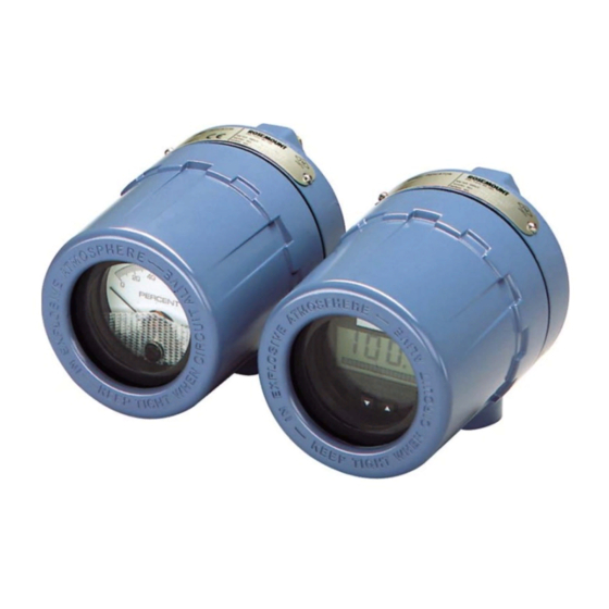
Индикаторы сигналов Rosemount 751 Field Signal позволяют отображать важные переменные процесса. Эти устройства работают с любым двухпроводным преобразователем, который измеряет
входные переменные, такие как давление, расход, уровень жидкости или температура. Индикаторы Rosemount идеально подходят для установок, в которых трудно установить встроенный расходомер. view.
Индикаторы Rosemount 751 предназначены для использования в промышленных условиях, где необходимы всепогодные характеристики. Эти агрегаты устойчивы к вибрации и коррозии,
взрывозащищенные или искробезопасные. ЖК-дисплей или аналоговый счетчик можно заказать для удовлетворения конкретных требований применения.
ЖК-дисплей 1.2
Для ЖК-дисплея требуется аналоговый выход постоянного тока 4–20 мА от двухпроводного преобразователя. Он может быть сконфигурирован от точки 4 мА от –999 до 1000 и точки 20 мА от -999 до 9999. Сумма точки 4 мА и диапазона не должна превышать 9999. Десятичная точка может быть помещена в любой из трех позиции (XXXX) или не используются. Калибровка выполняется с помощью неинтерактивных кнопок нуля и диапазона. Масштабированный измеритель может быть помечен соответствующими техническими единицами измерения. Гистограмма из двадцати сегментов в нижней части лицевой панели измерителя напрямую представляет сигнал 4–20 мА.
Большой 2¼ дюйма. На лицевой стороне измерителя нанесены символы высотой ½ дюйма для удобства чтения, как показано на рис. 1-1. Точки 4 и 20 мА можно изменить, нажав кнопки на лицевой панели измерителя. Измеритель можно поворачивать с шагом 90 градусов внутри корпуса для удобства. viewIng.
Рисунок 1-1: ЖК-дисплей
1.3 Сервисная поддержка
Чтобы ускорить процесс возврата, посетите веб-сайт Emerson.com и свяжитесь с ближайшим представителем Emerson.![]() ВНИМАНИЕ!
ВНИМАНИЕ!
Лица, работающие с продуктами, подвергшимися воздействию опасного вещества, могут избежать травм, если они проинформированы об опасности и понимают ее. Возвращаемые продукты должны включать копию паспорта безопасности (SDS) для каждого вещества.
Представители Emerson разъяснят дополнительную информацию и процедуры, необходимые для возврата товаров, подвергшихся воздействию опасных веществ.
1.4 Переработка/утилизация продукта
Подумайте о переработке оборудования и упаковки. Утилизируйте изделие и упаковку в соответствии с местным и национальным законодательством.
Установка
Ассамблея 2.1
Полевой индикатор сигналов Rosemount 751 состоит из компонентов, показанных на рис. 2-1. Корпус может содержать аналоговый дисплей или жидкокристаллический дисплей (ЖКД). Оба счетчика не зависят от составных частей и полностью взаимозаменяемы. Оба расходомера вставляются в клеммные винты на корпусе, как показано на рис. 2-1.
Подузел измерителя содержит компоненты, показанные на рисунках 2-2.
Рисунок 2-1: Rosemount 751 в разобранном виде View
| А. Клеммные винты B. Кольцевое уплотнение корпуса C. Клеммы полевой проводки D. Защитный диод контура E. Монтажная бобышка с резьбой F. Дополнительный монтажный кронштейн G. Крепежный болт с шайбой |
H. U-образный болт для 2-дюймового трубка I. Жилье J. Опционально от ¾ до ½ дюйма. переходная втулка кабелепровода (при необходимости) К. Метр Л. Бушинг M. Пенопластовая прокладка Н. Крышка корпуса |
Рисунок 2-2: Расходомер в разобранном виде View
| А. Фиксирующие ремни B. Крепление винтом к корпусу C. Шайба для удерживающего ремня D. Монтажные винты в монтажную пластину E. Винты клемм (2) |
F. Монтажная пластина G. Распорная пластина H. ЖК-дисплей I. Втулка J. Пенопластовая прокладка K. Кнопки конфигурации |
2.2 Схемы подключения
Используйте следующие схемы подключения для последовательного или параллельного подключения полевого индикатора сигналов Rosemount 751 к преобразователям Rosemount. Используйте экранированный кабель для достижения наилучших результатов в среде с электрическими помехами.
Конфигурация серии
Рекомендуется, чтобы индикатор Rosemount 751 подключался последовательно, когда преобразователь 4–20 мА не имеет тестовой клеммы. Индикатор разработан
таким образом, аналоговый измерительный прибор или измерительный прибор с ЖК-дисплеем можно извлечь из корпуса без нарушения целостности контура 4–20 мА. Удаление всего устройства из последовательной конфигурации приведет к нарушению контура.
Рис. 2-3. Схемы подключения Rosemount серии 751 для Rosemount 3144P и 2051.
Входной сигнал постоянного тока 4–20 мА для Rosemount 3144P
А. Электропитание
Б. Нагрузочный резистор
C. Дополнительное заземление
Входной сигнал 4–20 пост. тока для Rosemount 2051
Рис. 2-4. Схемы подключения Rosemount серии 751 для Rosemount 3051C и 3051S.
| Входной сигнал постоянного тока 4–20 мА для Rosemount 3144P | Входной сигнал 4–20 пост. тока для Rosemount 2051 |
Входной сигнал 4–20 мА постоянного тока для Rosemount 3051C
А. Электропитание
Б. Нагрузочный резистор
C. Дополнительное заземление
Входной сигнал 4–20 пост. тока для Rosemount 3051S
Параллельная конфигурация
Рекомендуется, чтобы устройство подключалось в параллельной конфигурации, когда преобразователь 4-20 мА имеет тестовую клемму. Использование тестового терминала требуется в параллельной конфигурации. Подключение индикатора к положительной и отрицательной клеммам преобразователя 4–20 мА может повлиять на контур.
Параллельная конфигурация позволит снять индикатор без нарушения целостности контура 4–20 мА. Кроме того, можно добавить запасные индикаторы, не прерывая цикл.
Рисунок 2-5: Схемы параллельного подключения Rosemount 751 для Rosemont 3144P и 2051
Входной сигнал 4–20 мА постоянного тока для Rosemount 3051C
А. Электропитание
Б. Нагрузочный резистор
C. Дополнительное заземление
Входной сигнал 4–20 пост. тока для Rosemount 3051S
Рисунок 2-6: Схемы параллельного подключения Rosemount 751 для Rosemount 3051C и 3051S
| Входной сигнал постоянного тока 4–20 мА для Rosemount 3144P | Входной сигнал 4–20 пост. тока для Rosemount 2051 |
Входной сигнал 4–20 мА постоянного тока для Rosemount 3051C
А. Электропитание
Б. Нагрузочный резистор
C. Дополнительное заземление
Входной сигнал 4–20 пост. тока для Rosemount 3051S
2.3 Конфигурация ЖК-дисплея
20-сегментная гистограмма откалибрована на заводе и напрямую представляет 4–20 мА, но конечные точки ЖК-дисплея задаются пользователем. Измерителю требуется ток от 4 до 20 мА для масштабирования, но фактическое значение тока не имеет значения.
2.3.1 Снимите крышку![]() ПРЕДУПРЕЖДЕНИЕ
ПРЕДУПРЕЖДЕНИЕ
Взрывы могут привести к смерти или серьезным травмам. Не снимайте крышку трансмиттера во взрывоопасных средах, когда цепь находится под напряжением.
Процедура
Отвинтите и снимите прозрачную крышку корпуса с корпуса ЖК-дисплея.
Внимание
Время ожидания ЖК-дисплея составляет примерно 16 секунд. Если вы не нажмете кнопки конфигурации в течение 16 секунд, индикатор вернется к показанию текущего
сигнал.
2.3.2 Установите десятичную точку и выберите функцию счетчика
Процедура
- Одновременно нажмите левую и правую кнопки конфигурации и сразу же отпустите их.
- Чтобы переместить десятичную точку в нужное место, нажмите левую кнопку конфигурации.
Внимание
Десятичная точка обтекает. - Для прокрутки вариантов режима нажимайте правую кнопку конфигурации несколько раз, пока измеритель не отобразит нужный режим (см. Таблицу 2-1).
Внимание
Время ожидания ЖК-дисплея составляет примерно 16 секунд. Если вы не нажмете кнопки конфигурации в течение 16 секунд, индикатор вернется к считыванию текущего сигнала.
Таблица 2-1: Параметры режима ЖК-дисплея
| Опции | Связь между входным сигналом и Цифровой индикатор |
| Лин | Линейные приводы |
| ЛинФ | Линейный с 5-секундным фильтром |
| Srt | Квадратный корень |
| SF | Квадратный корень с 5-секундным фильтром |
| Функция квадратного корня относится только к цифровому дисплею. Выход гистограммы остается линейным с текущим сигналом. |
Таблица 2-1: Параметры режима ЖК-дисплея (продолжение)
| Опции | Связь между входным сигналом и цифровым дисплеем |
| Ответ квадратного корня Цифровой дисплей будет пропорционален квадратному корню входного тока, где 4 мА = 0 и 20 мА = 1.0, масштабированному в соответствии с процедурой калибровки. Точка перехода от линейного к квадратному корню находится при 25 процентах полного расхода. |
|
| Ответ фильтра действует на «текущий вход» и «вход, полученный в предыдущем пятисекундном интервале» следующим образом: Дисплей = (0.75 предыдущего ввода) + (0.25 текущего ввода) Это соотношение сохраняется при условии, что предыдущее показание минус текущее показание составляет менее 25 процентов от полной шкалы. |
2.3.3 Хранение информации
Процедура
Нажмите обе кнопки конфигурации одновременно на две секунды.
Внимание
Прибор отображает «- -» в течение примерно 7.5 секунд, пока информация сохраняется.
2.3.4 Установите дисплей, эквивалентный сигналу 4 мА
Процедура
- Нажмите левую кнопку конфигурации на две секунды.
- Чтобы уменьшить отображаемые цифры, нажмите левую кнопку конфигурации. Чтобы увеличить число, нажмите правую кнопку конфигурации. Установите числа от –999 до 1000.
- Для сохранения информации одновременно нажмите обе кнопки конфигурации на две секунды.
2.3.5 Установите дисплей, эквивалентный сигналу 20 мА
Процедура
- Нажмите правую кнопку конфигурации на две секунды.
- Чтобы уменьшить отображаемые цифры, нажмите левую кнопку конфигурации. Чтобы увеличить число, нажмите правую кнопку конфигурации. Установите числа от –999 до 9999.
Внимание
Сумма точки 4 мА и диапазона не должна превышать 9999. - Для сохранения информации одновременно нажмите обе кнопки конфигурации на две секунды. Индикатор ЖК-дисплея теперь настроен.
2.3.6 Установите крышку
Процедура
Убедитесь, что резиновая прокладка установлена правильно, и навинтите прозрачную крышку корпуса на корпус измерителя с ЖК-дисплеем.
Информация для заказа, спецификации и чертежи
к view актуальную информацию для заказа Rosemount 751, технические характеристики и чертежи, выполните следующие действия:
Процедура
- Перейдите на сайт Emerson.com/Rosemount/Rosemount 751 Field Signal Indicator.
- При необходимости прокрутите до зеленой строки меню и нажмите «Документы и рисунки».
- Для установочных чертежей нажмите «Чертежи и схемы» и выберите соответствующий документ.
- Для получения информации о заказе, спецификаций и габаритных чертежей нажмите «Технические паспорта и бюллетени» и выберите соответствующий паспорт продукта.
- Для Декларации о соответствии щелкните Сертификаты и разрешения и выберите самый последний документ.
Для получения дополнительной информации: www.emerson.com
© 2022 Эмерсон. Все права защищены.
Условия продажи Emerson доступны по запросу. Логотип Emerson является товарным знаком и знаком обслуживания
Emerson Electric Co. Rosemount является торговой маркой одного из
Группа компаний Emerson. Все остальные товарные знаки являются собственностью их соответствующих владельцев.
Документы / Ресурсы
Рекомендации
- Manuals
- Brands
- Emerson Manuals
- Touch Panel
- Rosemount 751
Manuals and User Guides for Emerson Rosemount 751. We have 3 Emerson Rosemount 751 manuals available for free PDF download: Quick Start Manual, Reference Manual
Emerson Rosemount 751 Quick Start Manual (20 pages)
Field Signal Indicator
Brand: Emerson
|
Category: Touch Panel
|
Size: 2.25 MB
Table of Contents
-
Installation
3
-
Wiring Diagrams
5
-
LCD Display Configuration
9
-
Remove the Cover
9
-
Position the Decimal Point and Select the Meter Function
9
-
Store the Information
10
-
Set the Display Equivalent to a 4 Ma Signal
10
-
Set the Display Equivalent to a 20 Ma Signal
10
-
Replace the Cover
10
-
Product Certifications
11
-
European Directive Information
11
-
Ordinary Location Certification
11
-
Installing Equipment in North America
11
Advertisement
Emerson Rosemount 751 Quick Start Manual (24 pages)
Field Signal Indicator
Brand: Emerson
|
Category: Measuring Instruments
|
Size: 1.93 MB
Table of Contents
-
Table of Contents
2
-
Installation
3
-
Configuration
9
-
Product Certification
12
-
February
14
-
Declaration of Conformity
18
-
China Rohs
21
-
Rosemount
22

Emerson Rosemount 751 Reference Manual (18 pages)
Field Signal Indicator
Brand: Emerson
|
Category: Industrial Equipment
|
Size: 0.78 MB
Table of Contents
-
Table of Contents
3
-
Chapter 1 Introduction
5
-
Product Overview
5
-
LCD Display
5
-
Service Support
6
-
Product Recycling/Disposal
6
-
-
Chapter 2 Installation
7
-
Assembly
7
-
Wiring Diagrams
8
-
LCD Display Configuration
12
-
Ordering Information, Specifications, and Drawings
17
-
Advertisement
Advertisement
Related Products
-
Emerson Rosemount 752
-
Emerson Rosemount 752 FOUNDATION
-
Emerson 755A
-
Emerson Daniel 750
-
Emerson Daniel 754
-
Emerson Rosemount 753R
-
Emerson 700W
-
Emerson Keystone Figure 79E-006S
-
Emerson NetSure 721NPBB
-
Emerson 781 Field Link
Emerson Categories
Controller
Control Unit
Transmitter
Measuring Instruments
Fan
More Emerson Manuals
Технические характеристики
- Материалы конструкции
- Корпус: алюминий с низким содержанием меди; Краска: полиуретан; Уплотнительные кольца: Buna N; Крепежные материалы: полифениленоксид GE
- Класс защиты корпуса
- NEMA тип 4x. CSA тип 4x. IP66
- Сертификация
- Опасные зоны, морское применение, полный перечень сертификатов доступен в листе технических данных
Особенности
- Отображает важные параметры процесса для установок с затрудненным доступом к измерительным приборам
- Работает с любым двухпроводным измерительным преобразователем давления, расхода, уровня жидкости или температуры, обеспечивая гибкость применения
- Возможность выбора исполнения с ЖКИ или стрелочным аналоговым индикатором в зависимости от требований применения
- Лицевая панель прибора 2,25 дюйма в диаметре, снабжена 2-дюймовой шкалой, обеспечивающей лёгкость считывания данных.
- Для удобства обзора индикатор может быть повернут внутри корпуса с шагом 90 градусов.
- Компактная, прочная конструкция обеспечивает вибрационную и коррозионную стойкость, помогающую выдерживать жесткие промышленные условия
- Разрешения международных организаций на применение в опасных зонах
- Аналогичные товары
Вся информация на сайте о товарах и ценах носит справочный характер и не является публичной офертой. Производитель оставляет за собой право изменять характеристики товара, его внешний вид и комплектность без предварительного уведомления продавца
 Loading…

Reference Manual
00809-0100-4378, Rev CE
February 2014
Rosemount 751 Field Signal Indicator

|
Reference Manual |
Title Page |
|
00809-0100-4378, Rev CE |
February 2014 |
Rosemount 751 Field Signal Indicator
NOTICE
Read this manual before working with the product. For personal and system safety, and for optimum product performance, make sure you thoroughly understand the contents before installing, using, or maintaining this product.
Within the United States, Rosemount Inc. has two toll-free assistance numbers:
Customer Central
Technical support, quoting, and order-related questions. 1-800-999-9307 (7:00 am to 7:00 pm CST)
North American Response Center Equipment service needs.
1-800-654-7768 (24 hours—includes Canada)
Outside of the United States, contact your local Emerson Process Management representative.
The products described in this document are NOT designed for nuclear-qualified applications. Using non-nuclear qualified products in applications that require nuclear-qualified hardware or products may cause inaccurate readings.
For information on Rosemount nuclear-qualified products, contact your local Emerson Process Management Sales Representative.
1

|
Reference Manual |
Table of Contents |
|
00809-0100-4378, Rev CE |
February 2014 |
Section 1: Introduction
1.1 LCD display . . . . . . . . . . . . . . . . . . . . . . . . . . . . . . . . . . . . . . . . . . . . . . . . . . . . . . . . . . . .3 1.2 Analog meter . . . . . . . . . . . . . . . . . . . . . . . . . . . . . . . . . . . . . . . . . . . . . . . . . . . . . . . . . .4 1.3 Service support. . . . . . . . . . . . . . . . . . . . . . . . . . . . . . . . . . . . . . . . . . . . . . . . . . . . . . . . .5 1.4 Product recycling/disposal . . . . . . . . . . . . . . . . . . . . . . . . . . . . . . . . . . . . . . . . . . . . . . .5
Section 2: Installation
2.1 Assembly . . . . . . . . . . . . . . . . . . . . . . . . . . . . . . . . . . . . . . . . . . . . . . . . . . . . . . . . . . . . . .7 2.2 Wiring diagrams . . . . . . . . . . . . . . . . . . . . . . . . . . . . . . . . . . . . . . . . . . . . . . . . . . . . . . . .9 2.3 LCD display configuration. . . . . . . . . . . . . . . . . . . . . . . . . . . . . . . . . . . . . . . . . . . . . . .11 2.3.1 Remove the cover. . . . . . . . . . . . . . . . . . . . . . . . . . . . . . . . . . . . . . . . . . . . . . . .11 2.3.2 Position the decimal point and select the meter function . . . . . . . . . . . . .11 2.3.3 Store the information . . . . . . . . . . . . . . . . . . . . . . . . . . . . . . . . . . . . . . . . . . . .12 2.3.4 Set the display equivalent to a 4 mA signal . . . . . . . . . . . . . . . . . . . . . . . . . .12 2.3.5 Set the display equivalent to a 20 mA signal . . . . . . . . . . . . . . . . . . . . . . . . .12 2.3.6 Replace the cover . . . . . . . . . . . . . . . . . . . . . . . . . . . . . . . . . . . . . . . . . . . . . . . .12
Appendix A: Reference data
A.1 Housing specifications . . . . . . . . . . . . . . . . . . . . . . . . . . . . . . . . . . . . . . . . . . . . . . . . .13
A.1.1 Physical specifications . . . . . . . . . . . . . . . . . . . . . . . . . . . . . . . . . . . . . . . . . . . .13
A.2 LCD display specifications. . . . . . . . . . . . . . . . . . . . . . . . . . . . . . . . . . . . . . . . . . . . . . .14
A.2.1 Functional specifications. . . . . . . . . . . . . . . . . . . . . . . . . . . . . . . . . . . . . . . . . .14
A.2.2 Performance specifications. . . . . . . . . . . . . . . . . . . . . . . . . . . . . . . . . . . . . . . .15
A.2.3 Physical specification . . . . . . . . . . . . . . . . . . . . . . . . . . . . . . . . . . . . . . . . . . . . .15
A.3 Analog meter specifications. . . . . . . . . . . . . . . . . . . . . . . . . . . . . . . . . . . . . . . . . . . . .16
A.3.1 Functional specifications. . . . . . . . . . . . . . . . . . . . . . . . . . . . . . . . . . . . . . . . . .16
A.3.2 Performance specifications. . . . . . . . . . . . . . . . . . . . . . . . . . . . . . . . . . . . . . . .16
A.3.3 Physical specification . . . . . . . . . . . . . . . . . . . . . . . . . . . . . . . . . . . . . . . . . . . . .16
A.4 Dimensional drawings. . . . . . . . . . . . . . . . . . . . . . . . . . . . . . . . . . . . . . . . . . . . . . . . . .17
A.5 Ordering information . . . . . . . . . . . . . . . . . . . . . . . . . . . . . . . . . . . . . . . . . . . . . . . . . .18
Appendix B: Product Certifications
B.1 European directive information. . . . . . . . . . . . . . . . . . . . . . . . . . . . . . . . . . . . . . . . . .21
B.2 Ordinary location certification for FM approvals . . . . . . . . . . . . . . . . . . . . . . . . . . .21
B.2.1 North America. . . . . . . . . . . . . . . . . . . . . . . . . . . . . . . . . . . . . . . . . . . . . . . . . . .21
B.2.2 . . . . . . . . . . . . . . . . . . . . . . . . . . . . . . . . . . . . . . . . . . . . . . . . . . . . . . . . . Europe22
B.2.3 International . . . . . . . . . . . . . . . . . . . . . . . . . . . . . . . . . . . . . . . . . . . . . . . . . . . .22
Appendix C: Approval drawings
|
C.1 Declaration of conformity . . . . . . . . . . . . . . . . . . . . . . . . . . . . . . . . . . . . . . . . . . . . . . |
34 |
|
|
Table of Contents |
1 |

|
Reference Manual |
Section 1: Introduction |
|
00809-0100-4378, Rev CE |
February 2014 |
Section 1 Introduction
LCD display . . . . . . . . . . . . . . . . . . . . . . . . . . . . . . . . . . . . . . . . . . . . . . . . . . . . . . . . . . . . . . . . . page 3 Analog meter . . . . . . . . . . . . . . . . . . . . . . . . . . . . . . . . . . . . . . . . . . . . . . . . . . . . . . . . . . . . . . . page 4 Service support . . . . . . . . . . . . . . . . . . . . . . . . . . . . . . . . . . . . . . . . . . . . . . . . . . . . . . . . . . . . . page 5 Product recycling/disposal . . . . . . . . . . . . . . . . . . . . . . . . . . . . . . . . . . . . . . . . . . . . . . . . . . . page 5
The Rosemount 751 Field Signal Indicators provide a means of displaying important process variables. These devices operate with any two-wire transmitter that measures input variables such as pressure, flow, liquid level, or temperature. Rosemount indicators are ideal for installations where an integral meter would be difficult to view.
Rosemount 751 Indicators are designed for use in industrial environments where all-weather performance is necessary. These units are vibrationand corrosion-resistant, and explo- sion-proof or intrinsically safe. An LCD display or analog meter may be ordered to meet specific application requirements.
1.1LCD display
The LCD display requires an analog 4–20 mA dc output from a two-wire transmitter. It may be configured from a 4 mA point of –999 to 1000 and a 20 mA point of -999 to 9999. The sum of the 4 mA point and the span must not exceed 9999. The decimal point can be placed in any of three positions (X.X.X.X) or not used. Calibration adjustments are made using noninteractive zero and span buttons. The scaled meter may be labelled with the appropriate engineering units. A twenty-segment bar graph, on the bottom of the meter faceplate, represents the 4–20 mA signal directly.
The large 21/4-inch meter face has 1/2-inch-high characters for easy readability as shown in Figure 1-1. The 4 and 20 mA points may be changed by pressing the buttons on the meter faceplate. The meter can be rotated in 90-degree increments within the enclosure for convenient viewing.
Figure 1-1. LCD display
LCD display

|
Section 1: Introduction |
Reference Manual |
|
February 2014 |
00809-0100-4378, Rev CE |
1.2Analog meter
The analog meter requires an analog 4–20 mA dc, 10–50 mA dc, or 40–200 mV dc transmitter output from a two-wire transmitter. Several meter calibration options are available to suit the requirements of a particular application. Linear 0 to 100 percent meter scaling is adequate for the majority of applications. A logarithmic 0 to 100 percent scale is available for use with flow transmitters. As an option, the user can specify special meter scaling for direct readout in psi, gph, °F, °C, or other convenient engineering units.
The large 21/4-inch diameter meter face has a two-inch long scale for easy readability as shown in Figure 1-2. A meter-zero adjustment is located on the meter faceplate. The meter can be rotated in 90° increments within the enclosure for convenient viewing.
Figure 1-2. Analog Meter
Analog Meter Face

|
Reference Manual |
Section 1: Introduction |
|
00809-0100-4378, Rev CE |
February 2014 |
1.3Service support
To expedite the return process outside of the United States, contact the nearest Emerson Process Management representative.
Within the United States, call the Emerson Process Management Instrument and Valves Response Center using the 1-800-654-RSMT (7768) toll-free number. This center, available 24 hours a day, will assist you with any needed information or materials.
The center will ask for product model and serial numbers, and will provide a Return Material Authorization (RMA) number. The center will also ask for the process material to which the product was last exposed.
Individuals who handle products exposed to a hazardous substance can avoid injury if they are informed of and understand the hazard. If the product being returned was exposed to a hazardous substance as defined by OSHA, a copy of the required Material Safety Data Sheet (MSDS) for each hazardous substance identified must be included with the returned goods.
Emerson Process Management Instrument and Valves Response Center representatives will explain the additional information and procedures necessary to return goods exposed to hazardous substances.
1.4Product recycling/disposal
Recycling of equipment and packaging should be taken into consideration and disposed of in accordance with local and national legislation/regulations.
![]()
|
Reference Manual |
Section 2: Installation |
|
00809-0100-4378, Rev CE |
February 2014 |
Section 2 Installation
Assembly . . . . . . . . . . . . . . . . . . . . . . . . . . . . . . . . . . . . . . . . . . . . . . . . . . . . . . . . . . . . . . . . . . page 7 Wiring diagrams . . . . . . . . . . . . . . . . . . . . . . . . . . . . . . . . . . . . . . . . . . . . . . . . . . . . . . . . . . . . page 9 LCD display configuration . . . . . . . . . . . . . . . . . . . . . . . . . . . . . . . . . . . . . . . . . . . . . . . . . . . . page 11
2.1Assembly
The Rosemount 751 Field Signal Indicator is comprised of the components shown in Figure 2-1. The housing may contain an analog or LCD display. Both meters are independent of component parts and are completely interchangeable. Both meters plug into the terminal screws on the housing, as shown in Figure 2-1.
The meter subassembly contains the components shown in Figure 2-2.
Figure 2-1. Rosemount 751 Exploded View
|
F |
||
|
G |
||
|
D |
E |
|
|
C |
H |
|
|
B |
||
|
A |
||
|
I |
||
|
K |
J |
|
|
M |
L |
|
|
N |
||
|
A. Terminal Screws |
H. U-Bolt for 2-inch Pipe |
|
|
B. Housing O-Ring |
I. Housing |
|
|
C. Field Wiring Terminals |
J. Optional ¾ to ½-inch Conduit Reducing Bushing (if required) |
|
|
D. Loop Protection Diode |
K. Meter |
|
|
E. Tapped Mounting Boss |
L. Bushing |
|
|
F. Optional Mounting Bracket |
M. Foam Spacer |
|
|
G. Mounting Bolt with Washer |
N. Housing Cover |

|
Section 2: Installation |
Reference Manual |
|
|
February 2014 |
00809-0100-4378, Rev CE |
|
Figure 2-2. LCD display exploded view
B
C
A
D
G

 H
H
I
 J
J
A.Retaining Straps
B.Mounting Screw into Housing
C.Washer for Retaining Strap
D.Mounting Screws into Mounting Plate
E.Terminal Screws (2)
F.Mounting Plate
G.Spacer Plate
H.LCD Display
I.Bushing
J.Foam Spacer
K.Configuration Buttons

|
Reference Manual |
Section 2: Installation |
|
00809-0100-4378, Rev CE |
February 2014 |
2.2Wiring diagrams
Use the following wiring diagrams to wire the Rosemount 751 Field Signal Indicator, in series or in parallel, with Rosemount transmitters. Use shielded cable for best results in electrically noisy environments.
It is recommended that the 751 indicator be wired in a series configuration when the 4-20 mA transmitter does not contain a test terminal. The 751 is designed so the analog or LCD display can be removed from the housing without impacting the integrity of the 4-20 mA loop.
Removal of the entire 751 device from the series configuration will disrupt the loop.
Figure 2-3. Rosemount 751 Series Wiring Diagrams
Series Wiring Diagrams for Rosemount 3144P Temperature transmitters and Rosemount 2051, 3051C, or 3051S Pressure Transmitters
Power Supply
|
+ – |
Load Resistor |
|
3144P |
Optional Ground |
 –
–
+
 T
T
4–20 mA dc Input Signal for Rosemount 3144P
Power Supply
|
+ – |
Load Resistor |
||
|
3051C |
Optional Ground |
||
|
+ |
– |
T |
|
|
751 |
|||
|
– |
+ |
4–20 mA dc Input Signal for Rosemount 3051C
Power Supply
|
+ – |
Load Resistor |
||
|
2051 |
Optional Ground |
||
|
+ |
– |
T |
|
|
751 |
|||
|
– |
+ |
4–20 dc Input Signal for Rosemount 2051
|
Power Supply |
||
|
+ – |
Load Resistor |
|
|
3051S |
Optional Ground |
|
|
+ |
– |
T |
|
751 |
||
|
– |
+ |
4–20 dc Input Signal for Rosemount 3051S