-
Contents
-
Table of Contents
-
Bookmarks
Quick Links
Installation and user’s guide
H-2000-5219-01-A
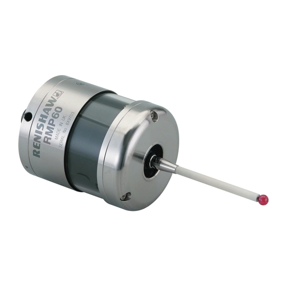
RMP60 — radio probe
Related Manuals for Renishaw RMP60
Summary of Contents for Renishaw RMP60
-
Page 1
Installation and user’s guide H-2000-5219-01-A RMP60 — radio probe… -
Page 2
The publication of material within this document does not imply freedom Trademarks from the patent rights of Renishaw plc. All brand names and product names used in this document are trade names, service marks, trademarks, or registered trademarks of their respective owners. -
Page 3
Emissions to class A (non-domestic) limits. and that it complies with the requirements of directive (as amended): — 89/336/EEC — Electromagnetic compatibility The above information is summarised from the full EC declaration of conformity. A copy is available from Renishaw on request. -
Page 4
Keep system components clean and treat the must be returned to your supplier. No claims probe as a precision tool. will be considered where Renishaw equipment Patent notice has been misused, or repairs or adjustments have been attempted by unauthorised persons. -
Page 5: Table Of Contents
Contents Contents Typical probe system with radio RMP60 batteries ……….. 17 transmission ………… 4 Battery life expectancy ……… 19 System performance ……..5 RMP60/shank mounting ……. 21 Operating envelope ……… 6 Stylus on-centre adjustment ……22 RMP60 features ……….7 Stylus trigger force adjustment …..
-
Page 6: Typical Probe System With Radio Transmission
Typical probe system with radio transmission Typical probe system with radio transmission CNC machining centre spindle Interface mounting bracket RMP60 C N C inspection probe machine control Optional — PSU3 power supply unit Probe status LEDs Typical tool setting probe…
-
Page 7: System Performance
RMP60 signal transmission range. Temperature PSU3 Coolant and swarf residue accumulating on the RMP60 and RMI may have a detrimental effect -10 °C to 70 °C Storage on transmission performance. Wipe clean as (14 °F to 158 °F) often as is necessary to maintain unrestricted 5 °C to 50 °C…
-
Page 8: Operating Envelope
Operating envelope Operating envelope Range metres (feet) RMP60 probe + RMI OPERATING AND SWITCH ON/OFF RMP60 and RMI must be within each others 75° 15 (49) operating envelope shown. 60° 90° 75° 75° 10 (33) 60° 60° 45° 45° 45°…
-
Page 9: Rmp60 Features
RMP60 features RMP60 features Dimensions mm (in) 50 (1.97) 19 (0.75) A range of probe ready shanks is available from RMP60 window Renishaw upon request M4 stylus 18° 18° Battery cover Ø63 (Ø2.48) 76 (2.99) STYLUS OVERTRAVEL LIMITS Stylus length ±X / ±Y…
-
Page 10: Rmp60 Specification
Z direction 4.90 N / 490 gf green operating mode (17.28 ozf) and blue — low battery Flashing Probe triggered in RMP60 IP rating IPX8 red and operating mode blue — low battery RMP60 weight Without batteries (without shank) 855 g (30.16 oz)
-
Page 11: Probe Status Led
X / Y Weak link (steel styli only) 18° 18° Fitting stylus with weak Removing a broken Fitting a weak link link onto RMP60 weak link In the event of 2 Nm (1.7 lbf.ft) excessive stylus 5 mm AF overtravel the weak 2 Nm (1.7 lbf.ft)
-
Page 12: Modes Of Operation
Modes of operation Modes of operation RMP60 switch-on RMP60 power on/off The RMP60 probe can be in one of three modes: Switch-on options are configurable 1. Stand-by mode — The RMP60 is waiting for — see page 13. a switch-on signal .
-
Page 13
2. Timer off (time out) Note: (Only applies when radio on/spin on After being turned on, the RMP60 must be mode is selected). on for a minimum of 1 sec (7 sec for spin The RMP60 will time out (12, 33 or off) before being turned off. -
Page 14: Reviewing Current Probe Settings
Reviewing current probe settings Reviewing current probe settings START Note This menu will be omitted if shank Batteries removed from probe turn on has been selected Insert batteries: note the LED sequence, which follows the form below SWITCH OFF METHOD setting Short Medium Long…
-
Page 15: Configuration Using Trigger Logic
Configuration using trigger logic Configuration using trigger logic START Note This menu will be omitted if shank Remove batteries from probe. turn on has been selected Hold stylus deflected and insert batteries. Release the stylus only after 15 seconds. SWITCH OFF METHOD menu The current probe settings review Deflect the stylus (>0.5 sec) to sequence, detailed on page 12 will…
-
Page 16
Settings record table ACQUISITION MODE ACQUISITION MODE Switch on Radio method Shank Once configuration is complete, leave the RMP60 in triggered for 20 sec to save Spin configuration and go to stand-by. Radio/spin Switch off method Return to Short time out… -
Page 17: System Setup/Establishing Rmp60/Rmi Partnership
6. RMI pattern will change to red & yellow configuration using trigger logic. flashing when it acquires the RMP. 1. Use trigger logic to set RMP60 turn on/ off 7. Allow ~10 seconds for both RMP60 and modes as desired.
-
Page 18
RMI to be partners with more than one RMP60. It is possible for an RMP60 to be partners with more than one RMI, but the system will not work correctly if more than one partner RMI is… -
Page 19: Rmp60 Batteries
Only use specified batteries. Do not mix new and used batteries or battery types, as this will result in reduced life and Clean and dry RMP60 with a cloth or paper towel damage to the batteries. before removing battery cover. Where the…
-
Page 20
RMP60 batteries Battery cover Batteries 2 x AA DO NOT leave exhausted batteries in probe Please dispose of exhausted batteries DO NOT allow coolant or debris to enter the in accordance with local regulations. battery compartment Do not dispose of batteries in fire. -
Page 21: Battery Life Expectancy
(page 12). typically the probe will continue to operate for In order to achieve stated radio stand-by life, approximately 2 weeks after a low battery the RMP60 must be in range of powered warning is first indicated. partner RMI. CONTINUOUS…
-
Page 22
Part number will change to constant red. 596-602, 201-9438, Radio Shack 23-037 Battery specification The RMP60 requires two identical AA size Manufacturer Part number batteries, individually rated at a voltage of Saft LS 14500 between 1.2 V and 3.6 V. -
Page 23: Rmp60/Shank Mounting
6. Tighten screws B to 6-8 Nm (4.4- 5.9 lb.ft) (Partially tighten screws B to 2 — 3 Nm (1.47 — 2.2 lbf.ft), if RMP60 is to be on-centre adjusted). 7. The RMP60 assembly is ready for use.
-
Page 24: Stylus On-Centre Adjustment
20 µm, fully tighten screws B to 6 — 8 Nm (4.4 — 5.9 lbf.ft). 10. For final centering use screws A to move the RMP60, progressively slackening on one side and tightening the opposite screw, as the final setting is approached, using two hexagon keys.
-
Page 25: Stylus Trigger Force Adjustment
Spring force within the probe causes the stylus to sit in one unique position, and return to this position following each stylus deflection. Stylus trigger force is set by Renishaw. The user should only adjust trigger force in special circumstances e.g. excessive machine vibration or insufficient force to support the stylus weight.
-
Page 26: Probe Moves
Probe moves Probe moves Probe trigger With a double touch sequence the first move finds the surface quickly. Then the probe is backed off A probe trigger signal is generated when the to a position clear of the surface, before making probe’s stylus is driven against a surface.
-
Page 27
Probe interface signals 1. Error signal delay Probing cycles are available from Renishaw A delay of 28 ms maximum for the RMI, will elapse between an error occurring and the Calibrating a system output indicating error. -
Page 28: Software Requirements
Software requirements Software requirements Verify your software Probing cycles and features are machine Does your software have suitable calibration software dependant. Good software will allow the routines which compensate for stylus on-centre following functions : errors? If not, you must set the probe stylus on-centre mechanically.
-
Page 29: Typical Probe Cycles
Typical probe cycles for machining centres Typical probe cycles for machining centres Simple to use canned cycles for basic features Inspection probe Inspection calibration Bore and boss measure Probe XY offset calibration Web and pocket measure Stylus ball radius calibration Internal and external corner find Probe length calibration…
-
Page 30
Bore and boss on PCD 4th axis measure Angled web and pocket measure Feature-to-feature measure Angled surface measure Macro software for use with the RMP60 is available from Renishaw for the majority of major controller types, please see Parts list (page 39). -
Page 31: Diaphragm Replacement
Diaphragm replacement Diaphragm replacement RMP60 DIAPHRAGMS OUTER DIAPHRAGM INSPECTION The probe mechanism is protected 1. Remove the stylus. from coolant and debris by two diaphragms. 2. Undo three M3 front cover screws These provide adequate protection under and remove the front cover normal working conditions.
-
Page 32
Diaphragm replacement OUTER DIAPHRAGM REPLACEMENT 6. Fit new diaphragm over centre. M3 screw 7. Locate outer edge of diaphragm to rest 2.5 mm AF on outer edge of inner diaphragm. 1 Nm (0.74 lbf.ft) 8. Refit front cover and M3 screws. 9. -
Page 33: Fault Finding
Fault-finding Fault finding — If in doubt, consult your probe supplier. Symptom Cause Action RMP60 fails to switch on Dead batteries Change batteries Batteries incorrectly Check/change batteries inserted Probe out of range Check position of RMI, see (does not apply to spin-on performance envelope.
-
Page 34
Fault-finding Symptom Cause Action RMP60 fails to switch off Incorrect switch off method Check configuration and alter configured. as required. No RMI ‘start/stop’ signal Check for green start LED (applicable only in radio off, Check wiring. mode, but not applicable in Heidenhain mode). -
Page 35
Review program. path. No LED’s lit on RMI No power to RMI Check wiring RMI status LED’s do not Radio link failure – RMP60 Check position of RMI, correspond to RMP60 out of RMI range. see performance envelope. status LED’s… -
Page 36
Fault-finding Symptom Cause Action RMI error LED lit during Probe timed out Change setting. probing cycle (continued) Review turn off method Probe out of range Check position of RMI, see performance envelope. RMI error LED illuminated Probe not switched on. Check configuration and alter during intended probe cycle as required… -
Page 37
Fault-finding Symptom Cause Action Poor measurement Debris on part or stylus. Clean. results. Recalibrate if probe was calibrated with debris on stylus. Repeatability of probe Verify by repeated toolchange into spindle. and single point move. Loose probe to shank Check and tighten as mounting or stylus. -
Page 38: Appendix 1 Rmi
Appendix 1 Appendix 1 RMI (RADIO MACHINE INTERFACE) The RMI is fully described in User’s guide H-2000-5220 A visual indication of system status is provided by light emitting diodes (LED’s). Status is continuously updated and indication is provided for START, LOW BATTERY, PROBE STATUS, ERROR, SIGNAL STRENGTH LED LIGHT SIGNALS 1.
-
Page 39
Appendix 1 3. Error Notes. Error, other outputs may 1. The probe status LED will always be be incorrect. illuminated when power is present, there is no power present LED/light. Off: No Error. 2. All the indicators report the status of the 4. -
Page 40: Parts List
Please quote the Part no. when ordering equipment. Type Part no. Description RMP60 A-4113-0001 RMP60 probe with batteries, tool kit and User’s guide (set to radio on/radio off). RMP60 A-4113-0002 RMP60 probe with batteries, tool kit and User’s guide (set to radio on/time off).
-
Page 41
— For complete listing please see Renishaw Styli guide. Part no. H-1000-3200. Software — For complete list of Renishaw software for machine tools please see Data sheet. Part no. H-2000-2289. Shanks — For complete listing please see Renishaw Data sheet… -
Page 42
Renishaw plc +44 (0)1453 524524 New Mills, Wotton-under-Edge, +44 (0)1453 524901 Gloucestershire, GL12 8JR uk@renishaw.com United Kingdom www.renishaw.com For worldwide contact details, please visit our main website at www.renishaw.com/contact *H-2000-5219-01-A*…
Скачать
Installation and user’s guide
H-2000-5219-01-A
RMP60 — radio probe
 Loading…
![]()
Installation and user’s guide
H-2000-5219-01-A
RMP60 — radio probe
© 2003 Renishaw. All rights reserved.
Renishaw® is a registered trademark of Renishaw plc.
This document may not be copied or reproduced in whole or in part, or transferred to any other media or
language, by any means, without the prior written permission of Renishaw.
The publication of material within this document does not imply freedom from the patent rights of Renishaw plc.
Renishaw Part no: H-2000-5219-01-A
Issued: 08.2003
Disclaimer
Considerable effort has been made to ensure that the contents of this document are free from inaccuracies and omissions. However, Renishaw makes no warranties with respect to the contents of this document and specifically disclaims any implied warranties. Renishaw reserves the right to make changes to this document and to the product described herein without obligation to notify any person of such changes.
Trademarks
All brand names and product names used in this document are trade names, service marks, trademarks, or registered trademarks of their respective owners.

1
EC DECLARATION OF CONFORMITY
Renishaw plc declare that the product: —
Name: RMP60
Description: Radio machine probe
has been manufactured in conformity with the following standard: —
BS EN 61326:1998/ Electrical equipment for measurement, control and laboratory use — EMC requirements.
Immunity to annex A — industrial locations. Emissions to class A (non-domestic) limits.
and that it complies with the requirements of directive (as amended): —
|
89/336/EEC |
— Electromagnetic compatibility |
The above information is summarised from the full EC declaration of conformity. A copy is available from Renishaw on request.
|
2 |
Installation and user’s guide |
Installation and user’s guide
Warranty
Equipment requiring attention under warranty must be returned to your supplier. No claims will be considered where Renishaw equipment has been misused, or repairs or adjustments have been attempted by unauthorised persons.
Changes to equipment
Renishaw reserves the right to change specifications without notice.
CNC machine
CNC machine tools must always be operated by competent persons in accordance with manufacturers instructions.
Care of the probe
Keep system components clean and treat the probe as a precision tool.
Patent notice
Features of products shown in this guide, and of related products, are the subject of the following patents and/or patent applications:
EP 0652413
US 4599524
US 5,279,042
JP 3,126,797
WO 02/063235
WO 03/021182

Contents 3
|
Contents |
|
|
Typical probe system with radio |
|
|
transmission ……………………………………………. |
4 |
|
System performance ……………………………….. |
5 |
|
Operating envelope ………………………………….. |
6 |
|
RMP60 features ………………………………………. |
7 |
|
RMP60 specification ………………………………… |
8 |
|
Probe status LED …………………………………….. |
9 |
|
Weak link stem ………………………………………… |
9 |
|
Modes of operation ………………………………… |
10 |
|
Reviewing current probe settings ……………. |
12 |
|
Configuration using trigger logic ………………. |
13 |
|
System setup/establishing |
|
|
RMP60/RMI partnership …………………………. |
15 |
|
RMP60 batteries ……………………………………. |
17 |
|
Battery life expectancy …………………………… |
19 |
|
RMP60/shank mounting …………………………. |
21 |
|
Stylus on-centre adjustment ……………………. |
22 |
|
Stylus trigger force adjustment ………………… |
23 |
|
Probe moves …………………………………………. |
24 |
|
Software requirements ……………………………. |
26 |
|
Typical probe cycles ………………………………. |
27 |
|
Diaphragm replacement ………………………….. |
29 |
|
Fault finding ……………………………………………. |
31 |
|
Appendix 1 RMI ……………………………………. |
36 |
|
Parts list ………………………………………………… |
38 |
|
4 |
Typical probe system with radio transmission |
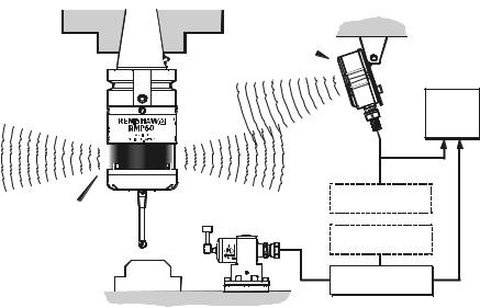
Typical probe system with radio transmission
CNC machining centre spindle
RMI
Interface
RMP60 inspectionprobe
|
Probe status LEDs |
Typical tool setting probe |
Stylus
Cable
RMI mounting bracket
C N C machine control
Optional — PSU3 power supply unit
Optional — PSU3 power supply unit
A workpiece set-up and inspection probe is in effect another tool in the system.
A probing cycle may be included at any stage of the machining process.
Probe data signals are transmitted via radio link to the RMI and on to the machine control. The RMI converts probe signals into an acceptable form for the machine control.
System performance
Operating envelope
Surfaces within the machine may increase the signal transmission range.
Coolant and swarf residue accumulating on the RMP60 and RMI may have a detrimental effect on transmission performance. Wipe clean as often as is necessary to maintain unrestricted transmission.
When operating, do not touch with your hand, either the RMI cover or the probe glass window, as this will change the performance.
Operation in extremes of temperature will result in some reduction in range.
RMI position
To assist finding the optimum position of the RMI during system installation, a signal strength indication LED is available on the RMI interface.
RMI signal strength is displayed on an RMI multi-coloured LED.
Environment
|
RMP60 |
Temperature |
|
|
RMI |
||
|
PSU3 |
||
|
Storage |
-10 °C to 70 °C |
|
|
(14 °F to 158 °F) |
||
|
Normal |
5 °C to 50 °C |
|
|
operating |
(41 F° to 122 °F) |
|
Probe repeatability
Maximum 2 Sigma (28) Value
Repeatability of 1,0 µm (40 µ in) is valid for test velocity of 480 mm/min (1.57 ft/min) at stylus tip, using stylus 50 mm (1.97 in) long.

6 Operating envelope
Operating envelope
|
RMP60 probe + RMI |
Range metres (feet) |
||||||||
|
OPERATING AND SWITCH ON/OFF |
|||||||||
|
RMP60 and RMI must be within each others |
|||||||||
|
operating envelope shown. |
75° |
15 (49) |
|||||||
|
75° |
90° |
75° |
60° |
||||||
|
10 (33) |
|||||||||
|
60° |
60° |
||||||||
|
45° |
45° |
||||||||
|
45° |
5 (16) |
||||||||
|
30° |
30° |
||||||||
|
15° |
15° |
||||||||
|
0° |
0° |
5 |
|||||||
|
(16) |
|||||||||
|
15° |
5 |
15° |
15° |
10 |
|||||
|
(1 6) |
|||||||||
|
(33) |
|||||||||
|
10 10 |
30° |
||||||||
|
30° |
(33) |
(33) |
|||||||
|
30° |
15 |
||||||||
|
15 |
15 |
45° |
|||||||
|
(49) |
|||||||||
|
45° |
45° |
60° |
|||||||
|
(49) |
(49) |
75° |
|||||||
|
60° |
60° |
||||||||
|
75° |
90° |
75° |
|||||||
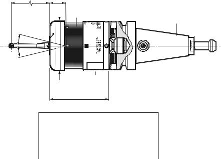
RMP60 features
RMP60 window
Battery cover
Ø63 (Ø2.48)
76 (2.99)
STYLUS OVERTRAVEL LIMITS
Dimensions mm (in)
A range of probe ready shanks is available from Renishaw upon request
|
Stylus length |
±X / ±Y |
Z |
|
|
50 (1.96) |
21 |
(0.82) |
11 (0.43) |
|
100 (3.93) |
37 |
(1.45) |
11 (0.43) |

RMP60 specification
Stylus trigger force
X/Y trigger forces vary, depending on trigger direction. There are 3 high force and 3 low force directions
|
X/Y direction |
Typical lowest force |
|
(50 mm stylus) |
0.75 N / 75 gf |
|
(2.64 ozf) |
|
|
Typical highest force |
|
|
1,4 N / 140 gf (4.92 ozf) |
|
|
Z direction |
4.90 N / 490 gf |
|
(17.28 ozf) |
|
|
RMP60 IP rating |
IPX8 |
|
RMP60 weight |
Without batteries |
|
(without shank) |
855 g (30.16 oz) |
|
With batteries |
|
|
901 g (31.79 oz) |
PROBE STATUS LED
|
LED |
Probe status |
Graphic hint |
|
|
colour |
|||
|
Unlit |
Stand-by mode |
||
|
Flashing |
Probe seated in |
||
|
green |
operating mode |
||
|
Flashing |
Probe triggered in |
||
|
red |
operating mode |
||
|
Flashing |
Probe seated in |
||
|
green |
operating mode |
||
|
and blue |
— low battery |
Flashing Probe triggered in red and operating mode blue — low battery
Constant
Battery dead
red
Max spin speed 1000 rev/min
![]()
Probe status LED
|
LEDs |
19 mm |
LEDs |
|
|
flashing |
flashing |
||
|
GREEN |
RED |
||
|
X / Y |
|||
|
Weak link (steel styli only) |
18° 18° |
||
|
Fitting stylus with weak |
|||
|
link onto RMP60 |
Fitting a weak link |
In the event of
2 Nm (1.7 lbf.ft)
excessive stylus
overtravel the weak link is designed
to break, thereby protecting the probe from damage.
Take care to avoid stressing the weak link during assembly.
5 mm AF
2 Nm (1.7 lbf.ft)
12 mm
(0.47 in)
Z
11 mm
Removing a broken weak link

10 Modes of operation
Modes of operation
The RMP60 probe can be in one of three modes:
1.Stand-by mode — The RMP60 is waiting for a switch-on signal .
2.Operating mode — Activated by one of the switch on methods described on this page. In this mode and the RMP60 is now ready for use.
3.Configuration mode — The trigger-logic configuration method allows a number of RMP60 set-up options to be configured by triggering the RMP60, including the switch-off options described on page 25.
RMP60 switch-on
RMP60 power on/off
Switch-on options are configurable
— see page 13.
Three switching methods can be used.
1.Radio start
Radio switch-on is commanded by
M code.
2.Spin start
Spin at 650 rev/min for 1 sec minimum (maximum 6 sec)
3.Shank switch
Note:
RMP60 will be turned on after 1 sec in all modes.
|
Modes of operation |
11 |
|||||
|
RMP60 switch-off |
||||||
|
Switch-off options are programmable |
3. |
Spin stop |
||||
|
Three switching methods can be used. |
(Only applies when spin on mode is |
|||||
|
1. Radio stop |
selected). |
|||||
|
Radio switch off is commanded by a |
A timer switch automatically swiches |
|||||
|
the probe off after 90 min from last |
||||||
|
M code. |
||||||
|
trigger off, if not spun off. |
||||||
|
(Only applies when radio turn on is |
||||||
|
selected). |
4. |
Shank switch |
||||
|
A timer automatically switches the probe off |
(Only applies when shank on mode is |
|||||
|
after 90 min from last trigger if not turned off |
selected). |
|||||
|
by M-code. |
||||||
|
2. Timer off (time out) |
||||||
|
Note: |
||||||
|
(Only applies when radio on/spin on |
||||||
|
After being turned on, the RMP60 must be |
||||||
|
mode is selected). |
||||||
|
on for a minimum of 1 sec (7 sec for spin |
||||||
|
The RMP60 will time out (12, 33 or |
||||||
|
off) before being turned off. |
||||||
|
134 sec) after the last probe trigger or |
||||||
|
reseat. |
||||||
© 2003 Renishaw. All rights reserved.
Renishaw® is a registered trademark
of Renishaw plc.
This document may not be copied
or reproduced in whole or in part,
or transferred to any other media or
language, by any means, without the
prior written permission of Renishaw.
The publication of material within this
document does not imply freedom
from the patent rights of Renishaw plc.
Renishaw Part no: H-2000-5219-01-A
Issued: 08.2003
Disclaimer
Considerable effort has been made to ensure
that the contents of this document are free from
inaccuracies and omissions. However, Renishaw
makes no warranties with respect to the
contents of this document and specifically
disclaims any implied warranties. Renishaw
reserves the right to make changes to this
document and to the product described herein
without obligation to notify any person of such
changes.
Trademarks
All brand names and product names used in this
document are trade names, service marks,
trademarks, or registered trademarks of their
respective owners.
- Home
- Brands
- Renishaw
- Kitchen Appliances
- RMP60
- Installation And User Manual
Manual for Renishaw RMP60 Kitchen Appliances (42 pages)
Specifications:
|
Renishaw RMP60: Read PDF Manual Online
Accompanying Data:
Renishaw RMP60 Kitchen Appliances, Measuring Instruments PDF Installation And User Manual (Updated: Saturday 4th of February 2023 10:08:12 PM)
Rating: 4.6 (rated by 62 users)
Compatible devices: OLP40, SP80, SCP600, REVO-2, RMP40, RP1, TRS1, APCA-45.
Recommended Documentation:
Renishaw RMP60: Text of Installation And User Manual
(Ocr-Read Version Summary of Contents, UPD: 04 February 2023)
-
25, 23 Stylus trigger force adjustment Stylus trigger force adjustment Spring force within the probe causes the stylus to sit in one unique position, and return to this position following each stylus deflection. Stylus trigger force is set by Renishaw. The user should only adjust trigger force in special circumstances e.g. excessive machine vibration or insufficient force to support the…
-
38, 36 Appendix 1 RMI (RADIO MACHINE INTERFACE) The RMI is fully described in User’s guide H-2000-5220 Appendix 1 A visual indication of system status is provided by light emitting diodes (LED’s). Status is continuously updated and indication is provided for START, LOW BATTERY, PROBE STATUS, ERROR, SIGNAL STRENGTH KEEP THE FRONT COVER CLEAN 3 1 4 LED LIGHT SIGNALS 1. Low…
-
18, 16 Note. When the RMP60 and RMI become partners the RMI records the RMP60 serial number. It is not possible for an RMI to be partners with more than one RMP60. It is possible for an RMP60 to be partners with more than one RMI, but the system will not work correctly if more than one partner RMI is powered on at any one time. RMP60-RMI partnership
… -
11, 9 Probe status LED Z X / Y 19 mm 11 mm 18° 18° LEDs flashing GREEN ➤ ➤ ➤ Probe status LED Weak link (steel styli only) Fitting stylus with weak link onto RMP60 Removing a broken weak link 5 mm AF 2 Nm (1.7 lbf.ft) 12 mm (0.47 in) 2 Nm (1.7 lbf.ft) In the event of excessive stylus overtravel the weak link is designed to break, thereby protecting the…
-
8, 6 Operating envelope Operating envelope RMP60 probe + RMI RMP60 and RMI must be within each others operating envelope shown. Range metres (feet) OPERATING AND SWITCH ON/OFF 90° 75° 60° 45° 30° 15° 0° 15° 30° 45° 60° 75° 90° 75° 60° 45° 30° 15° 0° 15° 45° 60° 75° 75° 60° 45° 30° 30° 45° 60° 75° 10 (33) 15 (49) 5 (16) 5 (16) 10 (3…
-
32, 30 M3 screw 2.5 mm AF 1 Nm (0.74 lbf.ft) Cover Outer diaphragm OUTER DIAPHRAGM REPLACEMENT 6. Fit new diaphragm over centre. 7. Locate outer edge of diaphragm to rest on outer edge of inner diaphragm. 8. Refit front cover and M3 screws. 9. Refit stylus and re-calibrate probe. Diaphragm replacement Inner diaphragm
… -
42, Renishaw plc New Mills, Wotton-under-Edge, Gloucestershire, GL12 8JR United Kingdom T +44 (0)1453 524524 F +44 (0)1453 524901 E [email protected] www.renishaw.com For worldwide contact details, please visit our main website at www.renishaw.com/contact *H-2000-5219-01-A*
… -
27, 25 Calibrating a system Calibration should be done in the following circumstances: 1. Before the system is used 2. When a new stylus is used. 3. To allow for machine thermal growth. 4. Poor relocation repeatability of the probe holder with machine spindle. It is important that calibration cycles are run at the measuring cycle feed rate to cancel out system errors. C…
-
17, 15 Setup is done by using the RMP60 trigger logic and powering on the RMI at a particular time during the process. Trigger logic is a method that allows user configuration of the options available in the RMP60. Trigger logic uses a sequence of RMP60 triggering and battery insertion followed by further RMP60 triggering. This leads the user through a series of choices allowing sele…
-
31, 29 Diaphragm replacement Diaphragm replacement RMP60 DIAPHRAGMS The probe mechanism is protected from coolant and debris by two diaphragms. These provide adequate protection under normal working conditions. The user should periodically check the outer diaphragm, for signs of damage. If this is evident replace the outer diaphragm. The user must not remove the inner diaphragm. If damaged, return…
-
21, 19 Battery life expectancy Alkaline — Two AA type (see page 20). Typical battery reserve life Using the standard alkaline battery at 5 % usage, typically the probe will continue to operate for approximately 2 weeks after a low battery warning is first indicated. Battery life expectancy Two AA type STAND-BY LIFE (days — max) STAND-BY LIFE (days — max) 5% USAGE 72 minutes/day (days — max) CONT…
-
39, 37 Appendix 1 3. Error Red Error, other outputs may be incorrect. Off: No Error. 4. Signal Green Full signal strength. Yellow Medium signal strength. Red: Low signal strength, radio link may fail. Off No signal detected. Green/off Flashing: RMI is acquisition mode, and can acquire a partner RMP. Red/yellow Flashing: RMI has (just) acquired a new partner RMP. Notes. 1. The pr…
-
5, 3 Contents Typical probe system with radio transmission ……………………………………………. 4 System performance ……………………………….. 5 Operating envelope ………………………………….. 6 RMP60 features ………………………………………. 7 RMP60 specification ………………………………… 8 Probe status LED ………..…
-
15, 13 Configuration using trigger logic START Remove batteries from probe. Hold stylus deflected and insert batteries. Release the stylus only after 15 seconds. The current probe settings review sequence, detailed on page 12 will always be displayed first. CONFIGURATION MODE after 15 seconds continued on next page Configuration using trigger logic SWITCH OFF MET…
DOC-2ef6643f:
Renishaw RMP60: Recommended Instructions
AC400A, WD1450, Lytecaster 1920LV, T7, EJCA01UP


-
INSTRUCTION BOOKLETRechargeable Salt & Pepper Mill SP-2For your safety and continued enjoyment of this product, always read the instruction book carefully before using.10ce113651_sp2_ib.indd 1 5/18/10 4:04:07 PM …
Rechargeable Salt & Pepper Mill SP-2 8
-
Electromagnetically Compatible Installation Guide Book Inverter Series WJ200 Hitachi Europe GmbH …
WJ200 Series Software 20
-
FINISH DETAILS FOR VCRB MODEL• Stainless Steel (SS), Black (BK), White(WH), Metallic Silver (MS), GraphiteGray (GG), Stone Gray (SG), Taupe(TP), Biscuit (BT), Cotton White (CW),Oyster Gray (OG), Golden Mist (GM),Lemonade (LE), Sage (SA), Mint Julep(MJ), Sea Glass (SE), Iridescent Blue(IB), Viking Blue (VB), Pumpkin (PM),Racing Red (RR), Apple Red (AR),Burgundy (BU), Plum (PL), C …
DDRB364 9
-
AwningOperating manual . . . . . . . . . . . . . . . 8MarkiseBedienungsanleitung. . . . . . . . . . . . 20Store extérieuruNotice d’utilisation . . . . . . . . . . . . . . 33ToldoInstrucciones de uso . . . . . . . . . . . . 46Tenda da soleIstruzioni per l’uso . . . . . . . . . . . . . . 58ZonneschermGebruiksaanwijzing . . . . . . . . . . . . . 70MarkiseBe …
PR2000 46
-
COCINA ELÉCTRICA PORTÁTIL MANUAL DE INSTRUCCIONES Atención. — Lea detenidamente este manual antes de utilizar el aparato por primera vez. — Guarde este manual para futuras consultas. — Si presta o vende el aparato a terceros, debe ir acompañado de su manual. — Incumplir las indicaciones de este manual será motivo de exención de garantía. …
TH-CE1000/1P 9
-
ENCordless Heated Jacket / Cordless Heated Vest INSTRUCTION MANUAL6FRMANUEL D’INSTRUCTIONS14DE � …
CJ105D 272
-
B-61ZX-E SeriesZX-E SeriesSmart Sensors (Inductive Displacement Type)ZX-E Series.FeaturesDesigned to meet your measurement needsWhat’s innovative about the ZX-E sensor is that the same ampli-fer unit can be attached to any one of five sensor headds; It’s sim-ply a matter of selecting the sensor head that best suits your measurement application. And there’s total compat …
ZX-E Series 16
-
SIWAREX JB stainless steel with ATEX certificate ________________________________________________________________________________________________________________________________________________________ Weighing systems SIWAREX JB stainless steel with ATEX certificate Compact Operating Instructions 06/2010 A5E01257284C-01 Introduction 1 Notes on handling the …
SIWAREX JB 24
-
cookmax ist eine Marke der PENTAGAST eG Philipp-Reis-Straße 9, D-36093 Künzell Tel: +49 (0) 66 1 / 93 48 3 – 0 / Fax: +49 (0) 66 1 / 93 48 3 — 25 [email protected] www.pentagast.de Vorbereitung Schrägschneider Artikel-Nr. 411033 (SG300T) Handbuch …
SG220 31
-
Solo DeluxeLadder TreestandPN 82068WARNING!You must fully read, understand and follow these warnings and instructions (written and video)! Failure to follow these instructions may cause serious injury or death!!You MUST also view the enclosed DVD BEFORE using your new treestand!!WEIGHT LIMITSINGLE USER300 LBS. X 1 TOTAL*DO NOT EXCEED THIS LIMIT!(* Includes al …
Solo Deluxe 12