
Ультразвуковой накладной расходометр
ER 3.4.0_
OPTISONIC 6300
Руководство по эксплуатации
© KROHNE 10/2011 — 4001688601 — MA OPTISONIC 6300 R01 ru
 11:47
11:47
OPTISWIRL 4200: монтаж, Пусконаладка и Проверка | KROHNE Tutorials
 06:06
06:06
OPTISONIC 3400 Ультразвуковые расходомеры
 06:37
06:37
OPTISONIC 6300 P: Portable ultrasonic clamp-on flowmeter | KROHNE
 07:03
07:03
Калибровочные установки КРОНЕ в России
 06:46
06:46
Монтаж портативного расходомера OPTISONIC 6300 P
 01:56
01:56
Stationary clamp-on flowmeter OPTISONIC 6300 | KROHNE
 01:52
01:52
OPTISONIC 6300 P starring in: «Come to grips.»
 06:06
06:06
KROHNE OPTISONIC 6300P Portable Ultrasonic Clamp-on Flowmeter | Instrumart
Ультразвуковой накладной расходометр ER…
Optisonic 6300, Ультразвуковой накладной расходометр
- Изображение
- Текст
Ультразвуковой накладной расходометр
ER 3.4.0_
OPTISONIC 6300
Руководство по эксплуатации
© KROHNE 10/2011 — 4001688601 — MA OPTISONIC 6300 R01 ru

Все права сохранены. Запрещается воспроизведение настоящего документа, или любой его части,
без предварительного письменного разрешения KROHNE Messtechnik GmbH.
Подлежит изменениям без предварительного уведомления.
2
www.krohne.com
10/2011 — 4001688601 — MA OPTISONIC 6300 R01 ru
Авторское право 2010 принадлежит
KROHNE Messtechnik GmbH — Ludwig-Krohne-Str. 5 — 47058
г. Дуйсбург (Германия)
:
Выходные данные издания
:::::::::::::::::::::::::::::::::

Содержание
3
www.krohne.com
10/2011 — 4001688601 — MA OPTISONIC 6300 R01 ru
OPTISONIC 6300
1
Правила техники безопасности
6
1.1
История версий программного обеспечения ……………………………………………………………….. 6
1.2
Назначение……………………………………………………………………………………………………………….. 7
1.3
Сертификаты…………………………………………………………………………………………………………….. 7
1.4
Правила техники безопасности изготовителя ……………………………………………………………… 8
1.4.1
Авторское право и защита информации ……………………………………………………………………………… 8
1.4.2
Заявление об ограничении ответственности……………………………………………………………………….. 8
1.4.3
Ответственность за качество изделия и гарантийные обязательства …………………………………… 9
1.4.4
Информация по документации …………………………………………………………………………………………… 9
1.4.5
Используемые предупреждающие знаки и графические обозначения ………………………………… 10
1.5
Инструкции по технике безопасности для пользователя ……………………………………………. 11
2
Описание прибора
12
2.1
Комплект поставки …………………………………………………………………………………………………… 12
2.2
Описание прибора …………………………………………………………………………………………………… 13
2.3
Шильды…………………………………………………………………………………………………………………… 14
2.3.1
Обзор………………………………………………………………………………………………………………………………. 14
2.3.2
Измерительный датчик …………………………………………………………………………………………………….. 14
2.3.3
Электронный конвертор……………………………………………………………………………………………………. 15
2.3.4
Электрическое подключение входных и выходных сигналов (на примере базовой версии) …. 16
3
Монтаж
17
3.1
Указания по монтажу ……………………………………………………………………………………………….. 17
3.2
Хранение ………………………………………………………………………………………………………………… 17
3.3
Транспортировка и перемещение …………………………………………………………………………….. 17
3.4
Требования к подготовке к монтажу………………………………………………………………………….. 17
3.4.1
Требования к окружающей среде ……………………………………………………………………………………… 17
3.4.2
Требования к монтажу электронного конвертора……………………………………………………………….. 18
3.5
Требования к монтажу……………………………………………………………………………………………… 18
3.5.1
Вход, выход и рекомендуемая площадка для установки…………………………………………………….. 19
3.5.2
Горизонтальные участки трубопровода большой длины ……………………………………………………. 19
3.5.3
Свободная подача или слив продукта……………………………………………………………………………….. 20
3.5.4
Нисходящий участок трубопровода длиной 5 м / 16 футов…………………………………………………. 20
3.5.5
Положение регулирующего клапана …………………………………………………………………………………. 21
3.5.6
Расположение насоса………………………………………………………………………………………………………. 21
3.5.7
Диаметры трубы и конструкция датчика ……………………………………………………………………………. 22
3.5.8
Параметры трубы и рабочего продукта …………………………………………………………………………….. 22
3.6
Монтаж расходомера……………………………………………………………………………………………….. 23
3.6.1
Основные моменты монтажа механической части……………………………………………………………… 23
3.6.2
Инструкции по монтажу для версий малого и среднего размера ………………………………………… 25
3.6.3
Инструкции по монтажу для версии большого размера ……………………………………………………… 27
3.7
Монтаж конвертора………………………………………………………………………………………………….. 29
3.7.1
Монтаж UFC 300 F …………………………………………………………………………………………………………… 29
3.7.2
Поворот дисплея в конверторе полевой версии ………………………………………………………………… 29
3.7.3
Монтаж UFC 300 W ………………………………………………………………………………………………………….. 30
4
Электрический монтаж
31
4.1
Правила техники безопасности ………………………………………………………………………………… 31
4.2
Конструкция различных версий исполнения корпусов ……………………………………………….. 31
4.2.1 UFC 300 F………………………………………………………………………………………………………………………… 31

Содержание
4
www.krohne.com
10/2011 — 4001688601 — MA OPTISONIC 6300 R01 ru
OPTISONIC 6300
4.2.2 UFC 300 W ………………………………………………………………………………………………………………………. 32
4.3
Электрические присоединения…………………………………………………………………………………. 33
4.3.1
Сигнальный кабель к измерительному датчику …………………………………………………………………. 33
4.3.2
Сигнальный кабель и источник питания электронного конвертора ……………………………………… 35
4.3.3
Правильная укладка электрических кабелей……………………………………………………………………… 36
4.4
Условные обозначения на электрических схемах………………………………………………………. 37
4.5
Базовая версия входов и выходов ……………………………………………………………………………. 38
4.5.1
Фиксированные неизменяемые комбинации входных/выходных сигналов ………………………….. 39
4.5.2
Базовая версия входных и выходных сигналов………………………………………………………………….. 41
4.5.3
Подключение по протоколу HART
®………………………………………………………………………………………………………….. 44
4.6
Модульные входные и выходные сигналы ………………………………………………………………… 45
4.6.1
Изменяемые комбинации входных и выходных сигналов …………………………………………………… 45
4.6.2
Модульные входные / выходные сигналы и сетевые технологии………………………………………… 47
4.6.3
Подключение по протоколу HART
®………………………………………………………………………………………………………….. 55
5
Пуско-наладочные работы
57
5.1
Общие указания по программированию параметров …………………………………………………. 57
5.2
Начало измерения для версии малого / среднего размера ………………………………………… 61
5.3
Начало измерения для версии большого размера …………………………………………………….. 62
5.4
Монтаж механической части версии большого размера…………………………………………….. 64
6
Эксплуатация
73
6.1
Обзор меню …………………………………………………………………………………………………………….. 73
6.2
Структура меню……………………………………………………………………………………………………….. 74
6.2.1
Быстрая настройка…………………………………………………………………………………………………………… 74
6.2.2
Тест ………………………………………………………………………………………………………………………………… 77
6.2.3
Настройка ……………………………………………………………………………………………………………………….. 79
6.2.4
Изменить настройки…………………………………………………………………………………………………………. 90
6.3
Описание функции…………………………………………………………………………………………………… 91
6.4
Сообщений об ошибке……………………………………………………………………………………………. 100
7
Техническое обслуживание
103
7.1
Периодическое техническое обслуживание …………………………………………………………….. 103
7.1.1
Повторное нанесение консистентной смазки на сенсоры …………………………………………………. 103
7.2
Очистка …………………………………………………………………………………………………………………. 104
7.3
Замена электронного блока ……………………………………………………………………………………. 104
7.3.1
Полевая версия……………………………………………………………………………………………………………… 105
7.3.2
Версия для настенного монтажа……………………………………………………………………………………… 107
7.4
Замена главного предохранителя …………………………………………………………………………… 109
7.4.1
Полевая версия……………………………………………………………………………………………………………… 110
7.4.2
Версия для настенного монтажа……………………………………………………………………………………… 110
7.5
Доступность запасных частей…………………………………………………………………………………. 111
7.6
Доступность сервисного обслуживания …………………………………………………………………… 111
7.7
Возврат прибора изготовителю ………………………………………………………………………………. 111
7.7.1
Информация общего характера………………………………………………………………………………………. 111
7.7.2
Образец бланка, прилагаемого к прибору в случае возврата (для снятия копии) ………………. 112
7.8
Утилизация ……………………………………………………………………………………………………………. 112

Содержание
5
www.krohne.com
10/2011 — 4001688601 — MA OPTISONIC 6300 R01 ru
OPTISONIC 6300
8
Технические характеристики
113
8.1
Принцип измереня …………………………………………………………………………………………………. 113
8.2
Технические характеристики ………………………………………………………………………………….. 114
8.3
Габаритные размеры и вес …………………………………………………………………………………….. 123
8.3.1
Корпус …………………………………………………………………………………………………………………………… 123
8.3.2
Накладной датчик и кабельная коробка…………………………………………………………………………… 124
8.3.3
Монтажная пластина, полевое исполнение……………………………………………………………………… 126
8.3.4
Монтажная пластина, исполнение для настенного монтажа …………………………………………….. 126
9
Примечания
127

Правила техники безопасности, 1 история версий программного обеспечения
Страница 6
- Изображение
- Текст
1
Правила техники безопасности
6
OPTISONIC 6300
www.krohne.com
10/2011 — 4001688601 — MA OPTISONIC 6300 R01 ru
1.1
История версий программного обеспечения
При работе со всеми приборами GDC необходимо учитывать номер «Electronic Revision» (ER), что
означает «Изменения в электронике». ER указывает номер текущей версии электронного
оборудования, в соответствии с требованиями NE 53. С помощью номера ER легко определить,
устранялись ли какие-либо неисправности, вносились ли значительные изменения в электронное
оборудование, а также установить, как данные работы повлияли на совместимость.
Изменения и их влияние на совместимость
1
Изменения с обратной совместимостью и устранение ошибок без изменения
работоспособности (например, орфографические ошибки на дисплее)
2-_
Изменения интерфейсов с обратной совместимостью оборудования и/или программного
обеспечения:
H
HART
®
P
PROFIBUS
F
Foundation Fieldbus
M
Modbus
X
все интерфейсы
3-_
Изменения входов и выходов с обратной совместимостью оборудования и/или
программного обеспечения:
I
Токовый выход
F, P
Импульсный или частотный выход
S
Выход состояния
C
Вход управления
CI
Токовый вход
X
Все входы и выходы
4
Изменения с обратной совместимостью с добавлением функций
5
Несовместимые изменения, т.е. электронное оборудование должно быть заменено.
Информация!
В таблице ниже символ «x» используется вместо возможных многозначных буквенно-цифровых
комбинаций в зависимости от доступной версии.

Правила техники безопасности, 2 назначение, 3 сертификаты
Страница 7
- Изображение
- Текст
Правила техники безопасности
1
7
OPTISONIC 6300
www.krohne.com
10/2011 — 4001688601 — MA OPTISONIC 6300 R01 ru
1.2
Назначение
Полный список функций накладного расходомера включает в себя непрерывное измерение
фактического объемного расхода, массового расхода, скорости расхода, скорости звука,
коэффициента усиления, отношения сигнал-шум и результата диагностики.
1.3
Сертификаты
В соответствии с обязательством по осуществлению послепродажного обслуживания и
обеспечению безопасного использования описанное в настоящем документе устройство
отвечает следующим требованиям техники безопасности:
• Директива по электромагнитной совместимости 89 / 336 / ЕЭС и 93 / 68 / ЕЭС в соответствии с
EN 61326-1 (1997)
и A1 (1998), A2 (2001)
• Директивы по низковольтным устройствам 73 / 23 / ЕЭС и 93 / 68 / ЕЭС в соответствии с
EN 61010-1 (2001)
Все приборы имеют маркировку CE и соответствуют требованиям стандарта NAMUR NE 21 / 04.
Опасность!
На приборы, которые эксплуатируются во взрывоопасных зонах, распространяются
дополнительные нормы безопасности. Обратитесь к документации на изделия
взрывозащищенного исполнения.

Правила техники безопасности, 4 правила техники безопасности изготовителя
Страница 8
- Изображение
- Текст
1
Правила техники безопасности
8
OPTISONIC 6300
www.krohne.com
10/2011 — 4001688601 — MA OPTISONIC 6300 R01 ru
1.4
Правила техники безопасности изготовителя
1.4.1
Авторское право и защита информации
Данные, представленные в настоящем документе, подбирались с большой тщательностью. Тем не
менее, мы не гарантируем, что его информационное наполнение не содержит ошибок, является
полным или актуальным.
Информационное наполнение и иные материалы в составе настоящего документа являются
объектами авторского права. Участие третьих лиц также признается таковым. Воспроизведение,
переработка, распространение и иное использование в любых целях сверх того, что разрешено
авторским правом, требует письменного разрешения соответствующего автора и/или
производителя.
Изготовитель во всех случаях старается соблюсти авторское право других лиц и опираться на
работы, созданные внутри компании, либо на доступные для общего пользования труды, не
охраняемые авторским правом.
Подборка персональных данных (таких как названия, фактические адреса, либо адреса электронной
почты) в документации производителя по возможности всегда осуществляется на добровольной
основе. Исходя из соображений целесообразности, мы при любых обстоятельствах стараемся
использовать продукты и услуги без предоставления каких-либо персональных данных.
Подчеркиваем, что передача данных по сети Интернет (например, при взаимодействии посредством
электронной почты), может подразумевать бреши в системе безопасности. Обеспечение
полноценной защиты таких данных от несанкционированного доступа третьих лиц не всегда
представляется возможным.
Настоящим строго воспрещается использование контактных данных, публикуемых в рамках наших
обязательств печатать выходные данные, в целях отправки нам любой информации рекламного или
информационного характера, если таковая не была запрошена нами напрямую.
1.4.2
Заявление об ограничении ответственности
Изготовитель не несет ответственность за всякий ущерб любого рода, возникший в результате
использования его изделия, включая прямые, косвенные, случайные, присуждаемые в порядке
наказания и последующие убытки, но не ограничиваясь ими.
Настоящее заявление об ограничении ответственности не применяется в случае, если
производитель действовал намеренно, либо проявил грубую небрежность. В случае если любая
применяемая правовая норма не допускает таких ограничений по подразумеваемым гарантиям,
либо не предусматривает исключения ограничения определенного ущерба, Вы можете, если данная
правовая норма распространяется на Вас, не подпадать под действие некоторых или всех
перечисленных выше заявлений об ограничении ответственности, исключений или ограничений.
На любой приобретенный у изготовителя продукт распространяются гарантийные обязательства
согласно соответствующей документации на изделие и положениям и условиям нашего договора о
купле-продаже.
Производитель оставляет за собой право вносить в содержание своих документов, в том числе и в
настоящее заявление об ограничении ответственности, изменения любого рода, в любой момент
времени, на любых основаниях, без предварительного уведомления и в любом случае не несет
никакой ответственности за возможные последствия таких изменений.

Правила техники безопасности
1
9
OPTISONIC 6300
www.krohne.com
10/2011 — 4001688601 — MA OPTISONIC 6300 R01 ru
1.4.3
Ответственность за качество изделия и гарантийные обязательства
Ответственность за надлежащее использование устройства в соответствии с его функциональным
назначением возлагается на пользователя. Изготовитель не признает никакой ответственности за
последствия ненадлежащего применения со стороны пользователя. Некорректный монтаж и
эксплуатация устройств (систем) с нарушением установленных режимов влечет за собой утрату
гарантии. При этом действуют соответствующие «Типовые положения и условия», которые
формируют основу договора купли-продажи.
1.4.4
Информация по документации
Во избежание травмирования пользователя или вывода прибора из строя следует в обязательном
порядке прочесть содержащиеся в настоящем документе материалы и соблюдать действующие
государственные стандарты, требования, нормы и правила техники безопасности, в том числе и по
предупреждению несчастных случаев.
Если настоящий документ составлен на иностранном языке, при возникновении сложностей с
пониманием данного текста, мы рекомендуем обратиться за содействием в ближайшее
региональное представительство. Производитель не несет ответственности за любой ущерб или
вред, вызванный некорректной интерпретацией положений настоящего документа.
Настоящий документ предоставляется с целью оказания содействия в организации такого
эксплуатационного режима, который позволит безопасно и эффективно применять данный прибор.
Кроме того, в документе приводятся требующие особого внимания аспекты и предупредительные
меры по обеспечению безопасности, которые представлены ниже в виде графических символов-
пиктограмм.

1
Правила техники безопасности
10
OPTISONIC 6300
www.krohne.com
10/2011 — 4001688601 — MA OPTISONIC 6300 R01 ru
1.4.5
Используемые предупреждающие знаки и графические обозначения
Предупреждения относительно безопасного пользования обозначаются следующими символами.
• ПОГРУЗОЧНО-РАЗГРУЗОЧНЫЕ ОПЕРАЦИИ
Данный символ обозначает все указания к действиям и операциям, которые пользователю
надлежит выполнять в определенной предписанной последовательности.
i
РЕЗУЛЬТАТ
Настоящий символ относится ко всем важным последствиям совершенных ранее действий и
операций.
Опасность!
Настоящая информация относится к непосредственным рискам при работе с электричеством.
Опасность!
Данный предупреждающий знак относится к непосредственной опасности получения ожогов в
результате контакта с источником тепла или с горячими поверхностями.
Опасность!
Данный предупреждающий знак относится к непосредственным рискам, возникающим при
эксплуатации этого измерительного прибора во взрывоопасных зонах.
Опасность!
В обязательном порядке соблюдайте данные предупреждения. Даже частичное несоблюдение
этого предупреждающего знака может повлечь за собой серьезный ущерб здоровью вплоть до
летального исхода. Кроме того, имеет место риск возникновения серьезных неисправностей
самого измерительного прибора либо элементов технических сооружений и технологического
оборудования пользователя.
Внимание!
Пренебрежение данным предостережением относительно безопасного пользования и даже
частичное его несоблюдение представляют серьезную опасность для здоровья. Кроме того,
имеет место риск возникновения серьезных неисправностей самого измерительного прибора
либо элементов технических сооружений и технологического оборудования пользователя.
Осторожно!
Несоблюдение настоящих указаний может повлечь за собой серьезные неисправности самого
измерительного прибора либо элементов технических сооружений и технологического
оборудования пользователя.
Информация!
Данные указания содержат важную информацию по погрузочно-разгрузочным работам, переноске
и обращению с прибором.
Официальное уведомление!
Настоящее примечание содержит информацию по законодательно установленным предписаниям
и стандартам.

Комментарии
-
Contents
-
Table of Contents
-
Bookmarks
Quick Links
OPTISONIC 6300
OPTISONIC 6300
OPTISONIC 6300
OPTISONIC 6300
Ultrasonic clamp-on flowmeter
ER 3.4.0_
© KROHNE 07/2009 — 4000263902 — HB OPTISONIC 6300 R03 en
Handbook
Handbook
Handbook
Handbook
Related Manuals for KROHNE OPTISONIC 6300
Summary of Contents for KROHNE OPTISONIC 6300
-
Page 1
OPTISONIC 6300 OPTISONIC 6300 OPTISONIC 6300 OPTISONIC 6300 Handbook Handbook Handbook Handbook Ultrasonic clamp-on flowmeter ER 3.4.0_ © KROHNE 07/2009 — 4000263902 — HB OPTISONIC 6300 R03 en… -
Page 2
KROHNE Messtechnik GmbH & Co. KG. Subject to change without notice. Copyright 2009 by KROHNE Messtechnik GmbH & Co. KG — Ludwig-Krohne-Straße 5 — 47058 Duisburg www.krohne.com 07/2009 — 4000263902 — HB OPTISONIC 6300 R03 en… -
Page 3: Table Of Contents
3.7 Mounting of converter ………………..27 3.7.1 Mounting of UFC 300 F………………….27 3.7.2 Turning the display of the field housing version …………..27 3.7.3 Mounting of UFC 300 W………………….28 4 Electrical connections 07/2009 — 4000263902 — HB OPTISONIC 6300 R03 en www.krohne.com…
-
Page 4
7.4.1 Field version……………………103 7.4.2 Wall version……………………. 103 7.5 Spare parts availability………………..104 7.6 Availability of services ………………..104 7.7 Returning the device to the manufacturer…………..104 7.7.1 General information………………….104 www.krohne.com 07/2009 — 4000263902 — HB OPTISONIC 6300 R03 en… -
Page 5
8.3 Dimensions and weights ………………..115 8.3.1 Housing ……………………..115 8.3.2 Clamp-on sensor and cable box ………………116 8.3.3 Mounting plate, field housing ………………… 118 8.3.4 Mounting plate, wall-mounted housing …………….118 9 Notes 07/2009 — 4000263902 — HB OPTISONIC 6300 R03 en www.krohne.com… -
Page 6: Safety Instructions
• EMC Directive 89 / 336 / EEC and 93 / 68 / EEC in conjunction with EN 61326-1 (1997) and A1 (1998), A2 (2001) • Low-Voltage Directives 73 / 23 / EEC and 93 / 68 / EEC in conjunction with EN 61010-1 (2001) www.krohne.com 07/2009 — 4000263902 — HB OPTISONIC 6300 R03 en…
-
Page 7
All devices are based on the CE marking and meet the requirements of NAMUR Guideline NE 21 / 04. DANGER! For devices used in hazardous areas, additional safety notes apply; please refer to the Ex documentation. 07/2009 — 4000263902 — HB OPTISONIC 6300 R03 en www.krohne.com… -
Page 8: Safety Instructions From The Manufacturer
The manufacturer reserves the right to alter the content of its documents, including this disclaimer in any way, at any time, for any reason, without prior notification, and will not be liable in any way for possible consequences of such changes. www.krohne.com 07/2009 — 4000263902 — HB OPTISONIC 6300 R03 en…
-
Page 9: Product Liability And Warranty
This document is provided to help you establish operating conditions, which will permit safe and efficient use of this device. Special considerations and precautions are also described in the document, which appear in the form of underneath icons. 07/2009 — 4000263902 — HB OPTISONIC 6300 R03 en www.krohne.com…
-
Page 10: Warnings And Symbols Used
In general, devices from the manufacturer may only be installed, commissioned, operated and maintained by properly trained and authorized personnel. This document is provided to help you establish operating conditions, which will permit safe and efficient use of this device. www.krohne.com 07/2009 — 4000263902 — HB OPTISONIC 6300 R03 en…
-
Page 11: Device Description
® 7 Mineral coupling grease (standard versions) or high temperature contactgel Pyrogel (XT versions) 8 Signal cable plus connector cap (XT versions have a protection sleeve around the signal cable). 07/2009 — 4000263902 — HB OPTISONIC 6300 R03 en www.krohne.com…
-
Page 12: Device Description
The ultrasonic clamp-on flowmeter can be fitted on the outside of piping to measure the flow rate of liquids. The device is a combination of one up to two clamp-on sensor(s) and one ultrasonic flow converter. Figure 2-2: System configuration possibilities www.krohne.com 07/2009 — 4000263902 — HB OPTISONIC 6300 R03 en…
-
Page 13: Nameplates
2 Protection category 3 Calibration number 4 Process temperature (-40…+200°C for XT version) 5 Manufacturing year 6 Serial number 7 Device type (yyy = small, medium or large) 8 Manufacturer 07/2009 — 4000263902 — HB OPTISONIC 6300 R03 en www.krohne.com…
-
Page 14: Signal Converter
1 Manufacturer 2 Device type 3 Manufacturing year 4 Serial number sensor 1 + short code flow sensor 5 Serial number sensor 2 + short code flow sensor 6 Empty www.krohne.com 07/2009 — 4000263902 — HB OPTISONIC 6300 R03 en…
-
Page 15: Electrical Connection Data Of Inputs/Outputs (Example Of Basic Version)
• A = active mode; the signal converter supplies the power for connection of the subsequent devices • P = passive mode; external power supply required for operation of the subsequent devices • N/C = connection terminals not connected 07/2009 — 4000263902 — HB OPTISONIC 6300 R03 en www.krohne.com…
-
Page 16: Installation
• Suitable for indoor and outdoor use and certified for operating up to an altitude of 2000 m / 6562 ft • IP class 66/67 CAUTION! The device should be protected from corrosive chemicals or gases and dust / particles accumulation. www.krohne.com 07/2009 — 4000263902 — HB OPTISONIC 6300 R03 en…
-
Page 17: Installation Requirements Signal Converter
Additionally flow profile distortion is possible. CAUTION! If you program the diameter, please note that you use the outer diameter of the pipe. 07/2009 — 4000263902 — HB OPTISONIC 6300 R03 en www.krohne.com…
-
Page 18: Inlet, Outlet And Recommended Mounting Area
• If not possible, ensure adequate velocity to prevent air, gas or vapor from collecting in upper part. • In partially filled pipes, the clamp-on flowmeter will report incorrect flow rates, or not measure. Figure 3-2: Long horizontal pipes www.krohne.com 07/2009 — 4000263902 — HB OPTISONIC 6300 R03 en…
-
Page 19: Open Feed Or Discharge
Figure 3-4: Down going pipeline over 5 m /16 ft length 3.5.5 Position of control valve Always install control valves downstream of flowmeter in order to avoid cavitation or distortion of flow profile. Figure 3-5: Position of control valve 07/2009 — 4000263902 — HB OPTISONIC 6300 R03 en www.krohne.com…
-
Page 20: Position Of Pump
3.5.7 Pipe diameters and sensor construction Figure 3-7: Measuring modes 1 Z-mode 2 V-mode 3 W-mode 3.5.8 Pipe and media parameters INFORMATION! Detailed databases of most pipe and media parameters are on the supplied CD. www.krohne.com 07/2009 — 4000263902 — HB OPTISONIC 6300 R03 en…
-
Page 21: Installation Of The Flowmeter
Installation of the rails with the metal straps Installation of the rails with the metal straps Installation of the rails with the metal straps • 8: Repeat steps 1…7 at the other side of the rail. 07/2009 — 4000263902 — HB OPTISONIC 6300 R03 en www.krohne.com…
-
Page 22
• Slide the transducer 2 to the advised mounting distance 3 (menu X9.4). • Lock the transducer by turning the locking knob 1 clockwise. Greasing the transducer surfaces Greasing the transducer surfaces Greasing the transducer surfaces Greasing the transducer surfaces www.krohne.com 07/2009 — 4000263902 — HB OPTISONIC 6300 R03 en… -
Page 23: Installation Instructions For Small And Medium Version
Figure 3-8: Procedure for installation of small or medium version 1 Rail, small version 2 Rail, medium version 3 Choose for V-mode or … 4 Choose for W-mode 5 Make settings in converter 07/2009 — 4000263902 — HB OPTISONIC 6300 R03 en www.krohne.com…
-
Page 24
3 Small version: single pipe / dual path 4 Medium version: single pipe / dual path 5 Small version: dual pipe / single path 6 Medium version: dual pipe / single path www.krohne.com 07/2009 — 4000263902 — HB OPTISONIC 6300 R03 en… -
Page 25: Installation Instructions For Large Version
1 Enter the values for the installation menu, X1…X9.8.4 2 Read the advised mounting distance in menu X9.8.5 3 Choose for Z-mode (default) or … 4 Choose for V-mode 5 Finish the installation menu 07/2009 — 4000263902 — HB OPTISONIC 6300 R03 en www.krohne.com…
-
Page 26
INSTALLATION OPTISONIC 6300 Figure 3-11: Device versions 1 Single pipe, single path 2 Single pipe, dual path 3 Dual pipe www.krohne.com 07/2009 — 4000263902 — HB OPTISONIC 6300 R03 en… -
Page 27: Mounting Of Converter
Each time a housing cover is opened, the thread should be cleaned and greased. Use only resin- free and acid-free grease. Ensure that the housing gasket is properly fitted, clean and undamaged. 07/2009 — 4000263902 — HB OPTISONIC 6300 R03 en www.krohne.com…
-
Page 28: Mounting Of Ufc 300 W
• Position lock washers and nuts on the housing bolts, tighten nuts slightly. • Align housing, tighten nuts firmly. • Observe max. allowed length of 30 m / 98.4 ft for the signal cable. www.krohne.com 07/2009 — 4000263902 — HB OPTISONIC 6300 R03 en…
-
Page 29: Electrical Connections
2 Cover, terminal compartment for power supply and inputs/outputs 3 Cable entry for power 4 Cable entry for inputs/outputs 5 Cable entry for sensor cable 6 Cover, sensor terminal compartment 07/2009 — 4000263902 — HB OPTISONIC 6300 R03 en www.krohne.com…
-
Page 30: Ufc 300 W
2 Cover for the three separate terminal compartments for power, sensor connection and inputs/outputs 3 Locking screw, 1/2 turn left/right to open/close cover 2 4 Sensor terminal compartment 5 Terminal compartment for inputs/outputs 6 Power terminal compartment, open separate shock-hazard protection cover www.krohne.com 07/2009 — 4000263902 — HB OPTISONIC 6300 R03 en…
-
Page 31: Electrical Connection
1 Put in the connector. 2 Turn knob to secure the connector. CAUTION! For XT versions: check if the signal cable is heat protected with the protection sleeve of 1 meter / 40″. 07/2009 — 4000263902 — HB OPTISONIC 6300 R03 en www.krohne.com…
-
Page 32
1 Connect the blue cable to the UP rail. 2 Connect the green cable to the DOWN rail. 3 Make connections in cable box. 4 Cable to converter 5 Turn the screws clockwise to secure the caps. www.krohne.com 07/2009 — 4000263902 — HB OPTISONIC 6300 R03 en… -
Page 33: Signal Cable And Power Supply Signal Converter
1 Connect blue cable to 1U (to 2U for 2 sensor) and the green cable to 1D (2D for 2 sensor) 2 Communication I/O 3 Power supply: 24 VAC/DC or 100…240 VAC 07/2009 — 4000263902 — HB OPTISONIC 6300 R03 en www.krohne.com…
-
Page 34
U-clamp terminal in the terminal compartment of the signal converter. • When connecting to functional extra-low voltages, provide a facility for protective separation (PELV) (VDE 0100 / VDE 0106 and/or IEC 364 / IEC 536 or relevant national regulations). www.krohne.com 07/2009 — 4000263902 — HB OPTISONIC 6300 R03 en… -
Page 35: Laying Electrical Cables Correctly
2 Tighten the screw connection of the cable entry securely. 3 Never mount the housing with the cable entries facing upwards. 4 Seal cable entries that are not needed with a plug. 07/2009 — 4000263902 — HB OPTISONIC 6300 R03 en www.krohne.com…
-
Page 36: Description Of The Electrical Symbols
Electronic or electromagnetic counter At frequencies above 100 Hz, shielded cables must be used to connect the counters. Internal resistance of the counter Button, NO contact or similar Table 4-1: Description of symbols www.krohne.com 07/2009 — 4000263902 — HB OPTISONIC 6300 R03 en…
-
Page 37: Basic Inputs And Outputs
• 1 status output, • 1 control input. The pulse output can also be set as a status output. One of the status outputs can be set as a control input. 07/2009 — 4000263902 — HB OPTISONIC 6300 R03 en www.krohne.com…
-
Page 38: Fixed, Non-Alterable Input/Output Versions
1 function changed by reconnection 2 changeable • The grey boxes in the tables denote unassigned or unused connection terminals. • Connection terminal A+ is only operable in the basic input/output version. www.krohne.com 07/2009 — 4000263902 — HB OPTISONIC 6300 R03 en…
-
Page 39
Signal converter monitors cable breaks and short circuits as per EN 60947-5-6. Errors indicated on LCD display. Error messages possible via status output. Active current input Passive current input No additional module installed No further module possible 07/2009 — 4000263902 — HB OPTISONIC 6300 R03 en www.krohne.com… -
Page 40: Basic Inputs/Outputs
= 24 VDC nominal int,nom ≤ 32 VDC • U • I ≤ 22 mA ≥ 1.8 • U ≤ (U • R ) / I Figure 4-12: Current output passive I www.krohne.com 07/2009 — 4000263902 — HB OPTISONIC 6300 R03 en…
-
Page 41
) / I L, min • Can also be set as a status output; for the electrical connection, see status output connection diagram. Figure 4-13: Pulse frequency output passive P 07/2009 — 4000263902 — HB OPTISONIC 6300 R03 en www.krohne.com… -
Page 42
Contact closed (on): U = 2.8 mA • Can also be set as a status output; for the electrical connection, see status output connection diagram. Figure 4-15: Control input passive C 1 Signal www.krohne.com 07/2009 — 4000263902 — HB OPTISONIC 6300 R03 en… -
Page 43: Hart ® Connection
1 Basic I/O: terminals A and A+ 2 Modular I/O: terminals C- and C ® 3 HART communicator communicator must be R ≥ 230 Ω. ® The parallel resistance to the HART 07/2009 — 4000263902 — HB OPTISONIC 6300 R03 en www.krohne.com…
-
Page 44: Modular Inputs And Outputs
2 option modules for term. A + B passive ® + HART passive 7 _ _ max. 2 option modules for term. A + B NAMUR ® + HART active www.krohne.com 07/2009 — 4000263902 — HB OPTISONIC 6300 R03 en…
-
Page 45
Signal converter monitors cable breaks and short circuits as per EN 60947-5-6. Errors indicated on LCD display. Error messages possible via status output. Active current input Passive current input No additional module installed No further module possible 07/2009 — 4000263902 — HB OPTISONIC 6300 R03 en www.krohne.com… -
Page 46: Modular Inputs/Outputs And Bus Systems
≤ (U • R ) / I • X designates the connection terminals A, B or C, depending on the version of the signal converter. Figure 4-19: Current output passive I www.krohne.com 07/2009 — 4000263902 — HB OPTISONIC 6300 R03 en…
-
Page 47
) / I L, min • X designates the connection terminals A, B or D, depending on the version of the signal converter. Figure 4-20: Pulse / frequency output active P 07/2009 — 4000263902 — HB OPTISONIC 6300 R03 en www.krohne.com… -
Page 48
• Can also be set as a status output; see status output connection diagram. • X designates the connection terminals A, B or D, depending on the version of the signal converter. Figure 4-21: Pulse frequency output passive P www.krohne.com 07/2009 — 4000263902 — HB OPTISONIC 6300 R03 en… -
Page 49
• X designates the connection terminals A, B or D, depending on the version of the signal converter. Figure 4-22: Pulse and frequency output passive P to NAMUR EN 60947-5-6 07/2009 — 4000263902 — HB OPTISONIC 6300 R03 en www.krohne.com… -
Page 50
• The output is open when the device is de-energized. • X designates the connection terminals A, B or D, depending on the version of the signal converter. Figure 4-24: Status output / limit switch passive S www.krohne.com 07/2009 — 4000263902 — HB OPTISONIC 6300 R03 en… -
Page 51
• X designates the connection terminals A, B or D, depending on the version of the signal converter. Figure 4-25: Status output / limit switch S to NAMUR EN 60947-5-6 07/2009 — 4000263902 — HB OPTISONIC 6300 R03 en www.krohne.com… -
Page 52
Contact closed (on): U = 1.9 mA • X designates the connection terminals A or B, depending on the version of the signal converter. Figure 4-27: Control input passive C 1 Signal www.krohne.com 07/2009 — 4000263902 — HB OPTISONIC 6300 R03 en… -
Page 53
≤ 1.2 V with I ≥ 6.7 mA • X designates the connection terminals A or B, depending on the version of the signal converter. Figure 4-28: Control input active C to NAMUR EN 60947-5-6 07/2009 — 4000263902 — HB OPTISONIC 6300 R03 en www.krohne.com… -
Page 54: Hart ® Connection
1 Basic I/O: terminals A and A+ 2 Modular I/O: terminals C- and C ® 3 HART communicator communicator must be R ≥ 230 Ω. ® The parallel resistance to the HART www.krohne.com 07/2009 — 4000263902 — HB OPTISONIC 6300 R03 en…
-
Page 55
Figure 4-30: HART connection passive (I 1 Basic I/O: terminals A- and A 2 Modular I/O: terminals C- and C ® 3 HART communicator ® 4 Other HART — capable devices 07/2009 — 4000263902 — HB OPTISONIC 6300 R03 en www.krohne.com… -
Page 56: Start-Up
Esc (> + ↑) Return to menu mode Return to sub-menu or without acceptance of function without data acceptance of data Table 5-1: Description of key functionality www.krohne.com 07/2009 — 4000263902 — HB OPTISONIC 6300 R03 en…
-
Page 57
Start installation menu • Connect converter to power supply and power up converter. First and second page appear intermittently • Keep left button «>» pressed, until in display appears «release key now». 07/2009 — 4000263902 — HB OPTISONIC 6300 R03 en www.krohne.com… -
Page 58
> ↓ > fill in using ↑ ↓ > X6.13 viscosity > ↑ ↓ pipe data 2 > ↑ ↓ X7.1 copy pipe 1 data > start to copy ? www.krohne.com 07/2009 — 4000263902 — HB OPTISONIC 6300 R03 en… -
Page 59
(underneath X10 becomes active if two pipes or two paths (underneath X10 becomes active if two pipes or two paths are selected in X4 or X5) ↑ ↓ install transd. 2 > submenus identical to X9.1 up to X9.12 07/2009 — 4000263902 — HB OPTISONIC 6300 R03 en www.krohne.com… -
Page 60: Start Measurement Of Small / Medium Version
• X9.12: End Installation? Enter «Yes» to save the installation. The measurement screen will appear. • Mount the cover (see the section «mounting the cover» in chapter «General mechanical installation») www.krohne.com 07/2009 — 4000263902 — HB OPTISONIC 6300 R03 en…
-
Page 61: Start Measurement Of Large Version
• X9.7: Press enter • X9.8: Optimization loop. Enter «No» in X9.8.1 • X9.9: Press enter. Wait for 30 seconds • X9.10: Path ready? Enter «Yes» • X9.12: End Installation? Enter «Yes» 07/2009 — 4000263902 — HB OPTISONIC 6300 R03 en www.krohne.com…
-
Page 62
Advised distance [mm] Advised distance [mm] Transducer position [mm] Transducer position [mm] 100…250 >250 Figure 5-3: Device versions 1 Single pipe, single path 2 Single pipe, dual path 3 Dual pipe www.krohne.com 07/2009 — 4000263902 — HB OPTISONIC 6300 R03 en… -
Page 63: Mechanical Installation For Large Version
Figure 5-4: Mounting the large rail 1 Align the UP rail with the pipeline. 2 Fixing units 3 Turn screws clockwise to secure. 4 Mark the position. 5 Cable box 07/2009 — 4000263902 — HB OPTISONIC 6300 R03 en www.krohne.com…
-
Page 64
5 Mount the cable box (only for downstream metal strap). 6 Push the metal strap through the upper slit of the fixing unit. 7 Pull the metal strap moderately tight by hand. • Secure by turning screws clockwise. www.krohne.com 07/2009 — 4000263902 — HB OPTISONIC 6300 R03 en… -
Page 65
2 Add the Advised Distance and mark the location on the alignment line. • Mount the DOWN rail in such a way that the transducer is at the marked location. 2. FIND THE LOCATION WITH THE SUPPLIED POSITIONING TOOL 07/2009 — 4000263902 — HB OPTISONIC 6300 R03 en www.krohne.com… -
Page 66
2 Outer diameter of pipeline INFORMATION! For large diameters you can use the weight of the metal plates to throw the cable around the pipe. First release one of the cables in that case! www.krohne.com 07/2009 — 4000263902 — HB OPTISONIC 6300 R03 en… -
Page 67
Repeat above steps to check if you find the same points. Figure 5-8: Marking the opposite location Calculate the middle of the alignment line between the 4 V-marks as shown. 07/2009 — 4000263902 — HB OPTISONIC 6300 R03 en www.krohne.com… -
Page 68
• Mount the DOWN rail in such a way that the transducer is at the marked location. • Grease all transducers, see «General mechanical installation». INFORMATION! It can be necessary to install the DOWN rail as shown below. www.krohne.com 07/2009 — 4000263902 — HB OPTISONIC 6300 R03 en… -
Page 69
Figure 5-10: Mounting large version in V-mode 1 Fixing units 2 Reference marking 3 Cable box 4 Advised Distance, X9.4 5 Minimum distance between UP and DOWN rail: 110 mm / 4.3″ 07/2009 — 4000263902 — HB OPTISONIC 6300 R03 en www.krohne.com… -
Page 70
1 Connect blue cable to 1U (to 2U for 2 sensor) and the green cable to 1D (2D for 2 sensor) 2 Communication I/O 3 Power supply: 24 VAC/DC or 100…240 VAC www.krohne.com 07/2009 — 4000263902 — HB OPTISONIC 6300 R03 en… -
Page 71
Signal < 10%: Signal < 10%: Signal < 10%: Signal < 10%: bad or no signal, check settings in menu X6, increase transducer distance and/or go into the optimization loop. 07/2009 — 4000263902 — HB OPTISONIC 6300 R03 en www.krohne.com… -
Page 72
• X9.12: End Installation? If you enter «No» the installation is not saved, go to X9. If you enter «Yes» the installation is saved and the measurement screen will appear. • Mount the cover (see section «mounting the cover» in chapter «General mechanical installation») www.krohne.com 07/2009 — 4000263902 — HB OPTISONIC 6300 R03 en… -
Page 73: Operation
IO Counter IO HART device INFORMATION! You find the description of the X Installation X Installation X Installation menu in Chapter 5 of this handbook X Installation 07/2009 — 4000263902 — HB OPTISONIC 6300 R03 en www.krohne.com…
-
Page 74: Menu Structure
HART current output is selected if yes: all analog outputs are selected ↑ ↓ digital outputs > A5.1, A5.2,… A5.1 measurement > select from list using ↑ ↓ > www.krohne.com 07/2009 — 4000263902 — HB OPTISONIC 6300 R03 en…
-
Page 75
> ↑ ↓ use at all outputs yes/no if no: only pulse output D is selected if yes: all digital outputs are selected ↑ ↓ GDC IR interface > activate/cancel 07/2009 — 4000263902 — HB OPTISONIC 6300 R03 en www.krohne.com… -
Page 76: Test
(additional menus for two pipes) ↑ ↓ B.2.3 act. Reynolds nr. > (additional menus for two pipes) ↑ ↓ B.2.4 act. vel. of sound > (additional menus for two pipes) www.krohne.com 07/2009 — 4000263902 — HB OPTISONIC 6300 R03 en…
-
Page 77
C number read ↑ ↓ B3.2 process input B3.2.1 sensor CPU read B3.2.2 sensor DSP read B3.2.3 sensor driver read ↑ ↓ B3.3 device sernr/swnr/yymm ↑ ↓ B3.4 display sernr/swnr/yymm 07/2009 — 4000263902 — HB OPTISONIC 6300 R03 en www.krohne.com… -
Page 78: Setup
C1.10.1, C1.10.2,… C1.10.1 sensor CPU read C1.10.2 sensor DSP read C1.10.3 sensor driver read fill in using ↑ ↓ > C1.11 diagnosis value > ↑ ↓ process input 2 > www.krohne.com 07/2009 — 4000263902 — HB OPTISONIC 6300 R03 en…
-
Page 79
> ↑ ↓ C1.10 information > C1.10.1, C1.10.2,… C1.10.1 sensor CPU read C1.10.2 sensor DSP read C1.10.3 sensor driver read fill in using ↑ ↓ > C1.11 diagnosis value > 07/2009 — 4000263902 — HB OPTISONIC 6300 R03 en www.krohne.com… -
Page 80
↑ ↓ > C5.3.3 100 % pulse rate > C5.3.4 measurement > select from list using ↑ ↓ fill in using ↑ ↓ > C5.3.5 range > www.krohne.com 07/2009 — 4000263902 — HB OPTISONIC 6300 R03 en… -
Page 81
Y > read: status off C5.5.7 control input Y > read: status off C5.5.8 > read: status off C5.5.9 invert signal > select on/off C5.5.10 information > read 07/2009 — 4000263902 — HB OPTISONIC 6300 R03 en www.krohne.com… -
Page 82
> read C7.1.3 HART dynamic > select from list using ↑ ↓ variable C7.2 SV is > C7.2.1 C7.2.1 HART dynamic > select from list using ↑ ↓ variable www.krohne.com 07/2009 — 4000263902 — HB OPTISONIC 6300 R03 en… -
Page 83
> C8.5.1, C8.5.2,… C8.5.1 select range > select manual/automatic fill in using ↑ ↓ > C8.5.2 range > fill in using ↑ ↓ > C8.5.3 time scale > 07/2009 — 4000263902 — HB OPTISONIC 6300 R03 en www.krohne.com… -
Page 84
> ↑ ↓ C8.9 quick setup > C8.9.1, C8.9.2,… C8.9.1 reset counter 1 > select yes/no C8.9.2 reset counter 2 > select yes/no C8.9.3 reset counter 3 > select yes/no www.krohne.com 07/2009 — 4000263902 — HB OPTISONIC 6300 R03 en… -
Page 85: Customize Settings
↑ ↓ > X12.4 Tb calibration no. > fill in using ↑ ↓ > X12.5 Tc serial no. > fill in using ↑ ↓ > X12.6 Tc calibration no. > 07/2009 — 4000263902 — HB OPTISONIC 6300 R03 en www.krohne.com…
-
Page 86: Function Description
HART current output (depends on pipe configuration: 1 or 2 pipes) volume flow, mass flow, VoS, flow speed, gain, SNR, diagnosis value, volume flow 1 or 2, VoS 1 or 2 www.krohne.com 07/2009 — 4000263902 — HB OPTISONIC 6300 R03 en…
-
Page 87
0.500 — 2.000 volume flow, mass flow, flow speed and Reynolds number C1.6.3 Reynolds set Reynolds correction for flow on,off correction profile disturbances, effective on volume flow, mass flow 07/2009 — 4000263902 — HB OPTISONIC 6300 R03 en www.krohne.com… -
Page 88
C5.2.10 time constant within set time, measurements min-max: 000.1 — 100.0 are averaged, displayed and sent to current output C5.2.11 special functions for ranging automatic range, external range, off www.krohne.com 07/2009 — 4000263902 — HB OPTISONIC 6300 R03 en… -
Page 89
00.0 — 20.0 C5.4.9 time constant within set time, measurements min-max: 000.1 — 100.0 are averaged, displayed and sent to current output C5.4.10 invert signal activate switch closed, open off, on 07/2009 — 4000263902 — HB OPTISONIC 6300 R03 en www.krohne.com… -
Page 90
C5.6.6 information serial number of circuit board, software version, calibration date of circuit board www.krohne.com 07/2009 — 4000263902 — HB OPTISONIC 6300 R03 en… -
Page 91
C7.3 TV is Third Variable C7.4 4V is Fourth Variable device device device device C8.2.2 contrast min-max: -9 — +9 C8.2.3 default display 1.meas.page, 2.meas.page, graphic page, status page, none 07/2009 — 4000263902 — HB OPTISONIC 6300 R03 en www.krohne.com… -
Page 92
ST, LT, free unit C8.7.7 density kg/L, kg/m3, lb/ft3, lb/gal, free unit C8.7.8 viscosity cSt, m2/s, mm2/s C8.8.1 HART factory setting: HART communication on; generates F: application error open circuit A www.krohne.com 07/2009 — 4000263902 — HB OPTISONIC 6300 R03 en… -
Page 93: Error Messages
A current on current output A (or B, extend upper or lower limit for (or B, C) C) is limited by parameter setting current output in menu C5.2.8 07/2009 — 4000263902 — HB OPTISONIC 6300 R03 en www.krohne.com…
-
Page 94
DSP and error microprocessor software www.krohne.com 07/2009 — 4000263902 — HB OPTISONIC 6300 R03 en… -
Page 95: Service
Clean pipe and contact surfaces of transducers with a soft cloth. • Regrease the contact surfaces of transducers 4. • Turn rail 90 degrees back 5. • Press rail at both ends to the pipe by clicking 6. 07/2009 — 4000263902 — HB OPTISONIC 6300 R03 en www.krohne.com…
-
Page 96: Cleaning
Only the sensor calibration data are loaded. — if in the screen appears “load no data load no data load no data”, all data have been lost. Contact your local load no data representative. www.krohne.com 07/2009 — 4000263902 — HB OPTISONIC 6300 R03 en…
-
Page 97: Field Version
CAUTION! Please pay attention that the same amount of force is applied on both pullers, otherwise the connector at the backside can be damaged. 07/2009 — 4000263902 — HB OPTISONIC 6300 R03 en www.krohne.com…
-
Page 98
• Screw the electronics unit back to the housing. • Re-install the display and make sure not to kink the display’s flat ribbon cable. • Replace cover and tighten by hand. • Connect power. www.krohne.com 07/2009 — 4000263902 — HB OPTISONIC 6300 R03 en… -
Page 99: Wall Version
• Turn locking screw to the left 1 to unlock the lower door. • Open lower door. • Slide metal slider, positioned at the left upper angle, downwards. • Open upper door 2. 07/2009 — 4000263902 — HB OPTISONIC 6300 R03 en www.krohne.com…
-
Page 100
• Unscrew the two M4 screws 7 at the electronics unit 5. Figure 7-7: Release printed circuit board • Remove the small printed circuit board 6with care. • Carefully slide the electronics unit 5, then lift it out of the housing. www.krohne.com 07/2009 — 4000263902 — HB OPTISONIC 6300 R03 en… -
Page 101
• Close and lock the lower door. • Connect power. CAUTION! First program the installation menu, refer to General instructions for programming on page 56 and check all important settings. 07/2009 — 4000263902 — HB OPTISONIC 6300 R03 en www.krohne.com… -
Page 102: Replacing The Mains Fuse
0.8AT/H/250 , breaking capacity 1500 A at 250 V • 24 VAC/DC power supply: 24 VAC/DC power supply: 24 VAC/DC power supply: 24 VAC/DC power supply: 2AT/H/250 , breaking capacity 1500 A at 250 V www.krohne.com 07/2009 — 4000263902 — HB OPTISONIC 6300 R03 en…
-
Page 103: Field Version
• Mount the small printed circuit board back onto the sensor driver board. • Put the electronics unit back to the housing. • Click the display back into the holders. • Close the housing and lock the doors. • Connect power. 07/2009 — 4000263902 — HB OPTISONIC 6300 R03 en www.krohne.com…
-
Page 104: Spare Parts Availability
• such dangerous substances, to enclose a certificate with the device confirming that is safe to handle and stating the • product used. www.krohne.com 07/2009 — 4000263902 — HB OPTISONIC 6300 R03 en…
-
Page 105: Form (For Copying) To Accompany A Returned Device
We hereby confirm that there is no risk to persons or the environment through any residual media contained in the device when it is returned. Date: Signature: Stamp: 7.8 Disposal CAUTION! Disposal must be carried out in accordance with legislation applicable in your country. 07/2009 — 4000263902 — HB OPTISONIC 6300 R03 en www.krohne.com…
-
Page 106: Technical Data
• The difference in transit time is directly proportional to the mean flow velocity of the medium. Figure 8-1: Measuring principle 1 Transducer A 2 Transducer B 3 Flow velocity 4 Transit time from transducer A to B 5 Transit time from transducer B to A www.krohne.com 07/2009 — 4000263902 — HB OPTISONIC 6300 R03 en…
-
Page 107: Technical Data
2 internal counters with a max. of 8 counter places (e.g. for counting volume and/or mass units) Self diagnostics Integrated verification, diagnosis functions: flowmeter, process, measured value, empty pipe detection, bargraph 07/2009 — 4000263902 — HB OPTISONIC 6300 R03 en www.krohne.com…
-
Page 108
Metal, plastic, ceramic, asbestos cement, internal / external coated pipes (coatings and liners fully bonded to pipe wall) Pipewall thickness < 200 mm / 7.87″ Liner thickness < 20 mm / 0.79″ www.krohne.com 07/2009 — 4000263902 — HB OPTISONIC 6300 R03 en… -
Page 109
2 internal triax, available lengths: 5 m / 15 ft (standard), maximum length 30 m / 90 ft Cable entries Standard: M20 x 1.5 Option: ½» NPT, PF ½ 07/2009 — 4000263902 — HB OPTISONIC 6300 R03 en www.krohne.com… -
Page 110
≥ 250 Ω Load Please observe maximum value for current output Multidrop Yes, current output = 4 mA Multidrop addresses programmable in menu 1…15 Device drivers FDT/DTM www.krohne.com 07/2009 — 4000263902 — HB OPTISONIC 6300 R03 en… -
Page 111
= 0.6 mA open: I = 0.43 mA closed: I = 3.8 mA closed: I = 4.5 mA = 30 V = 100 mA = 1 W =10 nF ~ 0 mH 07/2009 — 4000263902 — HB OPTISONIC 6300 R03 en www.krohne.com… -
Page 112
= 0.6 mA open: I = 0.43 mA closed: I = 3.8 mA closed: I = 4.5 mA = 30 V = 100 mA = 1 W =10 nF = 0 mH www.krohne.com 07/2009 — 4000263902 — HB OPTISONIC 6300 R03 en… -
Page 113
Can be set together for all flow indicators and outputs, or separately for: current, pulse and frequency output, and for limit switches and the 3 internal counters Time setting 0…100 seconds, settable in 0.1 second steps 07/2009 — 4000263902 — HB OPTISONIC 6300 R03 en www.krohne.com… -
Page 114
Other approvals and standards Other approvals and standards Other approvals and standards Electromagnetic compatibility Directive: 89/336/EEC, NAMUR NE21/04 Harmonized standard: EN 61326-1: 2006 Low Voltage Directive Directive: 2006/95/EC Harmonized standard: EN 61010: 2001 www.krohne.com 07/2009 — 4000263902 — HB OPTISONIC 6300 R03 en… -
Page 115: Dimensions And Weights
Dimensions and weights in mm and kg Version Dimensions [mm] Weights [kg] 295.8 Dimensions and weights in inches and lbs Version Dimensions [inches] Weights [lbs] 7.75 4.75 6.10 11.60 10.90 12.60 7.80 5.40 11.80 5.30 07/2009 — 4000263902 — HB OPTISONIC 6300 R03 en www.krohne.com…
-
Page 116: Clamp-On Sensor And Cable Box
32.5 Large 19.5 Small — stainless 19.4 steel / XT Medium — stainless 32.4 steel / XT 1 value for one of the 2 delivered rails 2 delivered without cover www.krohne.com 07/2009 — 4000263902 — HB OPTISONIC 6300 R03 en…
-
Page 117
TECHNICAL DATA OPTISONIC 6300 Dimensions [mm] Approx. weight without cable/metal [kg] Cable box 0.85 Dimensions [inches] Approx. weight without cable/metal [lbs] Cable box 4.01 7.76 2.64 1.87 07/2009 — 4000263902 — HB OPTISONIC 6300 R03 en www.krohne.com… -
Page 118: Mounting Plate, Field Housing
OPTISONIC 6300 8.3.3 Mounting plate, field housing Dimensions in mm and inches [mm] [inches] Ø9 Ø0.4 8.3.4 Mounting plate, wall-mounted housing Dimensions in mm and inches [mm] [inches] Ø9 Ø0.4 3.85 www.krohne.com 07/2009 — 4000263902 — HB OPTISONIC 6300 R03 en…
-
Page 119
NOTES OPTISONIC 6300 07/2009 — 4000263902 — HB OPTISONIC 6300 R03 en www.krohne.com… -
Page 120
Measuring systems for sea-going tankers Head Office KROHNE Messtechnik GmbH & Co. KG Ludwig-Krohne-Str. 5 D-47058 Duisburg (Germany) Tel.:+49 (0)203 301 0 Fax:+49 (0)203 301 10389 info@krohne.de The current list of all KROHNE contacts and addresses can be found at: www.krohne.com…
-
Contents
-
Table of Contents
-
Bookmarks
Quick Links
OPTISONIC 6300
OPTISONIC 6300
OPTISONIC 6300
OPTISONIC 6300
Ultrasonic clamp-on flowmeter
ER 4.0.0_
© KROHNE 06/2019 — 4005857501 — QS OPTISONIC 6300 v2 R01 en
Quick Start
Quick Start
Quick Start
Quick Start
Related Manuals for KROHNE OPTISONIC 6300
Summary of Contents for KROHNE OPTISONIC 6300
-
Page 1
OPTISONIC 6300 OPTISONIC 6300 OPTISONIC 6300 OPTISONIC 6300 Quick Start Quick Start Quick Start Quick Start Ultrasonic clamp-on flowmeter ER 4.0.0_ © KROHNE 06/2019 — 4005857501 — QS OPTISONIC 6300 v2 R01 en… -
Page 2: Table Of Contents
3.5 Signal cable to flow sensor ……………….. 35 3.6 Signal cable to converter ………………..37 3.7 Modular inputs/outputs connections …………….39 3.8 Inputs and outputs, overview ………………41 3.8.1 Description of the CG-number………………..41 www.krohne.com 06/2019 — 4005857501 — QS OPTISONIC 6300 v2 R01 en…
-
Page 3
5.1 Dimensions and weight ………………..53 5.1.1 Clamp-on sensor and splitter- (cable) box …………….53 5.1.2 Mounting plate of field housing ……………….. 55 5.1.3 Mounting plate of wall-mounted housing …………….55 06/2019 — 4005857501 — QS OPTISONIC 6300 v2 R01 en www.krohne.com… -
Page 4: Safety Instructions
If you need to return the device to the manufacturer or supplier, please fill out the form • contained in the manual and send it with the device. Unfortunately, the manufacturer cannot repair or inspect the device without the completed form. www.krohne.com 06/2019 — 4005857501 — QS OPTISONIC 6300 v2 R01 en…
-
Page 5: Installation
The OPTISONIC 6300 OPTISONIC 6300 OPTISONIC 6300 OPTISONIC 6300 is designed exclusively for bi-directional measurements on conductive and / or non-conductive fluids. Excess of contaminations (gas, particles, 2 phases) disturb the acoustic signal and thus must be avoided. The overall functionality of the OPTISONIC 6300…
-
Page 6
3 4 fixing units 4 Coupling pads 5 2 metal straps 6 Signal cable plus connector cap 7 Cable box plus signal cable INFORMATION! No special tools, no training required! www.krohne.com 06/2019 — 4005857501 — QS OPTISONIC 6300 v2 R01 en… -
Page 7: Device Description
Product specific information and extensive product specification is available using PICK, the Product Information Center KROHNE web-tool. PICK can be found via the service menu button on the KROHNE.com website. Device versions The ultrasonic clamp-on flowmeter is available in different versions and with two separate flow converters (wall-mount or field version).
-
Page 8: Overview Of The Nameplates (Examples)
5 Sensor serial number(s), corresponds with the number mentioned on type sticker 6 Manufacturing date and CE sign with number(s) of notified body/bodies 7 Type designation of the flowmeter with CG number 8 Name and address of the manufacturer www.krohne.com 06/2019 — 4005857501 — QS OPTISONIC 6300 v2 R01 en…
-
Page 9: Nameplate For The Measuring Sensor
3 Tag number 4 CE sign with number(s) of notified body/bodies 5 Media temperature and calibration data 6 Type designation of the flowmeter 7 Name and address of the manufacturer 06/2019 — 4005857501 — QS OPTISONIC 6300 v2 R01 en www.krohne.com…
-
Page 10: Example Of Io Nameplate
• Storage temperature -50…+70°C / -58…+158°F 2.6 Transport Signal converter • Do not lift the signal converter by the cable glands. Measuring sensor • Do not lift the measuring sensor by the connected cables. www.krohne.com 06/2019 — 4005857501 — QS OPTISONIC 6300 v2 R01 en…
-
Page 11: Pre-Installation Requirements
Additionally, flow profile distortion is possible. CAUTION! If you program the diameter, please note that you use the outer diameter of the pipe. 06/2019 — 4005857501 — QS OPTISONIC 6300 v2 R01 en www.krohne.com…
-
Page 12
• of cloth. Coupling fat on the converter housing may be removed using soapy water. CAUTION! The device should be protected from corrosive chemicals or gases and dust/particles accumulation. www.krohne.com 06/2019 — 4005857501 — QS OPTISONIC 6300 v2 R01 en… -
Page 13: Inlet, Outlet And Recommended Mounting Area
Always install the sensor at a non-insulated part of the pipe. Remove any insulation if • necessary! After installation, the sensor can be completely insulated. The sensor cable must be kept • away from the hot pipe surface. • Always wear protective gloves. 06/2019 — 4005857501 — QS OPTISONIC 6300 v2 R01 en www.krohne.com…
-
Page 14: Long Horizontal Pipes
INFORMATION! 2 dimensional bends occur in a vertical or or or or horizontal plane (X/Y) only, while 3 dimensional bends occur in both vertical and and horizontal plane (X/Y/Z). www.krohne.com 06/2019 — 4005857501 — QS OPTISONIC 6300 v2 R01 en…
-
Page 15: T-Section
INSTALLATION OPTISONIC 6300 2.8.4 T-section Figure 2-12: Distance behind a T-section 20 DN 2.8.5 Bends Figure 2-13: Installation in bending pipes Figure 2-14: Installation in bending pipes 06/2019 — 4005857501 — QS OPTISONIC 6300 v2 R01 en www.krohne.com…
-
Page 16: Open Feed Or Discharge
2.8.8 Position of control valve Always install control valves downstream of the flowmeter in order to avoid cavitation or distortion of the flow profile. Figure 2-17: Position of control valve www.krohne.com 06/2019 — 4005857501 — QS OPTISONIC 6300 v2 R01 en…
-
Page 17: Pipe Diameters And Sensor Construction
Large: V mode (2 traverses) Table 2-1: Version and preferred measuring mode 2.8.10 Pipe and media parameters INFORMATION! Detailed databases of most pipe and media parameters are on the supplied CD. 06/2019 — 4005857501 — QS OPTISONIC 6300 v2 R01 en www.krohne.com…
-
Page 18: Installation Of The Flowmeter
• 5 return the other end of the metal strap through the upper strap lock on both the side of the sensor rail 2. • 6 tighten and lock the strap locks with an Allen wrench. Both sides from sensor rail are secured on the piping 7. www.krohne.com 06/2019 — 4005857501 — QS OPTISONIC 6300 v2 R01 en…
-
Page 19
• 4 put grease on the contact surfaces of the transducers. • 5 put back cover by tilting back in a 90° angle. • 6 press the cover back vertically on the locking strips until you hear them click. 06/2019 — 4005857501 — QS OPTISONIC 6300 v2 R01 en www.krohne.com… -
Page 20: Installation Of Solid Contact Material
Apply a thin layer of grease on both sides of the pad and place it on the transducer surface. Click and turn the rail back on the pipe. www.krohne.com 06/2019 — 4005857501 — QS OPTISONIC 6300 v2 R01 en…
-
Page 21
• 6 put back sensor rail by tilting back in a 90° angle. • 7 press the sensor rail back vertically on the fixing units until you hear them click. 06/2019 — 4005857501 — QS OPTISONIC 6300 v2 R01 en www.krohne.com… -
Page 22: Installation Instructions For Small And Medium Version
Figure 2-19: Procedure for installation of small or medium version 1 Rail, small version 2 Rail, medium version 3 Choose for V-mode or … 4 Choose for W-mode 5 Make settings in converter www.krohne.com 06/2019 — 4005857501 — QS OPTISONIC 6300 v2 R01 en…
-
Page 23
2 Single pipe/dual path version 3 Dual pipe/single path version 4 Single pipe/dual path in «X Mode» INFORMATION! Refer to the manual of the OPTISONIC 6300 for more information regarding «X mode». 06/2019 — 4005857501 — QS OPTISONIC 6300 v2 R01 en www.krohne.com… -
Page 24: Mechanical Installation Of Large Version
5 Mount the cable box (only for the downstream metal strap). 6 Push the metal strap through the upper slot of the fixing unit. 7 Pull the metal strap moderately tight by hand. • Secure by turning screws clockwise. www.krohne.com 06/2019 — 4005857501 — QS OPTISONIC 6300 v2 R01 en…
-
Page 25: Mounting The Down Rail
1 Enter the values for the installation menu, X1…X7.2.8 2 Read the advised mounting distance in menu X7.2.3 3 Choose for Z-mode (default) or 4 Choose for V-mode Finish the installation menu 06/2019 — 4005857501 — QS OPTISONIC 6300 v2 R01 en www.krohne.com…
-
Page 26
44 or Start measurement of large version on page 46. INFORMATION! Information and details for the mechanical installation refer to the manual of the OPTISONIC 6300 and for the electrical connections refer to Electrical connections signal converter on page 32 www.krohne.com… -
Page 27: Mounting The Field Housing, Remote Version
Figure 2-24: Pipe mounting of the field housing 1 Fix the signal converter to the pipe. 2 Fasten the signal converter using standard U-bolts and washers. 3 Tighten the nuts. 06/2019 — 4005857501 — QS OPTISONIC 6300 v2 R01 en www.krohne.com…
-
Page 28: Wall Mounting
4 Screw the signal converter to the mounting plate with the nuts and washers. Figure 2-26: Mounting multiple devices next to each other a 600 mm / 23.6″ b 250 mm / 9.8″ www.krohne.com 06/2019 — 4005857501 — QS OPTISONIC 6300 v2 R01 en…
-
Page 29
2 Fasten the mounting plate securely to the wall. 3 Screw the signal converter to the mounting plate with the nuts and washers. Figure 2-28: Mounting multiple devices next to each other a 240 mm / 9.4″ 06/2019 — 4005857501 — QS OPTISONIC 6300 v2 R01 en www.krohne.com… -
Page 30: Turning The Display Of The Field Housing Version
Each time a housing cover is opened, the thread should be cleaned and greased. Use only resin- free and acid-free grease. Ensure that the housing gasket is properly fitted, clean and undamaged. www.krohne.com 06/2019 — 4005857501 — QS OPTISONIC 6300 v2 R01 en…
-
Page 31: Electrical Connections
2 Tighten the screw connection of the cable entry securely. 3 Never mount the housing with the cable entries facing upwards. 4 Seal cable entries that are not needed with a plug. 06/2019 — 4005857501 — QS OPTISONIC 6300 v2 R01 en www.krohne.com…
-
Page 32: Electrical Connections Signal Converter
WARNING! This is a Class A product. In a domestic environment this product may cause radio interference in which case the user may be required to take adequate measures. www.krohne.com 06/2019 — 4005857501 — QS OPTISONIC 6300 v2 R01 en…
-
Page 33: Power Supply
PE of the power supply must be connected to the separate U- clamp terminal in the terminal compartment of the signal converter. INFORMATION! 240 VAC+5% is included in the tolerance range. 06/2019 — 4005857501 — QS OPTISONIC 6300 v2 R01 en www.krohne.com…
-
Page 34: Signal Converter Power Supply Connections
3.4.1 Signal converter power supply connections Field version (L+) / L (L-) / N Figure 3-5: Signal converter field version, power supply connections Wall version Figure 3-6: Signal converter wall version, power supply www.krohne.com 06/2019 — 4005857501 — QS OPTISONIC 6300 v2 R01 en…
-
Page 35: Signal Cable To Flow Sensor
For XT versions: check if the signal cable is heat protected with the protection sleeve of 1 meter / 40″. INFORMATION! The signal cable delivered with the device has to be connected correctly with a minimum bending radius of 100 mm / 4 ” 06/2019 — 4005857501 — QS OPTISONIC 6300 v2 R01 en www.krohne.com…
-
Page 36
To ensure smooth functioning, always use the signal cable(s) included in the delivery. CAUTION! When installing the EMC gland, make sure that the shield of the cable has a good contact with the internal metalised insert of the EMC gland. www.krohne.com 06/2019 — 4005857501 — QS OPTISONIC 6300 v2 R01 en… -
Page 37: Signal Cable To Converter
Excessive dis- / re-connection and/or positioning the connectors skewed to each other will damage the inside clips of the connectors. This results in an improper contact and measurement errors. 06/2019 — 4005857501 — QS OPTISONIC 6300 v2 R01 en www.krohne.com…
-
Page 38
Figure 3-13: Inserting cable and secure with clamp on shielding bush 1 Connection compartiment sensor cable(s) 2 Grounding clamp with metal shielding bush of sensor cable Wall version Figure 3-14: Connect signal cable www.krohne.com 06/2019 — 4005857501 — QS OPTISONIC 6300 v2 R01 en… -
Page 39: Modular Inputs/Outputs Connections
• Open the housing cover 1 and remove. • Push the prepared cable through the cable entry and connect the necessary conductors 2. • Connect the shield if necessary 3. 06/2019 — 4005857501 — QS OPTISONIC 6300 v2 R01 en www.krohne.com…
-
Page 40
• Push the prepared cable through the cable entry 2 and connect the necessary conductors 3. • Connect the shield if necessary 4. • Close the cover of the terminal compartment. • Lock 5 the housing cover with screw driver (counter clockwise). www.krohne.com 06/2019 — 4005857501 — QS OPTISONIC 6300 v2 R01 en… -
Page 41: Inputs And Outputs, Overview
EN 60947-5-6. Errors indicated on LC display. Error messages possible via status output. Active current input Passive current input 2 x IIn Two active current inputs (for Ex i I/O) No additional module installed No further module possible 06/2019 — 4005857501 — QS OPTISONIC 6300 v2 R01 en www.krohne.com…
-
Page 42: Fixed, Non-Alterable Input/Output Versions
1 Function changed by reconnecting 2 Changeable • The grey boxes in the tables denote unassigned or unused connection terminals. • Connection terminal A+ is only operable in the basic input/output version. www.krohne.com 06/2019 — 4005857501 — QS OPTISONIC 6300 v2 R01 en…
-
Page 43: Alterable Input/Output Versions
Modbus (option) G _ _ max. 2 optional modules for term. A + B Common Sign. B Sign. A (D1) (D0) 1 Changeable 2 Not activated bus terminator 06/2019 — 4005857501 — QS OPTISONIC 6300 v2 R01 en www.krohne.com…
-
Page 44: Start-Up
• Fill in the actual transducer distance at menu X7.2.6 (and X8.2.6 if applicable) • Run the optimization loop until the transducer distance changes no more than 0.5%. • www.krohne.com 06/2019 — 4005857501 — QS OPTISONIC 6300 v2 R01 en…
-
Page 45: Start Measurement (Standard Setup)
2 paths: go to X4.2 for the 2 pipe. 2 pipes: go to X6 for the 2 X7.2.11: End Installation? Enter «Yes» to save the installation. The measurement screen will appear. Mount the cover. 06/2019 — 4005857501 — QS OPTISONIC 6300 v2 R01 en www.krohne.com…
-
Page 46: Start Measurement Of Large Version
Proceed with the mechanical installation of the rails: refer to large version on page 24. After the mechanical installation of the rails, continue with the standard set up (configuration) refer to Start measurement (standard setup) on page 45. www.krohne.com 06/2019 — 4005857501 — QS OPTISONIC 6300 v2 R01 en…
-
Page 47
Figure 4-3: Device configurations for «Large» versions 1 Single pipe, single path with cable ≤ 5 m 2 Single pipe, single path with cable ≥ 10 m 3 Single pipe, dual path 4 Dual pipe 06/2019 — 4005857501 — QS OPTISONIC 6300 v2 R01 en www.krohne.com… -
Page 48: Mechanical Installation For Large Version
5 Mount the cable box (only for the downstream metal strap). 6 Push the metal strap through the upper slot of the fixing unit. 7 Pull the metal strap moderately tight by hand. • Secure by turning screws clockwise. www.krohne.com 06/2019 — 4005857501 — QS OPTISONIC 6300 v2 R01 en…
-
Page 49
2 Add the Advised Distance and mark the location on the alignment line. • Mount the DOWN rail in such a way that the transducer is at the marked location. 06/2019 — 4005857501 — QS OPTISONIC 6300 v2 R01 en www.krohne.com… -
Page 50
It can be necessary to install the DOWN rail as shown below. Figure 4-8: Transducers almost opposite, distance small 1 The installation of the rails are (more or less) facing straight and metal straps are mounted close beside each other. www.krohne.com 06/2019 — 4005857501 — QS OPTISONIC 6300 v2 R01 en… -
Page 51
Figure 4-9: Mounting large version in V-mode 1 Fixing units 2 Reference marking 3 Cable box 4 Advised Distance, X7.4 5 Minimum distance between UP and DOWN rail: 110 mm / 4.3″ 06/2019 — 4005857501 — QS OPTISONIC 6300 v2 R01 en www.krohne.com… -
Page 52
3 Make connections in splitter- (cable) box 4 Cable to converter 5 Turn the screws clockwise to secure the caps INFORMATION! See also the previous sections «Installation» and «Electrical connections». www.krohne.com 06/2019 — 4005857501 — QS OPTISONIC 6300 v2 R01 en… -
Page 53: Technical Data
Medium — stainless steel / XT 32.4 Table 5-2: Dimensions and weight clamp-on sensor (inch — lb) 1 value for one of the 2 delivered rails 2 delivered without cover 06/2019 — 4005857501 — QS OPTISONIC 6300 v2 R01 en www.krohne.com…
-
Page 54
Table 5-3: Dimensions and weight splitter- (cable) box (mm — kg) Dimensions [inches] Approximately weight without cable [lbs] Cable box 4.53 8.27 2.64 Table 5-4: Dimensions and weight splitter- (cable) box (inch — lb) www.krohne.com 06/2019 — 4005857501 — QS OPTISONIC 6300 v2 R01 en… -
Page 55: Mounting Plate Of Field Housing
Table 5-5: Dimensions in mm and inch 5.1.3 Mounting plate of wall-mounted housing Figure 5-4: Dimensions of mounting plate of wall-mounted housing [mm] [inch] Ø9 Ø0.4 3.85 Table 5-6: Dimensions in mm and inch 06/2019 — 4005857501 — QS OPTISONIC 6300 v2 R01 en www.krohne.com…
-
Page 56
• Process Analysis • Services Head Office KROHNE Messtechnik GmbH Ludwig-Krohne-Str. 5 47058 Duisburg (Germany) Tel.: +49 203 301 0 Fax: +49 203 301 10389 info@krohne.com The current list of all KROHNE contacts and addresses can be found at: www.krohne.com…
Назначение
Описание
Программное обеспечение
Технические характеристики
Знак утверждения типа
Комплектность
Сведения о методах измерений
Поверка
Рекомендации к применению
Назначение
Расходомеры ультразвуковые OPTISONIC 6300 предназначены для измерения расхода жидкостей.
Описание
Принцип действия расходомеров ультразвуковых OPTISONIC 6300 основан на измерении разности времени прохождения импульсов ультразвуковых колебаний по направлению движения потока жидкости и против него. Далее рассчитываются объёмный расход, массовый расход, скорость потока, направление потока.
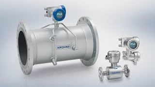
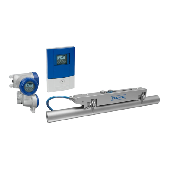
Расходомеры ультразвуковые OPTISONIC 6300 состоят из двух частей: первичного преобразователя OPTISONIC 6000 и конвертера сигналов UFC 300.
Первичный преобразователь OPTISONIC 6000 выполнен в виде разборного блока, состоящего из следующих частей: металлической направляющей с датчиками, двух узлов крепления к трубе (при помощи металлической ленты), накладной крышки.
Первичные преобразователи изготавливаются трёх видов: малые, средние, большие. Используемый тип зависит от диаметра трубы и химического состава измеряемой жидкости. Малый и средний тип отличаются друг от друга габаритными размерами, а большой первичный преобразователь состоит из двух малых первичных преобразователей.
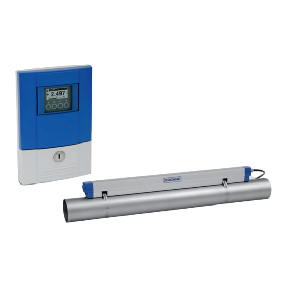
Конвертер сигналов обрабатывает полученные данные и отображает измерительную информацию на жидкокристаллическом дисплее, преобразует её в виде нормированных сигналов (на аналоговых и/или цифровых выходах), а также предназначен для питания первичного преобразователя расхода.
Расходомеры ультразвуковые OPTISONIC 6300 могут оснащаться аналоговым выходом (0 — 20) мА, частотным (импульсным) выходом (0 — 10000) Гц, дискретным выходом, дискретным входом, аналоговым входом, интерфейсами Modbus RTU, HART и Fieldbus.
а) б) в)
Рисунок 1 — Расходомеры ультразвуковые OPTISONIC 6300: а) конвертер сигналов UFC 300 F, б) конвертер сигналов UFC 300 W, в) первичные преобразователи OPTISONIC 6000.
Рисунок 2 — Конвертер сигналов UFC 300 Р.
Конвертеры сигналов выпускаются в следующих исполнениях:
— F — разнесённое исполнение. Конвертер сигналов изготовлен в корпусе полевого исполнения и соединён с первичным преобразователем сигнальным кабелем.
— W — разнесённое исполнение. Конвертер сигналов изготовлен в корпусе для настенного монтажа и соединён с первичным преобразователем сигнальным кабелем.
— P — переносное исполнение. Конвертер сигналов изготовлен в корпусе переносного исполнения из полиамида РА 12 и соединен с первичным преобразователем сигнальным.
Пломбировка расходомеров ультразвуковых OPTISONIC 6300 не предусмотрена.
Программное обеспечение
Внутреннее ПО конвертера сигналов UFC 300 выполняет функции обработки измерительной информации, отображения информации на жидкокристаллическом дисплее, а также преобразования её в виде нормированных сигналов (токовых и/или частотноимпульсных).
Уровень защиты ПО СИ от непреднамеренных и преднамеренных изменений соответствует уровню «С» согласно МИ 3286-2010.
Таблица 1
|
Наименование ПО |
Идентификационное наименование ПО |
Номер версии ПО |
Цифровой идентификатор ПО (контрольная сумма) |
Алгоритм вычисления цифрового идентификатора ПО |
|
ПО UFC 300 F, W |
ER 3.4.Х |
3.4.ХХ |
0хDC27 |
CRC16 |
|
ПО UFC 300 P |
ER 1.1.Х |
1.1.ХХ |
0хFA4B |
CRC16 |
Технические характеристики
Таблица 2
|
Наименование параметра |
Значение |
|
Диапазон измерений скорости потока, V, м/с |
от 0,1 до 20 |
|
Условный диаметр, Ду, мм |
от 15 до 4000 |
|
Толщина стенки трубы, мм, не более |
200 |
|
Температура измеряемой среды, °С |
от минус 40 до плюс 200 |
|
Пределы допускаемой относительной погрешности измерений объёмного расхода жидкости при скорости потока V>0,5 м/с и Ду >50 мм, % |
±1 |
|
Пределы допускаемой относительной погрешности измерений объёмного расхода при скорости потока V<0,5 м/с и Ду<50 мм, % |
±3 |
|
Допустимое содержание твёрдых частиц, % от объёма, не более |
5 |
|
Допустимое содержание газа, % от объёма, не более |
2 |
|
Минимальная длина прямого участка трубопровода, Ду, не менее: — до расходомера — после расходомера |
10 5 |
|
Напряжение питания переменного тока частотой 50/60 Гц, В: — стандартно — опционально (постоянный/переменный ток) — конвертор сигналов UFC 300 P |
от 100 до 230 24 встроенный аккумулятор |
|
Потребляемая мощность, Вт, не более |
12 |
|
Габаритные размеры (ДхШ*В), мм, не более: — конвертер сигналов UFC 300 F, W — конвертер сигналов UFC 300 P — первичный преобразователь OPTISONIC 6000 |
202x299x277 247x168x66 826,3x71x63 |
|
Масса составных частей расходомера, кг, не более: — конвертер сигналов UFC 300 F, W — конвертер сигналов UFC 300 P — первичный преобразователь OPTISONIC 6000 |
5,7 1,6 3,6 |
|
Условия эксплуатации: — температура окружающей среды, °С — относительная влажность, % — атмосферное давление, кПа |
от минус 40 до плюс 70 до 95 от 84,0 до 106,7 |
Знак утверждения типа
наносится на корпус конвертера сигналов при помощи наклейки и титульный лист руководства по эксплуатации типографским способом.
Комплектность
Таблица 3
|
Наименование |
Количество |
|
Расходомер |
1 шт. |
|
Методика поверки |
1 экз. |
|
Руководство по эксплуатации |
1 экз. |
Сведения о методах измерений
Сведения о методиках (методах) измерений отсутствуют.
Поверка
осуществляется по документу МП РТ 1975-2013 «ГСИ. Расходомеры ультразвуковые OPTISONIC 6300. Методика поверки», утверждённому ГЦИ СИ ФБУ «Ростест-Москва» 20 ноября 2013 г.
При поверке применяются следующие средства измерений:
— установка поверочная с диапазоном расходов от 0,1 до 200 м /ч, ПГ ±0,25 %.
Лист № 4 Всего листов 4
Нормативные и технические документы, устанавливающие требования к расходомерам ультразвуковым OPTISONIC 6300
ГОСТ 8.470-82 «ГСИ. Государственная поверочная схема для средств измерений объёма жидкости».
Техническая документация фирмы «KROHNE Altometer B.V.», Нидерланды.
Рекомендации к применению
Осуществление производственного контроля за соблюдением установленных законодательством Российской Федерации требований промышленной безопасности к эксплуатации опасного производственного объекта; осуществление торговли и товарообменных операций; выполнение работ по оценке соответствия промышленной продукции и продукции других видов, а также иных объектов установленным законодательством Российской Федерации обязательным требованиям.