40,4 Мб
Экскаваторы Твэкс ЭО-3221, ЭО-3323, ЕТ-14, ЕТ-18, ЕТ-25,
Формат: pdf
-
Год:
2008
-
Страниц:
66
-
Язык:
русский
-
Размер:
40,4 Мб
-
Категории:
Экскаваторы
4,06 Мб
Руководство по эксплуатации экскаваторов УЗТМ ЭКГ-4, УЗТМ
Формат: djvu
-
Год:
1975
-
Страниц:
161
-
Язык:
русский
-
Размер:
4,06 Мб
-
Категории:
Экскаваторы
14,5 Мб
Экскаваторы Э-302 (303, 304, 625, 652), ЭО-2621 (3111,
Формат: djvu
-
Год:
1977
-
Страниц:
389
-
Язык:
русский
-
Размер:
14,5 Мб
-
Категории:
Экскаваторы
80,9 Мб
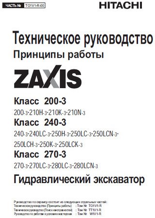
Экскаваторы Hitachi ZX200-3, ZX225-3, ZX240-3, ZX270-3:
Формат: pdf
-
Год:
2006
-
Страниц:
1826
-
Язык:
русский
-
Размер:
80,9 Мб
-
Категории:
Экскаваторы

5,14 Мб
Экскаваторы Hitachi ZX225US-3 (Zaxis 225US-3), ZX225USR-3
Формат: pdf
-
Год:
2006
-
Страниц:
309
-
Язык:
русский
-
Размер:
5,14 Мб
-
Категории:
Экскаваторы
12,1 Мб
Экскаваторы Hitachi ZX200-3 (Zaxis 200-3), ZX270-3 (Zaxis
Формат: pdf
-
Год:
2006
-
Страниц:
343
-
Язык:
русский
-
Размер:
12,1 Мб
-
Категории:
Экскаваторы

7,41 Мб
Экскаватор Hitachi ZX450 (Zaxis 450): Руководство по
Формат: pdf
-
Год:
2003
-
Страниц:
208
-
Язык:
русский
-
Размер:
7,41 Мб
-
Категории:
Экскаваторы

5,43 Мб
Экскаватор Caterpillar 345C: Руководство по эксплуатации и
Формат: pdf
-
Год:
2007
-
Страниц:
258
-
Язык:
русский
-
Размер:
5,43 Мб
-
Категории:
Экскаваторы
14,2 Мб
Руководство оператора экскаватора Volvo EC950E
Формат: pdf
-
Год:
2016
-
Страниц:
394
-
Язык:
русский
-
Размер:
14,2 Мб
-
Категории:
Экскаваторы

29,5 Мб
Экскаватор Hitachi EX1900-5: Руководство по ремонту и
Формат: pdf
-
Год:
2006
-
Страниц:
1060
-
Язык:
русский
-
Размер:
29,5 Мб
-
Категории:
Экскаваторы
93,8 Мб
Руководство по эксплуатации и обслуживанию экскаватора
Формат: pdf
-
Год:
2006
-
Страниц:
759
-
Язык:
русский, английский
-
Размер:
93,8 Мб
-
Категории:
Экскаваторы

51 Мб
Руководство по эксплуатации и обслуживанию экскаватора
Формат: pdf
-
Год:
2007
-
Страниц:
821
-
Язык:
русский, английский
-
Размер:
51 Мб
-
Категории:
Экскаваторы
9,06 Мб
Каталог запчастей экскаваторов Komatsu PC200-7, PC200LC-7,
Формат: pdf
-
Год:
2004
-
Страниц:
536
-
Язык:
английский
-
Размер:
9,06 Мб
-
Категории:
Экскаваторы

20,7 Мб
Руководство по эксплуатации и обслуживанию мини-экскаватора
Формат: pdf
-
Год:
2012
-
Страниц:
141
-
Язык:
русский
-
Размер:
20,7 Мб
-
Категории:
Экскаваторы
10,9 Мб
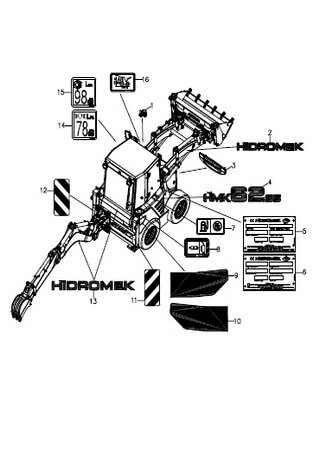
Каталог запчастей мини-экскаватора Hidromek HMK 62SS
Формат: pdf
-
Год:
2005
-
Страниц:
247
-
Язык:
турецкий, английский
-
Размер:
10,9 Мб
-
Категории:
Экскаваторы

15,9 Мб
Экскаваторы-погрузчики Hidromek HMK 102B и HMK 102S
Формат: pdf
-
Год:
2012
-
Страниц:
196
-
Язык:
русский
-
Размер:
15,9 Мб
-
Категории:
Экскаваторы
20,5 Мб
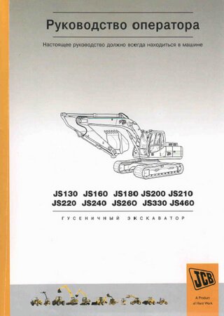
Гусеничные экскаваторы JCB JS130, JS160, JS180, JS200,
Формат: pdf
-
Год:
2001
-
Страниц:
152
-
Язык:
русский
-
Размер:
20,5 Мб
-
Категории:
Экскаваторы
5,7 Мб
Руководство по эксплуатации и обслуживанию гидравлического
Формат: pdf
-
Год:
2011
-
Страниц:
154
-
Язык:
английский
-
Размер:
5,7 Мб
-
Категории:
Экскаваторы
6,51 Мб
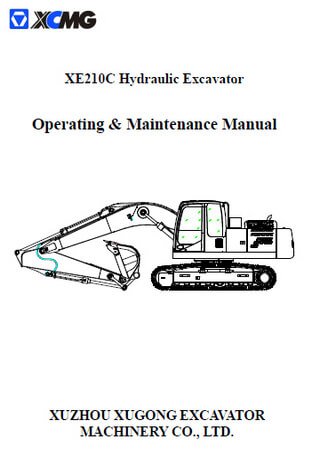
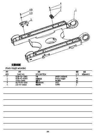
Каталог запчастей гидравлического экскаватора XCMG XE230
Формат: pdf
-
Год:
2006
-
Страниц:
102
-
Язык:
английский, китайский
-
Размер:
6,51 Мб
-
Категории:
Экскаваторы
15,3 Мб
Руководство по эксплуатации и обслуживанию гидравлических
Формат: pdf
-
Год:
2011
-
Страниц:
157
-
Язык:
испанский
-
Размер:
15,3 Мб
-
Категории:
Экскаваторы
1 2

40,4 Мб
Экскаваторы Твэкс ЭО-3221, ЭО-3323, ЕТ-14, ЕТ-18, ЕТ-25,
Формат: pdf
-
Год:
2008
-
Страниц:
66
-
Язык:
русский
-
Размер:
40,4 Мб
-
Категории:
Экскаваторы
4,06 Мб
Руководство по эксплуатации экскаваторов УЗТМ ЭКГ-4, УЗТМ
Формат: djvu
-
Год:
1975
-
Страниц:
161
-
Язык:
русский
-
Размер:
4,06 Мб
-
Категории:
Экскаваторы
14,5 Мб
Экскаваторы Э-302 (303, 304, 625, 652), ЭО-2621 (3111,
Формат: djvu
-
Год:
1977
-
Страниц:
389
-
Язык:
русский
-
Размер:
14,5 Мб
-
Категории:
Экскаваторы
80,9 Мб
Экскаваторы Hitachi ZX200-3, ZX225-3, ZX240-3, ZX270-3:
Формат: pdf
-
Год:
2006
-
Страниц:
1826
-
Язык:
русский
-
Размер:
80,9 Мб
-
Категории:
Экскаваторы
5,14 Мб
Экскаваторы Hitachi ZX225US-3 (Zaxis 225US-3), ZX225USR-3
Формат: pdf
-
Год:
2006
-
Страниц:
309
-
Язык:
русский
-
Размер:
5,14 Мб
-
Категории:
Экскаваторы
12,1 Мб
Экскаваторы Hitachi ZX200-3 (Zaxis 200-3), ZX270-3 (Zaxis
Формат: pdf
-
Год:
2006
-
Страниц:
343
-
Язык:
русский
-
Размер:
12,1 Мб
-
Категории:
Экскаваторы
7,41 Мб
Экскаватор Hitachi ZX450 (Zaxis 450): Руководство по
Формат: pdf
-
Год:
2003
-
Страниц:
208
-
Язык:
русский
-
Размер:
7,41 Мб
-
Категории:
Экскаваторы
5,43 Мб
Экскаватор Caterpillar 345C: Руководство по эксплуатации и
Формат: pdf
-
Год:
2007
-
Страниц:
258
-
Язык:
русский
-
Размер:
5,43 Мб
-
Категории:
Экскаваторы
14,2 Мб
Руководство оператора экскаватора Volvo EC950E
Формат: pdf
-
Год:
2016
-
Страниц:
394
-
Язык:
русский
-
Размер:
14,2 Мб
-
Категории:
Экскаваторы
29,5 Мб
Экскаватор Hitachi EX1900-5: Руководство по ремонту и
Формат: pdf
-
Год:
2006
-
Страниц:
1060
-
Язык:
русский
-
Размер:
29,5 Мб
-
Категории:
Экскаваторы
93,8 Мб
Руководство по эксплуатации и обслуживанию экскаватора
Формат: pdf
-
Год:
2006
-
Страниц:
759
-
Язык:
русский, английский
-
Размер:
93,8 Мб
-
Категории:
Экскаваторы
51 Мб
Руководство по эксплуатации и обслуживанию экскаватора
Формат: pdf
-
Год:
2007
-
Страниц:
821
-
Язык:
русский, английский
-
Размер:
51 Мб
-
Категории:
Экскаваторы
9,06 Мб
Каталог запчастей экскаваторов Komatsu PC200-7, PC200LC-7,
Формат: pdf
-
Год:
2004
-
Страниц:
536
-
Язык:
английский
-
Размер:
9,06 Мб
-
Категории:
Экскаваторы
20,7 Мб
Руководство по эксплуатации и обслуживанию мини-экскаватора
Формат: pdf
-
Год:
2012
-
Страниц:
141
-
Язык:
русский
-
Размер:
20,7 Мб
-
Категории:
Экскаваторы
10,9 Мб
Каталог запчастей мини-экскаватора Hidromek HMK 62SS
Формат: pdf
-
Год:
2005
-
Страниц:
247
-
Язык:
турецкий, английский
-
Размер:
10,9 Мб
-
Категории:
Экскаваторы
15,9 Мб
Экскаваторы-погрузчики Hidromek HMK 102B и HMK 102S
Формат: pdf
-
Год:
2012
-
Страниц:
196
-
Язык:
русский
-
Размер:
15,9 Мб
-
Категории:
Экскаваторы
20,5 Мб
Гусеничные экскаваторы JCB JS130, JS160, JS180, JS200,
Формат: pdf
-
Год:
2001
-
Страниц:
152
-
Язык:
русский
-
Размер:
20,5 Мб
-
Категории:
Экскаваторы
5,7 Мб
Руководство по эксплуатации и обслуживанию гидравлического
Формат: pdf
-
Год:
2011
-
Страниц:
154
-
Язык:
английский
-
Размер:
5,7 Мб
-
Категории:
Экскаваторы
6,51 Мб
Каталог запчастей гидравлического экскаватора XCMG XE230
Формат: pdf
-
Год:
2006
-
Страниц:
102
-
Язык:
английский, китайский
-
Размер:
6,51 Мб
-
Категории:
Экскаваторы
15,3 Мб
Руководство по эксплуатации и обслуживанию гидравлических
Формат: pdf
-
Год:
2011
-
Страниц:
157
-
Язык:
испанский
-
Размер:
15,3 Мб
-
Категории:
Экскаваторы
1 2
- Manuals
- Brands
- SANY Manuals
- Excavators
ManualsLib has more than 23 SANY Excavators manuals
Click on an alphabet below to see the full list of models starting with that letter:
S
S
SY115C9

Safety, Operation And Manitenance Manual
SY135C
Operation And Maintenance Manual
SY135C8
Safety, Operation And Manitenance Manual
SY135C9
Safety, Operation And Manitenance Manual
SY155H
Safety, Operation And Manitenance Manual
SY155U
Operation And Maintenance Manual
SY16C
Operation And Maintenance Manual
SY195C9
Shop Manual
SY205C9
Shop Manual
SY215C LC
Operation And Maintenance Manual
SY215C9
Shop Manual
SY225C LC
Operation And Maintenance Manual
SY225C9
Shop Manual
SY265C LC
Operation And Maintenance Manual
SY265C LR
Operation And Maintenance Manual
SY26U
Operation And Maintenance Manual
SY35U
Operation And Maintenance Manual
SY365C LC
Operation And Maintenance Manual
SY500H
Operation And Maintenance Manual
SY50U
Operation And Maintenance Manual
SY60C
Operation And Maintenance Manual
SY75
Operation And Maintenance Manual
SY95C
Operation And Maintenance Manual
Вы здесь
Руководства по эксплуатации и ремонту экскаваторов
Перейти к полной версии/Вернуться
- 1
- 2
- 3
- 4
- 5
- 6
- 7
- »
- конец
пт, 13.01.2012 — 00:27
#1
Регистрация: 29.09.2010 — 20:52
: 2114
Не в сети
Заходил: 1 год 5 месяцев назад
В этой теме предлагаю размещать руководства по эксплуатации, обслуживанию, ремонту экскаваторов. Каталоги запчастей.
Руководство по эксплуатации экскаватора Амкодор-702 ЕМ
Руководство по эксплуатации экскаватора Амкодор-702 ЕА
Руководство по эксплуатации экскаватора-погрузчика ПЭ-82
Руководство по эксплуатации экскаватора ЭО-2621А
пт, 13.01.2012 — 00:52
#2
Регистрация: 29.09.2010 — 20:52
: 2114
Не в сети
Заходил: 1 год 5 месяцев назад
пт, 13.01.2012 — 18:21
#3
Регистрация: 12.02.2010 — 06:07
: 1560
Не в сети
Заходил: 1 месяц 2 недели назад
вс, 29.01.2012 — 19:03
#4
Регистрация: 29.09.2010 — 20:52
: 2114
Не в сети
Заходил: 1 год 5 месяцев назад
чт, 16.02.2012 — 14:18
#5
Регистрация: 10.12.2011 — 20:24
: 97
Не в сети
Заходил: 2 года 11 месяцев назад
ЗДРАВСТВУЙТЕ ЕСТЬ-ЛИ У КОГО НИБУДЬ ССЫЛКА НА РУКОВОДСТВО ПО ЭКСПЛУАТАЦИИ ЭКСКАВАТОРА ЭО 2628 БОРЕКС ИЛИ КАКАЯ ДРУГАЯ ЛИТЕРАТУРА ПО ДАННОМУ ЭКСКАВАТОРУ ЗАРАНЕЕ ВАМ БЛАГОДАРЕН
пт, 09.05.2014 — 19:03
#6
Регистрация: 12.02.2010 — 06:07
: 1560
Не в сети
Заходил: 1 месяц 2 недели назад
Каталоги запчастей для экскаваторов YANMAR/
пт, 09.05.2014 — 20:00
#7
Регистрация: 12.02.2010 — 06:07
: 1560
Не в сети
Заходил: 1 месяц 2 недели назад
пт, 26.12.2014 — 18:45
#8
Регистрация: 12.02.2010 — 06:07
: 1560
Не в сети
Заходил: 1 месяц 2 недели назад
Каталоги для AIRMAN и KUBOTA. После закачки названия моделей отображаются неправильно. 152-это 15-2, 172-это 17-2 и т.д….
сб, 17.01.2015 — 18:09
#9
Регистрация: 12.02.2010 — 06:07
: 1560
Не в сети
Заходил: 1 месяц 2 недели назад
сб, 17.01.2015 — 20:00
#10
Регистрация: 12.02.2010 — 06:07
: 1560
Не в сети
Заходил: 1 месяц 2 недели назад
сб, 17.01.2015 — 20:17
#11
Регистрация: 12.02.2010 — 06:07
: 1560
Не в сети
Заходил: 1 месяц 2 недели назад
сб, 17.01.2015 — 20:24
#12
Регистрация: 12.02.2010 — 06:07
: 1560
Не в сети
Заходил: 1 месяц 2 недели назад
вт, 17.02.2015 — 08:24
#13
Регистрация: 12.02.2010 — 06:07
: 1560
Не в сети
Заходил: 1 месяц 2 недели назад
Мануалы на двигатели Yanmar.
вс, 18.01.2015 — 12:51
#14
Регистрация: 12.02.2010 — 06:07
: 1560
Не в сети
Заходил: 1 месяц 2 недели назад
Мануал для двигателя Mitsubichi S3L и L3C.
пн, 19.01.2015 — 19:16
#15
Регистрация: 12.02.2010 — 06:07
: 1560
Не в сети
Заходил: 1 месяц 2 недели назад
ср, 13.04.2016 — 17:24
#16
Регистрация: 12.02.2010 — 06:07
: 1560
Не в сети
Заходил: 1 месяц 2 недели назад
вт, 20.10.2015 — 06:03
#17
Регистрация: 12.02.2010 — 06:07
: 1560
Не в сети
Заходил: 1 месяц 2 недели назад
Мануал для TAKEUCHI TB035, TB025
пн, 26.01.2015 — 04:27
#18
Регистрация: 12.02.2010 — 06:07
: 1560
Не в сети
Заходил: 1 месяц 2 недели назад
| Вложение |
|---|
 |
ср, 28.01.2015 — 10:30
#19
Регистрация: 12.02.2010 — 06:07
: 1560
Не в сети
Заходил: 1 месяц 2 недели назад
Мануалы для двигателей KUBOTA D905-B, D1005-B, V1205-B, V1205-T-B, V1305-B. и D1403-B, D1703-B, V1903, V2203, F2803.
ср, 28.01.2015 — 17:50
#20
Регистрация: 29.09.2010 — 20:52
: 2114
Не в сети
Заходил: 1 год 5 месяцев назад
avsheff пишет:
Мануалы для двигателей


сб, 31.01.2015 — 08:33
#21
Регистрация: 12.02.2010 — 06:07
: 1560
Не в сети
Заходил: 1 месяц 2 недели назад
NiK 61 
пт, 06.02.2015 — 09:31
#22
Регистрация: 12.02.2010 — 06:07
: 1560
Не в сети
Заходил: 1 месяц 2 недели назад
Руководство по эксплуатации Bobcat 325. 328
| Вложение |
|---|
|
пт, 06.02.2015 — 17:23
#23
Регистрация: 12.02.2010 — 06:07
: 1560
Не в сети
Заходил: 1 месяц 2 недели назад
Мануал для двигателей ISUZU 3KC1, 3KR1, 3KR2.
| Вложение |
|---|
|
пн, 09.02.2015 — 07:41
#24
Регистрация: 12.02.2010 — 06:07
: 1560
Не в сети
Заходил: 1 месяц 2 недели назад
инструкция и сервис мануал для двигателей ISUZU 3LA1, 3LB1, 3LD1.
вт, 17.02.2015 — 08:30
#25
Регистрация: 12.02.2010 — 06:07
: 1560
Не в сети
Заходил: 1 месяц 2 недели назад
вт, 17.02.2015 — 18:36
#26
Регистрация: 12.02.2010 — 06:07
: 1560
Не в сети
Заходил: 1 месяц 2 недели назад
| Вложение |
|---|
|
вт, 17.02.2015 — 19:42
#27
Регистрация: 12.02.2010 — 06:07
: 1560
Не в сети
Заходил: 1 месяц 2 недели назад
Мануал KOMATSU РС25-1, РС30-7, РС40-7, РС45-1
ср, 18.02.2015 — 12:31
#28
Регистрация: 12.02.2010 — 06:07
: 1560
Не в сети
Заходил: 1 месяц 2 недели назад
Мануалы для Komatsu PC05-6F
ср, 18.02.2015 — 12:37
#29
Регистрация: 12.02.2010 — 06:07
: 1560
Не в сети
Заходил: 1 месяц 2 недели назад
Мануал для Komatsu РС12R-8, PC12R-8-HS, PC15R-8, PC15R-8-HS
ср, 18.02.2015 — 12:40
#30
Регистрация: 12.02.2010 — 06:07
: 1560
Не в сети
Заходил: 1 месяц 2 недели назад
Мануал для Komatsu PC14R-2
| Вложение |
|---|
|
ср, 18.02.2015 — 12:42
#31
Регистрация: 12.02.2010 — 06:07
: 1560
Не в сети
Заходил: 1 месяц 2 недели назад
Мануал для Komatsu PC16R-2
| Вложение |
|---|
|
- 1
- 2
- 3
- 4
- 5
- 6
- 7
- »
- конец

Самые популярные темы
- ПЛАЗМОРЕЗЫ. ПЛАЗМЕННАЯ РЕЗКА МЕТАЛЛОВ. ДУГОВАЯ СВАРКА. АРГОННАЯ СВАРКА. РАСХОДНИКИ. НОВЫЕ ТЕХНОЛОГИИ
- Руководства по эксплуатации зерноуборочных комбайнов.
- Руководства по эксплуатации и ремонту тракторов
- РУКОВОДСТВО ПО ПРЕСС ПОДБОРЩИКАМ
- Навигация в поле — параллельное вождение.
- Комбайн CLAAS Consul
- Руководства по эксплуатации и ремонту экскаваторов
- Сеялки.
- Каталоги инструкции к сельхоз технике
- Разбрасыватели удобрений
Топ20 в других разделах
Руководства по эксплуатации, обслуживанию и ремонту Отечественные экскаваторы

Заводская инструкция по эксплуатации экскаватора ЕК-14. Описывается устройство, эксплуатация и техническое обслуживание.
- Автор: —
- Издательство: Тверской экскаватор
- Год издания: 2004
- Страниц: 116
- Формат: DjVu
- Размер: 6,7 Mb
В книге описана конструкция экскаватора Э-505 и сменного рабочего оборудования с указанием изменений, введенных заводом в конструкцию экскаваторов Э-505 различных выпусков и Э-505А (Э-651). Дан анализ причин неисправностей и поломок экскаваторов при эксплуатации, способы их предупреждения, а также краткие сведения по полевому ремонту.
- Автор: А.П. Смолин
- Издательство: Машгиз
- Год издания: 1958
- Страниц: 262
- Формат: DjVu
- Размер: 3,9 Mb

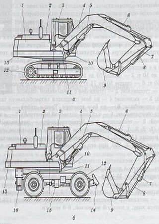
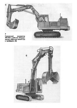
Техническое описание и инструкция по эксплуатации экскаватора одноковшового универсального гусеничного гидравлического модели ЭО-4121Б.
- Автор: —
- Издательство: Машиноэкспорт
- Год издания: 1991
- Страниц: 78 (в книжном варианте 153)
- Формат: PDF
- Размер: 10,7 Mb
Техническое описание и инструкция по эксплуатации экскаватора ЭО-4321Б содержит общие технические характеристики экскаватора, рекомендации по эксплуатации и техническому обслуживанию.
- Автор: —
- Издательство: Красный Экскаватор
- Год издания: 1993
- Страниц: 131(в книжном варианте 238)
- Формат: JPG
- Размер: 34,9 Mb

-
Contents
-
Table of Contents
-
Troubleshooting
-
Bookmarks
Quick Links
MINI EXCAVATOR
GB
MODELS
KX057-4
U48-4
U55-4
OPERATING INSTRUCTIONS
RG948-8135-6
— Original —
07/2014
Related Manuals for Kubota U48-4
Summary of Contents for Kubota U48-4
-
Page 1: Operating Instructions
MINI EXCAVATOR MODELS KX057-4 U48-4 U55-4 OPERATING INSTRUCTIONS RG948-8135-6 — Original — 07/2014…
-
Page 2
This documentation does neither extend nor restrict the contractual warranty. KUBOTA Baumaschinen GmbH reserves the right to change the information contained in this document with re- spect to future technical development without altering the basic characteristics of the excavators described herein and without amending this document. -
Page 3: Table Of Contents
Hoisting the excavator with a crane ………………….33 Transport on a flat bed trailer ……………………35 Description of the excavator ………………….37 Model overview ……………………….37 Model KX057-4, U48-4 and U55-4 ………………… 37 Dimensions………………………… 38 Dimensions KX057-4, U48-4 and U55-4……………….. 38 Specifications ……………………….40 Identification of the excavator……………………
-
Page 4
Wiper/washer system……………………51 Interior lighting ……………………..51 Fuse box ……………………….51 Tool compartment (KX057-4)………………….52 Tool compartment (U48-4 and U55-4) ………………… 52 Main battery……………………….52 Battery cut-off switch …………………….. 53 Cup holder ……………………….53 Tank filler neck and fill level monitor………………..53 Tank filler neck and fill level monitor with suction pump (optional only KX057-4)…… -
Page 5
Tables Safety instructions for starting the engine ………………..70 Starting the engine ……………………..71 Stopping the engine ……………………… 72 Observation of the displays after starting and during operation …………73 Driving the excavator ……………………. 75 Driving………………………… 76 Turning ……………………….77 During driving …………………….. -
Page 6
Tables Emergency stop functions ……………………106 Engine stop knob……………………..106 Manual lowering of the front attachments………………106 Filling up the washer system ……………………. 107 Refuelling the excavator ……………………107 Refuelling the excavator equipped with optional suction pump (only KX057-4)……. 108 Refuelling the excavator using the optional suction pump (optional only KX057-4)…… -
Page 7
Accessories ……………………..174 KUBOTA Rotary beacon ……………………174 KUBOTA Pipe safety valve ……………………174 Note on use……………………..175 KUBOTA Quick coupling systems and equipments …………….175 KUBOTA Bucket accessories…………………… 175 Replacing the bucket……………………175 Remove the bucket……………………176 Install the bucket……………………..177… -
Page 8: Abbreviations
Tables Abbreviations percent kilogramme ° degrees km/h kilometre per hour °C degree Celsius kilonewton 1/min revolutions per minute kilovolt Ampere kilowatt acc. according litre American Petroleum Institute L/min litres per minute approx. approximately sound pressure level operator’s place ASTM American Society for Testing and Materials measured sound power level metre CECE…
-
Page 9: General Symbols
Tables General symbols Warning light Swivel boom (left) Fuel indicator Swivel boom (right) Engine oil indicator Dozer up Charge indicator Dozer down Glow indicator Control lever direction Hydraulic oil Control lever direction Travel speed Rotary beacon Low speed Display selector switch Forward travel Auxiliary port enable switch Backward travel…
-
Page 10
Tables Overvoltage indicator Key indicator Anti-theft system fault indicator Wrong key indicator Insert key indicator Registration mode complete indicator Pull out key indicator Registration mode indicator Key registration indicator No overload warning indicator Voltage supply indicator 5 V Overload warning indicator Voltage supply indicator 12V Raise control lever lock indicator Lower control lever lock indicator… -
Page 11: General Information
General information Foreword These operating instructions apply only for the KUBOTA excavator models KX057-4, U48-4 and U55-4 complying with the following EC declaration of conformity (page 11). Safety instructions, the rules and regulations for the use of excavators given in these operating instructions apply to the excavators mentioned in this documentation.
-
Page 12: Date Of Issue Of The Operating Instructions
General information Date of issue of the operating instructions The date of issue of the operating instructions is printed on the bottom right of the front page of the book. Operating personnel The duties of personnel with respect to operation, servicing, repairs and safety inspections must be set forth clearly by the owner.
-
Page 13: Spare Parts
General information Spare parts Genuine spare parts can be ordered from KUBOTA dealers by stating the model and the serial # of the excavator. The item numbers for the spare parts are indicated in the spare parts catalogue.
-
Page 14: Safety Rules
Safety rules Safety rules Basic safety instructions The EC machine utilization directive (2009/104/EC) dated 16/09/2009 applies for the operation of the afore- mentioned excavator. The information in these operating instructions applies for maintenance and repairs. National rules and regulations apply where applicable. Duties, liability and warranty A basic requisite for the safe handling and problem-free operation of the excavator is the knowledge of the safety instructions and safety regulations.
-
Page 15: Safety Symbols
Safety rules The owner must ensure at his own responsibility that the safety rules are observed (page 14), unapproved use (page 16) and unauthorised operation are excluded and the approved use (page 16) is ensured and the excavator is operated in accordance with the contractual con- ditions of use.
-
Page 16: Approved Use
Safety rules Approved use The excavators specified in this operator’s manual may only be used for to loose the ground, excavating, picking up, transporting and dumping soils, rocks and other materials, for work with the dozer or with a breaker. The load may be transported largely without driving the excavator.
-
Page 17: Special Duties Of The Owner
Disposal must be undertaken in an appropriate way, according to legally prescribed pollution control and safety regulations. If you have questions about the correct disposal or storage of refuse and toxic waste, contact your KUBOTA dealer or a local waste management contractor.
-
Page 18: Safety Labels On The Excavator
Safety rules Safety labels on the excavator Keep the safety and warning symbols (labels) on the excavator clean and legible, replacing them if necessary. The positioning of the safety symbols is illustrated in the following figures. Code #: 69198-5722-0 (both sides) Do not enter the swing area.
-
Page 19
Safety rules Code #: RG109-5796-0 Not an attachment point for lifting gear. Code #: RD809-5725-0 Do not enter the manoeuvring area. Code #: TA040-4958-0 Do not touch hot parts, such as exhaust muffler, etc. Code #: RC418-5737-0 Keep away from fan and V-belt. -
Page 20
Safety rules Code #: RD809-5733-0 (both sides) Use the attachment point only for clamping the excavator securely to a transport vehicle. Code #: RD809-5795-0 (both sides) For information about loosening the crawler, consult the operating instructions. Code #: RD809-5714-0 Emergency exit. -
Page 21
Safety rules Code #: RB419-5793-0 Risk of injury through windshield getting out of place. Always lock the windshield. Code #: RD809-5743-0 Caution: Always fasten the seat belt to avoid an increased risk of injury. Code #: 69198-5784-0 Attention: Read the operating instructions and make sure that the instructions have been under- stood before starting or operating the excavator. -
Page 22
Safety rules Code #: RA028-5724-0 Radiator: Risk of burns. Code #: RB238-5736-0 Diesel fuel only, no open fire. Code #: RD451-5748-0 Fill level monitor when refuelling. -
Page 23
Safety rules Code #: RD359-5726-0 Operation of the suction pump. (Optional KX057-4) Code #: RD809-5745-0 Do not touch hot parts, such as exhaust muffler, etc. -
Page 24
Safety rules 20) Code #: RD359-5747-0 KX057-4 20) Code #: RD459-5747-0 U48-4 20) Code #: RD559-5747-0 U55-4… -
Page 25
Safety rules 21) Code #: RH849-5749-0 Risk of accidents by exceeded load when lifting! When exceeding the nominal load, a beep sounds and a warning light illuminates. Turn on overload warning function before starting a lifting opera- tion! -
Page 26: Safety Devices
Safety rules Safety devices Before starting the excavator, all safety devices must be installed properly and operational. No manipulation of safety devices, e.g. the shorting of limit switches, is allowed. Protective devices may only be removed after the excavator is standing still and the engine is stopped and secured against restarting (starter switch in STOP position and key removed).
-
Page 27: Protective Structure Canopy And Cab
The seat belt must be fastened while the excavator is being operated. Do not make any structural changes to the protective structure. In the event of damage, please contact your KUBOTA dealer. (Do not repair!) Never operate the excavator without the protective structure.
-
Page 28: Pipe Safety Valve
Any manipulation can result in substantial personal injuries, even death, and is therefore strictly for- STOP bidden. The manipulation and repair of the pipe safety valves is forbidden. They may only be replaced by your KUBOTA dealer as a kit. Overload warning function An overload warning function informs the operator immediately if there is an overload.
-
Page 29: Hazards Coming From The Hydraulic System
Safety rules Hazards coming from the hydraulic system If hydraulic oil gets into the eyes, rinse them immediately with clear water and subsequently seek medical aid. Do not allow hydraulic oil to contact the skin or clothing. Skin parts which may have come in contact with hydraulic oil must be washed with water and soap immediately, if possible.
-
Page 30
Safety rules A fire extinguisher is not included in the basic equip- ment of the machine. -
Page 31: Recovery, Loading And Transport
Recovery, loading and transport Recovery, loading and transport Safety rules for recovery For recovery of the excavator, a towing vehicle of at least the same weight class as the excavator must be used. A tow bar must be used for the recovery. If a tow rope is used, an additional vehicle to brake the excavator must also be attached.
-
Page 32: Safety Rules For Transport
Recovery, loading and transport Safety rules for transport The ramps must have a sufficient load capacity for bearing the weight of the excavator. They must be placed securely on the transport vehicle and fastened. Support the loading area at the rear of the transport vehicle with sufficiently dimensioned supports. The ramps must be wider than the track of the excavator and have footboards on the side.
-
Page 33: Recovery
1 (mm) l 2 (mm) Bring the boom in line with the longitudinal axis of the swivel KX057-4 < 51 1680 4280 frame. U48-4 < 55 1250 3770 U55-4 < 57 1150 3805 Completely extend the boom cylinder, arm cylinder and bucket cylinder.
-
Page 34
Recovery, loading and transport Attach the lifting gear with shackles to the lifting eyes (1) on each side of the dozer. Attach the lifting gear with shackles to the lifting eyes (1) on each side of the boom. As soon as the lifting gear is attached to the excavator, press cloths between lifting gear and excavator to protect the excavator. -
Page 35: Transport On A Flat Bed Trailer
Recovery, loading and transport Transport on a flat bed trailer Adhere to the safety rules (page 14) and the safety STOP rules for transport (page 32). Place the loading ramps on the transport vehicle at an angle of 10° to 15°. Observe the track width. Safely attach the ramps to the transport vehicle to make sure they cannot slide while driv- ing upwards.
-
Page 36
Recovery, loading and transport For safe attachment, fully crowd the arm and bucket and lower the boom until the bucket linkage touches the loading area. Secure the chains and the dozer with beams (2). Secure the excavator against sliding on the transport vehicle with chocks or chains (1) (note the vehicle weight). -
Page 37: Description Of The Excavator
Description of the excavator Description of the excavator Model overview The excavator is available in three models KX057-4, U48-4 and U55-4. Model KX057-4, U48-4 and U55-4…
-
Page 38: Dimensions
Description of the excavator Dimensions The dimensions of the models KX057-4, U48-4 and U55-4 can be found in the following illustrations including ta- bles. Dimensions KX057-4, U48-4 and U55-4…
-
Page 39
Description of the excavator All dimensions in mm with original KUBOTA bucket and rubber crawlers KX057-4 1960 5820 4160 3890 3070 1270 4250 6260 1960 5665 4005 3630 2830 1270 4235 6025 2550 1960 6130 5520 1830 2420 2550 1960… -
Page 40: Specifications
Description of the excavator Specifications Following are the specifications for these series. KUBOTA Excavator Model name KX057-4 Type Rubber crawler Steel crawler Machine weight* 5470 5570 Operating weight** 5545 5645 Volume (SAE/CECE) m³ 0.17/0.15 Bucket (KUBOTA) Width with teeth Water-cooled four-cylinder…
-
Page 41
Description of the excavator KUBOTA Excavator Model name U48-4 Type Rubber crawler Steel crawler Machine weight* 4700 4800 Operating weight** 4775 4875 Volume (SAE/CECE) m³ 0.14/0.12 Bucket (KUBOTA) Width with teeth Water-cooled four-cylinder die- Type sel engine Model name KUBOTA V2607-DI-E3-BH… -
Page 42
Description of the excavator KUBOTA Excavator Model name U55-4 Type Rubber crawler Steel crawler Machine weight* 5325 5425 Operating weight** 5400 5500 Volume (SAE/CECE) m³ 0.16/0.13 Bucket (KUBOTA) Width with teeth Water-cooled four-cylinder Type diesel engine Model name KUBOTA V2607-DI-E3-BH… -
Page 43: Identification Of The Excavator
Description of the excavator Identification of the excavator The type plate of the excavator is located at the front of the swivel frame. The owner should enter the stamped data in the field on the back of the front cover. CE marking Serial # Max.
-
Page 44: Engine Number
Description of the excavator Engine number The engine number (1) is affixed to the engine block. Equipment The standard equipment of the excavator can be enhanced by optional equipment (accessories). Standard equipment This model has the following standard equipment: Operating instructions with protective cover Spare parts catalogue Filter wrench Grease gun…
-
Page 45: Assembly And Functions
Assembly and functions Assembly and functions Component overview Swivel frame Boom cylinder Track frame Bucket Rear view mirror Bucket linkage Operator’s place Auxiliary port connectors Cab door Bucket cylinder tank filler neck Drive sprocket Arm cylinder Crawler Boom Idler Working light (boom) Dozer Working lights (cab) Dozer cylinder…
-
Page 46: Operator’s Place
Assembly and functions Operator’s place The operator’s place is located in the middle of the cab. It includes the following control elements: Left control console Drive levers and control pedals Right control console Operator’s seat Left control console The left control console includes the following components: Control lever lock Rocker switch for the auxiliary port 2 Wrist rest…
-
Page 47: Drive Levers And Control Pedals
Assembly and functions Left control lever The left control lever is used to move the swivel frame and the arm. The figure, in conjunction with the following table, shows the functions of the left control lever. Position of control lever Movement Arm crowd Arm dump Swivel frame to the left…
-
Page 48: Right Control Console
Assembly and functions Right control console The right-hand control console contains the following components: Rocker switch for the auxiliary port 1 One way hold switch Travel speed button Dozer control lever Starter switch Potentiometer for the adjustment of the engine speed Heating and air-conditioner control (optional) Wiper/washer switch Engine stop knob…
-
Page 49
Assembly and functions Starter switch The starter switch serves as the master switch for the entire machine and as switch for pre-glowing and start- ing the engine. Potentiometer for the adjustment of the engine speed The operator can use this potentiometer to set the engine RPM to any desired speed. Heating and air-conditioner control (optional) Operate the heater and the air-conditioner using the heating and air-conditioner control (optional). -
Page 50: Display And Control Unit — Description
Assembly and functions Display and control unit — description The display and control unit’s switches are multifunctional and are also used to navigate the display menu. You will find detailed descriptions of the individual functions in the respective chapters. Menu button The menu button activates the navigation function for the display menu.
-
Page 51: Other Equipment To Be Found At The Machine
Assembly and functions Other equipment to be found at the machine Other equipment located at and around the machine is described below. Wiper/washer system The front window is provided with a wiper/washer system. The sys- tem is operated with the wiper/washer switch (1). Interior lighting An interior light (1) is located on the left side of the cab roof.
-
Page 52: Tool Compartment (Kx057-4)
The tool compartment (1) is located on the right-hand side of the ve- hicle before the side cover. Tool compartment (U48-4 and U55-4) The tool compartment (1) is located on the right-hand side of the ve- hicle under the side cover.
-
Page 53: Battery Cut-Off Switch
Assembly and functions Battery cut-off switch The battery cut-off switch (1) can be used to cut off the main power circuit. The battery cut-off switch is on the right vehicle side under the side cover. Cup holder There is a cup holder (1) in the right control console. Tank filler neck and fill level monitor The tank filler neck (1) is located at rear left-hand side (not if option- al suction pump is equipped, page 54) and it closed with a lockable…
-
Page 54: Tank Filler Neck And Fill Level Monitor With Suction Pump (Optional Only Kx057-4)
Assembly and functions Tank filler neck and fill level monitor with suction pump (optional only KX057-4) The excavator can be equipped with an optional suction pump (2). With this equipment, the suction pump, the tank filler neck (3) and the fill level monitor (1) are located below the left service cover (4) (only if equipped with optional suction pump).
-
Page 55
Assembly and functions The air is drawn in through the cabin filter (1) as fresh air via the air intake to the right of the cabin (3) or as recirculated air in the cabin. With the lever (21) the air intake can be switched between recircu- lated air (A) and fresh air (B). -
Page 56: Engine Compartment
Assembly and functions Engine compartment The engine compartment (figure below) is positioned at the rear of the swivel frame; it is covered by a lockable hinged cover. Air filter Oil dipstick Fuel injection pump Oil filler opening Filter indicator Starter Engine Fuel filter Coolant expansion reservoir…
-
Page 57: Hydraulic System
Assembly and functions Hydraulic system All controls enable the functions via a hydraulic oil pilot control circuit. The accumulator allows the boom and the arm to be lowered in case of an engine failure. The hydraulic oil tank contains the suction filter and the return filter. Using the return change valve for the auxiliary port you can activate a direct return flow to the hydraulic oil tank while auxiliary port 1 is in operation.
-
Page 58: Operation
Operation Operation Safety rules for operation The safety instructions (page 14) must be followed. The excavator may only be operated according to its approved use (page 16). The excavator may only be operated by trained personnel (page 12). Do not operate the excavator when under the influence of drugs, medication or alcohol. Stop operation when getting tired.
-
Page 59: Safety For Children
Operation Safety for children Children are normally attracted to machines and their normal operation. If children are in the vicinity of the machine and are not at a suitable distance and in the field of vision of the operator, this can STOP lead to serious accidents or even death of the children.
-
Page 60: Working In The Vicinity Of Overhead Power Lines
Operation Working in the vicinity of overhead power lines When working with the excavator in the vicinity of overhead power lines and tram lines, a minimum distance as specified in the following table must be maintained between the excavator and its attachments and the power line. Rated voltage [V] Safe distance [m] up to 1 kV…
-
Page 61: Initial Operation
Operation Initial operation Before initial operation, the excavator must first be checked visually for external transit damages and checked if the shipped equipment is complete as ordered. Check fluid levels as described in the «Maintenance» section (page 126). For a description of all operation features refer to the «Operating the excavator» section (page 64) as well as the following sections.
-
Page 62: Setting The Time
Operation Setting the time Turn the starter switch to the RUN position. Press button 1. The user menu appears in the display. Press button 2 or 3 until «Clock Set» is selected in the display. Press button 5 to confirm. Date and time appear in the display.
-
Page 63: Date And Time Display Format
Operation Date and time display format Time can be displayed in the 12- or 24-hour format, while the date format can be changed to day, month, year. Turn the starter switch to the RUN position. Press button 1. The user menu appears in the display. Press button 2 or 3 until «Various Settings»…
-
Page 64: Running-In Of The Excavator
Operation Running-in of the excavator During the first 50 hours of operation, the following points should be adhered to in all cases: Warm up the excavator at an average engine speed and with a low load; do not let it warm up at idling position. Do not overload the excavator.
-
Page 65: Checking The Coolant Level
Operation Checking the coolant level Check the coolant level in the expansion reservoir (1). The fluid level must be between FULL and LOW. Do not open the radiator cap. STOP If the coolant level is below the LOW mark, refill cool- ant (page 131).
-
Page 66: Checking The V-Belts
Operation Checking the V-belts The engine must be switched off and the key removed! STOP Do not attempt to grasp rotating or moving parts. Press in the V-belt (1) at position «A»; the belt must give way for 7 to 9 mm (at a pressure of 6 to 7 kg). Adjust the V-belts if nec- essary (page 133).
-
Page 67: Checking The Oil Level Of The Hydraulic System
Operation Checking the oil level of the hydraulic system Operate the boom, arm, bucket and boom swing mechanism so that all hydraulic cylinders are extended half way. Lower the dozer onto the ground. See the «Placing out of operation» section (page 97). Check the oil level in the sight glass (1).
-
Page 68: Checking The Electric Cables And Connections
Operation Checking the electric cables and connections Check all accessible electric cables, connectors and connections for condition and security. Repair or replace damaged parts. Check the fuse box and fuse holders for oxidation and dirt, clean if necessary. Checking fuel level, coolant temperature and time The following function can be carried out when the key is not in the starter switch.
-
Page 69: Adjusting The Operator’s Seat
Operation Adjusting the operator’s seat Adjust the operator’s seat so that fatigue-free and comfortable working is possible. It should be pos- sible to operate all controls safely. Horizontal seat adjustment (seat stand-off) Pull the horizontal seat adjustment lever (4) up and move the seat to the desired position by moving it forward or back, then release the lever.
-
Page 70: Seat Belt
Operation Seat belt Buckle up (figure above/1). Check that the seat belt is fastened tightly. Do not operate the excavator without the seat belt fastened. STOP Rear view mirrors adjustment Check the adjustment of the rear view mirrors. If necessary, adjust the mirrors until the optimum sight is en- sured.
-
Page 71: Starting The Engine
Operation Starting the engine Place the potentiometer (1) to the centre position between . The AUTO IDLE switch (2) is switched off. The indicator does not light up. Insert the key into the starter switch (3) and turn it to the RUN position.
-
Page 72: Stopping The Engine
Operation Turn the starter switch to the START position and hold it there until the engine has started. Release the starter switch. Lower the left control console and make sure that the control lever lock engages. Let the engine run at middle speed until the operating temperature has been reached. After the engine has reached its operating temperature, set the engine speed required for operation: Move the potentiometer towards until the engine reaches the required speed.
-
Page 73: Observation Of The Displays After Starting And During Operation
Operation Observation of the displays after starting and during operation The operator must observe the display indicators and displays after starting and during operation. The warning light (1) flashes red when a system fault or technical malfunction occurs. Stop the engine im- mediately! The warning light flashes yellow when the system issues a warning.
-
Page 74
Operation If the coolant temperature is too high, cool down the engine by changing into idle. The display message as in the figure on the right appears. Allow the machine to idle for five minutes before switching off the engine! Check the level of the coolant in the expansion tank. -
Page 75: Driving The Excavator
Operation Also stop the engine immediately if the engine speed rises or drops suddenly, abnormal noises are heard, the excavating devices do not respond to the control lever as expected or the exhaust fumes are black or white. When the engine is still cold, white smoke for a short time is normal. Driving the excavator Adhere to the general safety rules (page 14) and the safety rules for operation (page 58).
-
Page 76: Driving
Operation Approach overhangs and edges of ditches carefully as they could cave in. Drive slowly downhill, do not allow the vehicle speed to in- crease uncontrollably. Close the cab door. When driving, the bucket should be approx. 200 to 400 mm (A) over the ground (see figure).
-
Page 77: Turning
Operation Two audible signals will sound and the indicator (1) will come up. Pressing the travel speed button again switches back to normal speed and only one signal will sound. Do not drive fast on muddy or uneven terrain, also if another control is operated (e.g. turning the swiv- STOP el frame).
-
Page 78: From A Standing Position
Operation From a standing position Leave the right drive lever in neutral, push the left drive lever forward. In this case, the turning radius is determined by the right track. (A) The excavator makes a right turn. Turning on the spot Do not make a turn on the spot with the travel speed STOP button actuated.
-
Page 79: Driving Uphill And Downhill
Operation Driving uphill and downhill Exercise extreme caution when driving up and down a STOP slope. Do not use the travel speed button. When driving on gradients, raise the bucket approx. 200 to 400 mm (A) above the ground (see figure). When driving on gradients, let the bucket slide over the ground if the terrain allows it.
-
Page 80: Making Sharp Turns
Operation Making sharp turns On streets with a high-friction tarmac, e.g. concrete, do not make sharp turns. Protecting the crawler against salt Do not work with the machine on the seashore. (The salt will cause the steel insert to corrode.) Operating the controls during excavation work Always observe the following safety instructions when working with the excavator.
-
Page 81: Note On Using Wider And Deeper Buckets
Operation Note on using wider and deeper buckets When using a wider or deeper bucket, take good care when swinging or retracting the front attachments to make sure that the bucket does not hit the cab. Operating the dozer When working with the dozer, operate both drive le- vers with the left hand and the dozer control lever with the right hand.
-
Page 82: Overview Of Control Lever Functions (Standard Setting)
Operation Overview of control lever functions (standard setting) The figure shows, in connection with the following table, the func- tions of the left and right control levers. Control lever Movement Right control lever Lower boom Raise boom Bucket crowd Bucket dump Left control lever Arm crowd Arm dump…
-
Page 83: Operating The Arm
Operation Operating the arm To dump the arm, push the left control lever forward (figure/ ). To crowd the arm, pull the left control lever back (figure/ ). The arm moves as shown in the figure.
-
Page 84: Operating The Bucket
Operation Operating the bucket To crowd (digging) the bucket, move the right control lever to the left (figure/ ). To dump (empty) the bucket, move the right control lever to the right (figure/ ). When crowding the bucket, take care that the teeth do not hit the dozer.
-
Page 85: Swivelling The Swivel Frame
Operation Swivelling the swivel frame No person is allowed to stand in the swivel area during STOP the movement. Swivel carefully to avoid any contact of the front at- tachments with adjacent objects. To turn anticlockwise, move the left control lever to the left (fig- ure/ ).
-
Page 86: Operating The Auxiliary Ports
Operation Operating the auxiliary ports Implements are operated using the auxiliary ports. Only implements approved by KUBOTA may be used. The implements must be operated in accord- STOP ance with the operating instructions supplied with them. With the use of a breaker or another attachment for demolition work, where material (e.g. asphalt) is…
-
Page 87: Auxiliary Port 1
Operation Auxiliary port 1 The following figure illustrates the auxiliary port 1 and auxiliary port 1 rocker switch (3) connectors. The proportional control enables you to smoothly con- trol the implement speed. Example: If you move the rocker switch half a turn to the left, the implement moves at half speed.
-
Page 88: One Way Hold Operation
Operation One way hold operation For one way hold operation, the return change valve has to be set to the direct return flow position (page 94). Activate the operation setting for the «one way flow». Switching on Briefly push the one way hold switch (1). The oil flows on one side to auxiliary port 1 (2) on the left side of the arm.
-
Page 89
Operation Select the mode of operation Mode 0 Mode 1 Mode 2 Mode 3 Auxiliary port not active Flow rate index Icon Flashing Flashing Flashing Auxiliary port enable switch Flow in one direction Auxiliary port 1 Not active Max. flow rate Limited flow volume (oil to connector 2 only) Auxiliary port 2… -
Page 90: Flow Rate Setting
Operation Flow rate setting Suppose the same implement has to be attached to a different excavator. Even when using identical flow rate set- tings for the other excavator, the working speed may differ. For each excavator, you need to individually adjust the flow rate settings.
-
Page 91
Operation You can select the following symbols: Auxiliary port (default) Brush cutter Rotary grapple Grapple Auger Dipper bucket Breaker Tilt bucket Deactivated There is no relationship between the icons and the flow control settings. Select icons to suit the images of at- tachments to be connected. -
Page 92
Operation Press button 1 to complete the settings and return to the normal display. It is possible that some implements will not be activated even when the bar graph is not at its lowest level. Even when the bar graphs are at the same height, it is possible that the implements will not operate identically. -
Page 93
Operation Setting the maximum flow rate Lower the control lever lock Is the control le- (UNLOCKED po- ver lock locked? sition) Is the Start the engine engine running? Selecting the operating mode Selection of symbols Moving the arrow marking Setting the maximum flow rate… -
Page 94: Return Change Valve For Direct Return Flow
Operation Return change valve for direct return flow The change valve has two settings. When «direct return flow» is enabled, the return flow is directed from the implement to the hydraulic oil tank via the return filter. The return flow is directed via the right auxiliary port 1 connector at the arm on- When «indirect return flow»…
-
Page 95: Pressure Relief Of The Hydraulic System
Operation Pressure relief of the hydraulic system Lower front attachments and dozer completely. Turn the starter switch to the STOP position. Wait until the engine has come to a standstill. Turn the starter switch to the RUN position. Do not start the engine! Lower the left control console (1) and make sure that the con- trol lever lock (2) engages.
-
Page 96
Operation You will see the setting of the flow rates in the display. The bar height «A» shows the flow rate at the respective auxiliary port con- nectors (1, 2, 3 and 4). If the bar graph is set to the lowest level (as shown in connector 3, no bar obvious), flow is blocked and there is no oil flow. -
Page 97: Placing Out Of Operation
Operation Placing out of operation Park the excavator in such a way that it can not move and is secured against unauthorised use. STOP Drive the excavator onto level ground. Extend the hydraulic cylinders as follows: Boom: Half-extended Arm: Half-extended Bucket: Half-extended Dozer:…
-
Page 98: Operating The Heating And Air-Conditioner System (Optional)
Operation Operating the heating and air-conditioner system (optional) All the heating and air-conditioner system operations described below must be carried out while the engine is running. Heating the cab Set the temperature control (1) to the desired position. Blue ! Cold Red ! Warm Set the blower switch (2) to position 1, 2 or 3.
-
Page 99: De-Icing Or Demisting The Windows
Operation De-icing or demisting the windows Proceed as follows to de-ice the windows or clean them of conden- sation: Set the temperature control (1) to the «Warm» position. Blue ! Cold Red ! Warm Set the blower switch (2) to the 3 position. Use the air-conditioner switch (3, optional) to switch the system on.
-
Page 100: To Turn On The Washer System
Operation To turn on the washer system The washer system can be operated irrespective of whether the wiper is on or off. If the wiper is on: Press the switch (1) to the WIPER/WASHER position again and hold it down. If the wiper is off: Press the switch (1) to the OFF position and hold it down.
-
Page 101: Operating The 12 V Plug
Operation Operating the 12 V plug Open the cover cap (1) and put the load into the 12 V plug. The rated current of the connected load must not ex- ceed 10 A. Opening and closing the cab door Opening the cab door from outside Unlock the cab door at the door lock (3).
-
Page 102: Opening The Cab Door From The Inside
Operation Opening the cab door from the inside Pull the release lever (1) and open the door. If the cab door is not closed again right away, lock the door at the cab wall. Opening and closing the windows Front window Always lock the front window.
-
Page 103: Side Window
Operation Side window Pull the grip (1) to release the lock and pull side window open to the rear or to the front. To close the side window, slide it forward or backward until the lock snaps in at the window frame. Operating the working light (boom) The starter switch is in the RUN position.
-
Page 104: Cold Weather Operation
Operation Cold weather operation Operating the excavator at an ambient temperature below 5 °C is regarded as cold weather operation. Necessary preparations prior to the winter season If necessary, replace the engine oil and hydraulic oil with those of the viscosities specified for winter. Only use regular diesel fuel with winter additives.
-
Page 105: Jump-Starting The Excavator
Operation Jump-starting the excavator Only a vehicle or starting device with a 12 V power supply may be used. STOP The operator must remain seated on the operator’s place, the battery jumper cables must be con- nected by a second person. Make the battery accessible, and remove the positive terminal cover.
-
Page 106: Emergency Stop Functions
Operation Emergency stop functions In case of emergency, you can switch off the engine and lower the boom manually. Engine stop knob If the engine cannot be stopped with the key, it can be stopped man- ually. To stop the engine, pull the knob (1) until the engine stops. After the engine has stopped, push in the knob.
-
Page 107: Filling Up The Washer System
Operation Filling up the washer system Open the cap (1) of the washer system reservoir (2) and add water or a cleaning agent. In winter, use a cleaning agent with antifreeze. Refuelling the excavator When refuelling the excavator, smoking, an open flame, or other sources of ignition are not allowed. The danger zone has to be clearly marked with signs.
-
Page 108: Refuelling The Excavator Equipped With Optional Suction Pump (Only Kx057-4)
Operation Refuelling the excavator equipped with optional suction pump (only KX057-4) Stop the engine. Open the left service cover (page 114). Remove the filler cap (1) by turning it anticlockwise. Fill diesel fuel up to the base of the filler neck. Screw on the filler cap and close the service cover.
-
Page 109: Fill Level Monitor When Refuelling
Operation Switch on the suction pump. To do this, press the black button (1). Upon reaching the maximum fill level, the suction pump will automatically switch off. To switch it off manually, press the red button (2). Screw on the filler cap and close the service cover. Fill level monitor when refuelling The momentary fill level during refuelling can be determined by means of an acoustic signal.
-
Page 110: Bleeding The Fuel System
Operation Bleeding the fuel system If the excavator fuel tank was run empty or the water separator was cleaned, the fuel system must be bled. To bleed the fuel system, move the starter switch to the RUN position. The electrical fuel pump will bleed the fuel system automatically within approx.
-
Page 111: Fuse Layout Of The Fuse Box
Operation Remove the defective fuse from the fuse box (1) and replace it. The fuse layout is shown in the figure below. Fuse layout of the fuse box Cab working lights AUTO IDLE engine Boom working light Horn switch Horn Control unit Interior lighting Rotary beacon…
-
Page 112: Main Fuses
Operation Main fuses Remove the defective main fuse from the main fuse box (1) and replace it. Fuse layout: Not assigned Alternator (80 A) Main fuse (50 A) Engine cut-off switch/cab relay (fan motor) (50 A) Operating the battery cut-off switch In order for the excavator to be operated, the battery cut-off switch (1) must be in the ON position.
-
Page 113: Opening/Closing The Side Cover
Operation Secure the engine compartment cover with the catch (1). Make sure that the catch has snapped into place prop- erly. If the engine cover is unexpectedly slammed shut, STOP for example by another person or by the wind, serious injury could result.
-
Page 114: Opening/Closing The Tool Compartment (Kx057-4 Only)
Operation Opening/closing the tool compartment (KX057-4 only) Open the side cover (page 113). Tilt the lid (1). To close, lower the lid again and close the side cover. Opening/closing the service covers Opening/closing the front service covers Insert the key in the lock (1) of the cover (2) and turn it clock- wise.
-
Page 115: Replacing The Bucket
Operation Replacing the bucket When replacing the bucket, make sure to wear an eye protection, a helmet and protective gloves. STOP During attaching and detaching, chippings and burrs may occur at the bolts or bushings. These may STOP cause severe injuries. Never use your fingers for the alignment of the components (linkage, bucket, arm).
-
Page 116: Red Key (For Registering)
Use only the special KUBOTA key ring. Other key rings can lead to signal failures between the key and starter switch, and the engine can possibly not start or a key registration cannot be performed.
-
Page 117: Registering A Black Key For The Machine
Operation If you attempt to register a fifth black key, the display will show the «Stop Register» message and registration cannot be carried out. Stop register Registering a black key for the machine Register a black key only under the following conditions: Make sure that there are no persons within the excavator’s working area.
-
Page 118
Operation Pull out the red key. The display shows the «Insert key» message. Insert black key into the starter switch. Do not turn the key at this point. If the key is in the RUN position, turn it back to the STOP position. Insert key After a brief moment, the display shows the «Pull out black key»… -
Page 119: Troubleshooting
Troubleshooting Troubleshooting The troubleshooting section includes only malfunctions and incorrect operations which must be remedied by the operator. Any other malfunctions may only be eliminated by trained personnel. The troubleshooting must be per- formed with the aid of the troubleshooting table. In order to locate a malfunction, first look in the MALFUNCTION column for the corresponding excavator malfunction.
-
Page 120: Troubleshooting: Operation
Troubleshooting Troubleshooting: Operation MALFUNCTION POSSIBLE CAUSE REPAIR Operation Exhaust gas colour very black Air filter restricted Check, clean and replace the air fil- ter (page 137). Insufficient engine power Air filter restricted Check, clean and replace the air fil- ter (page 137). Fuel filter restricted or water in fuel Check the water separator for water system…
-
Page 121: Troubleshooting: Display Indications
If the machine develops a fault, one of the following messages will appear on the display. In the event of problems please inform your KUBOTA dealer immediately. If the information symbol (i) appears in the display, you can view detailed information by pressing the information button. Inform your KUBOTA dealer which messages appeared in the display. Display Problem/Error…
-
Page 122
Fuel sensor error The fuel sensor has de- Press the display selector Inform your KUBOTA veloped a fault; the fuel switch (button 5) to return to dealer immediately. gauge does not appear the default display. -
Page 123
When the V-belt is OK, let the not go out, inform engine run until indicator goes your KUBOTA dealer out. immediately. Oil pressure too low The engine oil pressure Stop the engine immediately. Inform your KUBOTA is too low. -
Page 124
2 will not dealer immediately. function. Periodic This message means Operate the machine as usual. Ask your KUBOTA check soon (notice) that the regular service dealer about the rel- is due shortly. evant parts. Run the maintenance proce- dure. -
Page 125
Display Problem/Error Preliminary Measure Solution Period check This message means The machine can be operated Ask your KUBOTA passed (warning) that the regular service but service must be carried out dealer about the rel- is due. urgently. evant parts. Run the maintenance proce- dure. -
Page 126: Maintenance
A careful maintenance of the excavator will guarantee functional safety and longer service life. Neglect of the servicing will void the warranty and any liability by KUBOTA. Only use spare parts that are recommended by the manufacturer. Non-approved spare parts of inferior quality or wrong classification result in an increased risk of accidents.
-
Page 127: General Maintenance Chart: 50 To 500 Hours Of Operation
Maintenance General maintenance chart: 50 to 500 hours of operation Operator servicing Elapsed hours of operation General maintenance Interval Page Check the fuel level daily Check the coolant level daily Checking the engine oil level daily Check the hydraulic oil level daily Grease the bucket bolt and daily…
-
Page 128: General Maintenance Chart: 550 To 1000 Hours Of Operation
Maintenance General maintenance chart: 550 to 1000 hours of operation Operator servicing Elapsed hours of operation General maintenance 1000 Interval Page Check the fuel level daily Check the coolant level daily Checking the engine oil level daily Check the hydraulic oil level daily Grease the bucket bolt and daily…
-
Page 129: Servicing Maintenance Chart: 50 To 500 Hours Of Operation
Maintenance Servicing maintenance chart: 50 to 500 hours of operation Servicing by skilled personnel or KUBOTA dealer Elapsed hours of operation * Servicing Interval Page Check the coolant hoses and » » 250 h hose clamps » » Check and adjust the V-belt…
-
Page 130: Servicing Maintenance Chart: 550 To 1000 Hours Of Operation
Maintenance Servicing maintenance chart: 550 to 1000 hours of operation Servicing by skilled personnel or KUBOTA dealer Elapsed hours of operation Servicing 1000 Interval Page Check the coolant hoses and » » 250 h hose clamps » » Check and adjust the V-belt…
-
Page 131: Cleaning The Excavator
Maintenance Cleaning the excavator Before cleaning, shut down the engine and secure it against starting. STOP If a steam cleaner is used for cleaning the excavator, do not direct the steam jet at electric compo- nents. Do not direct a water jet into the intake opening of the air filter. Do not clean the excavator with inflammable liquids.
-
Page 132: Cleaning The Radiators And The Condenser
Maintenance Do not open the radiator cap while the engine is still STOP hot, risk of scalding. Open the side cover (page 113). Remove the radiator cap (1) by turning it anticlockwise. The coolant level should be at the lower mark of the filler plug; if not, add coolant.
-
Page 133: Checking, Adjusting And Replacing The V-Belts
Maintenance Checking, adjusting and replacing the V-belts Adjusting the V-belts Open the engine compartment cover (page 112). Check the V-belt (page 66). Remove the mounting screws (2). Tighten the V-belts by adjusting the tension roller (1). Press in the V-belt (3) at position «A». The V-belt must give way for approx.
-
Page 134: Replacing The Coolant
Maintenance Replacing the coolant Drain the coolant only when the engine is cold. STOP Total cooling system capacity: 8.1 L Open the engine compartment and side cover (page 112). Remove the radiator cap (1) by turning it anticlockwise. Open the central coolant drain plug (1) and drain the coolant completely.
-
Page 135: Replacing The Engine Oil And Oil Filter
Maintenance Replacing the engine oil and oil filter Open the engine compartment cover (page 112). The engine oil change must be carried out while the engine is warm. Caution: The engine oil and the oil filter are very hot ! risk of scalding. STOP Place an oil pan with a capacity of about 15 L under the engine oil drain.
-
Page 136: Filling The Engine Oil
Maintenance Filling the engine oil Filling capacity: 9.0 L Remove the oil filler cap (2) and fill engine oil. See the «Recom- mended lubricants» section (page 159). Screw in the oil filler cap. Start the engine (page 71). The engine oil pressure indicator must go out as soon as the engine has started.
-
Page 137: Checking, Cleaning And Replacing The Air Filter
Maintenance Checking, cleaning and replacing the air filter If the excavator is operated in a particularly dusty envi- ronment, the air filter must be checked more often. Open the engine compartment cover (page 112). Open the clips (2) and remove the cover (1). Pull the outer filter element (1) out of the air filter case (3) and check it for dirt.
-
Page 138: Replacing The Fuel Filter
Maintenance Replacing the fuel filter Open the engine compartment cover (page 112). Turn the cock (1) at the water separator to the OFF position. Remove the fuel filter (2). Wet the rubber seal of the new filter with fuel. Install a new filter and tighten it by hand. Set the cock to the ON position.
-
Page 139: Cleaning The Water Separator
Maintenance Cleaning the water separator Open the engine compartment cover (page 112). Place a cleaning cloth under the water separator to prevent fuel from running onto the ground. Turn the cock (1) to the OFF position. Remove the filter cup (2). Empty the filter cup and clean it with clean diesel fuel.
-
Page 140: Checking The Fuel Lines And The Air Intake Hoses
Maintenance Checking the fuel lines and the air intake hoses Check all accessible fuel lines (1), air intake hoses (2) and clamps (3) to ensure that they are not damaged and are firmly seated. Repair or replace damaged parts. Replacing the return filter in the hydraulic oil tank Pay attention to utmost cleanliness when servicing the hydraulic system.
-
Page 141: Replacing The Tank Breather Filter
Maintenance Remove the return filter (3) with rod (5) . Loosen the screw (4). Remove the return filter and replace it with a new one. Discard the return filter in accordance with the prevail- ing environmental protection regulations. Tighten the screw (4). Check the condition of the sealing ring of the hydraulic oil tank cover.
-
Page 142: Replacing The Pilot Circuit Filter
Maintenance Replacing the pilot circuit filter Open the side cover (page 113). Remove the filler plug (1) from the hydraulic oil tank. Remove the filter cup (2) from the filter head (1). Remove the filter element (1) from the filter head. Install a new filter along with the included new sealing ring.
-
Page 143: Replacing The Suction Filter In The Hydraulic Oil Tank
Maintenance Replacing the suction filter in the hydraulic oil tank Pay attention to utmost cleanliness when servicing the hydraulic system. This service may only be carried out after the hydraulic oil has cooled down. STOP The suction filter must be replaced along with the hydraulic oil. Open the side cover (page 113).
-
Page 144: Topping Up/Changing The Hydraulic Oil
Maintenance Topping up/changing the hydraulic oil Pay attention to utmost cleanliness when servicing the hydraulic system. This service may only be carried out after the hydraulic oil has cooled down. STOP The suction filter must be changed along with the hydraulic oil. Operate the boom, arm, bucket and boom swing mechanism so that all hydraulic cylinders are extended half way.
-
Page 145: Filling The Hydraulic Oil
Maintenance Filling the hydraulic oil Filling quantity with oil change: approx. 45 L Total hydraulic system capacity: 79 L Remove the filler plug (1) from the hydraulic oil tank. Insert a clean funnel with a strainer into the filler plug opening. Fill hydraulic oil to half way up the sight glass (1).
-
Page 146: Battery Service
Maintenance Battery service Regular maintenance can extend the life cycle of the battery considerably. When servicing a battery, always wear suitable protective gloves and eye protection. Checking the battery Open the side cover (page 113). The battery liquid level must be between the LOWER LEVEL (6) and UPPER LEVEL (5) markings.
-
Page 147: Installing/Uninstalling And Replacing The Battery
Maintenance The battery can only be charged if the starter switch is in the STOP position and the key removed. STOP Make the battery accessible. Check the electrolyte level in the battery, adding distilled water if required. When disconnecting and connecting the battery, always observe the specified order ! risk of short STOP circuit.
-
Page 148: Lubrication
Maintenance Lubrication The following describes all lubricating tasks which should be performed with the superstructure. Greasing the swivel gear Fill grease through the grease nipple (1) with a grease gun. Grease at each 90° position of the swivel gear. Fill a to- tal of approx.
-
Page 149: Greasing The Swing Bracket
Maintenance Greasing the swing bracket Lubricate both greasing points (see figure to the right) – see the «Recommended lubricants» section (page 159) – by injecting grease until fresh grease emerges. Wipe emerged grease off immediately and store dirty cleaning cloths in the containers provided for disposal. Other greasing points Start the engine (page 71).
-
Page 150: Checking And Tensioning The Crawler Tension
Maintenance Checking and tensioning the crawler tension If the crawlers are too tight, wear is increased. If the crawlers are too loose, wear is increased and the crawlers may come off. When parking an excavator with rubber crawlers, ensure that the ∞…
-
Page 151: Checking The Crawler Tension (Steel)
Maintenance Checking the crawler tension (steel) Check the crawler sag as shown in the figure. Crawler sag «A» 75-80 mm If the crawler sag is more than 80 mm, adjust the crawler. If necessary, tighten or loosen the crawler. Start the excavator and rotate the lifted crawler briefly. Caution: The area around the rotating crawler must be free of persons.
-
Page 152: Replace The Drive Unit Oil
Maintenance Replace the drive unit oil Only change the oil when the drive unit is warm to the hand; if not, drive the excavator warm. Park the excavator on level ground so that the drain plug (figure below, position 3) is positioned at the bottom. Place a catch tray with a minimum capacity of 2 L under the drain plug.
-
Page 153: Checking The Pipes And Hoses Of The Heating And Air-Conditioner Systems
Check that all the pipes and hoses of the heating and air-conditioner systems are in serviceable condition (no cracks, bulges or hard spots) and are firmly seated. If there are any defects found, consult your KUBOTA deal- er. Only trained personnel may work on the heating and air-conditioner systems.
-
Page 154: Checking The Coolant Content (Air-Conditioner Only)
A low refrigerant level affects the performance of the equipment and the air-conditioner will eventually automati- cally switch off. If you find out that the refrigerant level is too low, please contact your KUBOTA dealer. Open the side cover (page 113).
-
Page 155: Viewing The Operations Log
Maintenance Viewing the operations log The operations log enables the operation of the excavator over the previous three months to be checked. Turn the starter switch to the RUN position. Press button 1. The user menu appears in the display. Press button 2 or 3 until «Log Record»…
-
Page 156: Checking The Bolted Joints
Maintenance Checking the bolted joints The table below contains the torques for nuts and bolts. These may only be tightened with a torque wrench. Miss- ing torques can be requested from KUBOTA. Tightening torque for screws Nm ( kgf#m 4 T (4.6) 7 T (8.8)
-
Page 157: Tightening Torque For Hydraulic Hoses
Maintenance Tightening torque for hydraulic hoses Nm ( kgf#m Nut type Nut type Dimension (ORS) (Metal seal) (ORS) 7.8~11.8 1/8 ( — ) (0.8~1.2) 24.5~29.4 35.2~43.1 1/4 (9/16-18) (2.5~3.0) (3.6~4.4) 37.2~42.1 60.0~73.5 3/8 (11/16-16) (3.8~4.3) (6.1~7.5) 58.8~63.7 70.6~86.2 1/2 (13/16-16) (6.0~6.5) (7.2~8.8) 117.6~127.4…
-
Page 158: Tightening Torque For Hydraulic Adapters
Maintenance Tightening torque for hydraulic adapters Tightening torque Comments Thread size Wrench size Steel pipe kgf#m (Pipe union) (guide number) (OD) R (conical thread) G (round thread) 19.6~29.4 17 mm 8 mm 1/8″ 2.0~3.0 0.67 in. 0.31 in. With O-ring Tightening torque for 36.3~44.1 19 mm…
-
Page 159: Recommended Lubricants
HLP SYNTH ISO 15380 Panolin 2 % mineral oil in the Hydraulic system. Please contact your KUBOTA dealer. In winter or at SAE 75 low tempera- SAE 80 tures In summer or at Gear oil SAE 90…
-
Page 160: Excavator Repairs
Maintenance Recommendation Product designation Note Quality Manufac- Range of use Viscosity Product requirement turer The machine is deliv- ered with summer die- sel*. In winter, fill up with diesel fuel for winter operation. ASTM D975 To prepare for winter, Fuel EN 590 allow the engine to run for a few minutes…
-
Page 161: Safety Inspection
Safety inspection Safety inspection All safety inspections are based on the national worker’s protection regulations, safety regulations and technical specifications applicable to the country where the machine is deployed. The owner (operator) (page 18) should arrange for the safety inspections to be performed at specified intervals according to national rules and regulations.
-
Page 162: Taking Out Of Service And Storage
Taking out of service and storage Taking out of service and storage If the excavator is taken out of service for up to six months, the measures before, during and after taking out of service must be carried out as described below. If the vehicle is to be taken out of service for a period of over six months, contact the manufacturer for additional measures.
-
Page 163: Start-Up After Taking Out Of Service
Taking out of service and storage Start-up after taking out of service If necessary, clean the excavator thoroughly (page 131). Check the hydraulic oil for condensate water. Replace the oil if necessary (page 144). Remove the grease from the piston rods of the hydraulic cylinders. Install the battery (page 147).
-
Page 164: Lifting Capacity Of The Excavator
Load suspensions (e.g. hooks) may only be welded on by suitably qualified personnel. For this type of work, please contact your KUBOTA dealer. At every point of the implement or the boom, the lifting attachment must withstand a load of two-and-a-half-…
-
Page 165: Load Suspension Device
Lifting capacity of the excavator Load suspension device Assumed is a load suspension device with all the characteristics listed below. The system must withstand a load two-and-a-half-times its rated lifting load, irrespective of the point at which that load is applied. The system must be designed in such a way as to practically exclude any objects which have been lifted falling from the lifting attachment, for example by means of a protective attachment designed for this purpose.
-
Page 166: Max. Lifting Load During Swivel Operation Is 360
Lifting capacity of the excavator Max. lifting load during swivel operation is 360° KX057-4 / arm 1570 mm and arm 1820 mm U48-4 / arm 1450 mm…
-
Page 167
Lifting capacity of the excavator U55-4 / arm 1570 mm… -
Page 168
Lifting capacity of the excavator Lifting capacity over front end, dozer down MODEL KX057-4 SPECIFICATION CAB VERSION WITH RUBBER CRAWLER ARM 1820 mm kN (t) LIFT POINT RADIUS (mm) LIFT POINT HEIGHT Mini- Maxi- 1000 1500 2000 2500 3000 3500 4000 4500 5000… -
Page 169
Lifting capacity of the excavator Lifting capacity over front end, dozer down MODEL KX057-4 SPECIFICATION CAB VERSION WITH WIDE STEEL CRAWLER ARM 1820 mm kN (t) LIFT POINT RADIUS (mm) LIFT POINT HEIGHT Mini- Maxi- 1000 1500 2000 2500 3000 3500 4000 4500… -
Page 170
Lifting capacity of the excavator Lifting capacity over front end, dozer down MODEL KX057-4 SPECIFICATION CAB VERSION WITH STEEL CRAWLER ARM 1570 mm kN (t) LIFT POINT RADIUS (mm) LIFT POINT HEIGHT Mini- Maxi- 1000 1500 2000 2500 3000 3500 4000 4500 5000… -
Page 171
Lifting capacity of the excavator Lifting capacity over front end, dozer down MODEL U48-4 SPECIFICATION CAB VERSION WITH RUBBER CRAWLER ARM 1450 mm kN (t) LIFT POINT RADIUS (mm) LIFT POINT HEIGHT Mini- Maxi- 1500 2000 2500 3000 3500 4000… -
Page 172
Lifting capacity of the excavator Lifting capacity over front end, dozer down MODEL U55-4 SPECIFICATION CAB VERSION WITH RUBBER CRAWLER ARM 1570 mm kN (t) LIFT POINT RADIUS (mm) LIFT POINT HEIGHT Mini- Maxi- 1000 1500 2000 2500 3000 3500 4000 4500 5000… -
Page 173
Lifting capacity of the excavator Lifting capacity over front end, dozer down MODEL U55-4 SPECIFICATION CAB VERSION WITH WIDE STEEL CRAWLER ARM 1570 mm kN (t) LIFT POINT RADIUS (mm) LIFT POINT HEIGHT Mini- Maxi- 1000 1500 2000 2500 3000 3500 4000 4500… -
Page 174: Accessories
Any manipulation can result in substantial personal injuries, even death, and is therefore strictly for- STOP bidden. The manipulation and repair of the pipe safety valves is forbidden. They may only be replaced by your KUBOTA dealer as a kit.
-
Page 175: Note On Use
Various attachments are nev- ertheless of limited use only. KUBOTA Bucket accessories For further bucket accessories, please contact your KUBOTA dealer or authorized retailer. Replacing the bucket When replacing the bucket, make sure to wear an eye protection, a safety helmet and protective STOP gloves.
-
Page 176: Remove The Bucket
Accessories Remove the bucket Set the bucket down on flat, level ground. Stop the engine. Ensure that the components listed below remain free of dirt and dust. Unscrew the bolt locks on the bolts (2) and (3).. The bucket is mounted with the bolts (2) and (3) in a total of four bearing eyes.
-
Page 177: Install The Bucket
Accessories Install the bucket Ensure that the components listed below are free of dirt and dust. Ensure that there is an O-ring (6) attached to each bearing eye (5). Check O-rings and dust protection seals (7) for damage, re- place if necessary. Align the bearing bore of the arm (4) to the bearing bore (3) on the bucket.
Мини экскаваторы совсем недавно начали рассматриваться эксплуатирующими компаниями как полезная и незаменимая техника, способная решать целый ряд задач. Мобильность, маневренность, низкий вес машины, невысокая стоимость обслуживания – про эти преимущества данных машин знает большое количество специалистов. Но остается актуальным вопросом правильная эксплуатация мини экскаваторов в Беларуси. В этой статье мы укажем несколько важных моментов, на которые стоит обратить внимание при их использовании для получения максимального положительного эффекта.
Совет № 1 – Прочитайте руководство по эксплуатации и обслуживанию
Все, что вам нужно знать о Вашем мини экскаваторе, можно найти в руководстве по эксплуатации и техническому обслуживанию. Благодаря нему Вы получите самую подробную информацию о машине. Убедитесь, что вам понятны все рекомендации, термины и определения, описанные и имеющиеся в нем. Также стоит уделить внимание всем предупреждающим табличкам и наклейкам, размещенным на корпусе техники и внутри кабины оператора. Вы можете увидеть и другие знаки, которые дают рекомендации по сервисному обслуживанию машины, содержат информацию о производителе, серийном номере, стране, в которой мини экскаватор был изготовлен.
Совет № 2 – Ежедневно проверяйте уровень жидкости и используйте оригинальные фильтры и смазки
Использование правильных жидкостей и смазок гарантированно предотвратит организацию от дорогостоящего и ненужного ремонта. Замена фильтров через рекомендуемые интервалы времени позволяет снизить потенциальное загрязнение системы и продлить срок службы основных узлов машины.
Совет № 3 – Проверьте аккумулятор
Компактные строительные машины постоянно расходуют заряд аккумулятора. Проверьте аккумулятор Вашего мини экскаватора перед эксплуатацией. Если вы отсоединяете его в зимний период, то необходимо убедиться, что он полностью заряжен, прежде чем снова подключать его.

Совет № 4 – Следите за ходовой частью машины
Следите за тем, чтобы на строительной площадке не было мусора с целью уменьшения износа и повреждения гусениц. Также перед началом работ стоит осмотреть ходовую часть мини экскаватора на наличие признаков повреждения, проверить ролики и приводы на наличие утечек жидкости, которые могут привести к более серьезным поломкам. Двигатель машины нормально работает на уклонах, которые не превышают 35 градусов. Не работайте на уклонах, угол которых превышает указанную величину.
Совет № 5 – Меры предосторожности при использовании рабочего оборудования
При установке и использовании дополнительного навесного оборудования ознакомьтесь с инструкцией по его эксплуатации и соответствующими указаниями, которые приведены в руководстве. Не пользуйтесь съемным рабочим оборудованием, которое не одобрено компанией Bobcat и официальным дилером. Использование неразрешенного оборудования часто является причиной снижения производительности и срока службы машины, внезапных поломок, плохого качества осуществленных работ.
Совет № 6 – Следуйте плановому графику обслуживания
Предотвратите ненужные простои и внезапные, дорогостоящие ремонты, заключив договор на плановое техническое обслуживание с официальным дилером техники Bobcat в Республике Беларусь – ЗАО «Главный элемент», чьи специалисты прошли специальное обучение на заводах-изготовителях, которое мы можем документально подтвердить. Это позволит проводить плановые работы в удобное для Вас время, продлить срок службы Вашего мини экскаватора, минимизировать время вынужденных простоев и сэкономить деньги компании.
Подробную консультацию по техническому обслуживанию мини экскаваторов Bobcat, перечень услуг нашей компании и их стоимость Вы сможете получить по телефону +375 (17) 385-12-66, или через почту info@dst.by.
Мини-экскаваторы еще несколько десятилетий назад рассматривались эксплуатирующими организациями лишь как игрушки. Постепенно этот тип машин снискал себе уважение среди строителей и коммунальных служб, благодаря своим неоспоримым преимуществам перед тяжелыми машинами – низкая стоимость, точная работа, малый вес, мобильность и маневренность. Сейчас их можно увидеть на озеленении городских территорий, небольших коммунальных ремонтах, других работах, где требуется высокая точность и необходимо максимально сохранить окружающую среду и строения. Сегодня мы отметим несколько важных моментов при работе с мини-экскаваторами.

Выбор машины
Мини-экскаваторы бывают различных размеров, от супер-компактных с массой менее 1 тонны до тяжеловесов с массой экскаватора почти среднего класса. Если вам необходима машина для краткосрочных работы на очень ограниченных площадках или для копания неглубоких канав при прокладке кабелей, то можно взять небольшую машину в аренду. Для долгосрочных проектов и больших по объему работ лучше обратить внимание на мини-экскаваторы покрупнее с массой 3 или 3,5 тонны. Например, как «Bobcat 336».

Машина в аренду
Сравните стоимость аренды и затраты на рабочую силу, прежде чем совершить сделку. Как правило, мини-экскаваторы в аренду стоят в среднем 150 долларов США в сутки плюс стоимость транспортировки, расходы на топливо (некоторые арендные компании предоставляют машины с оператором и топливом, включая это в стоимость) и страхование. В результате примерная стоимость аренды мини-экскаватора может составить 250-300 долларов США.
Посетите офис арендной компании и уточните возможность демонстрации техники в вашем присутствии. Некоторые крупные арендные компании предоставляют возможность ознакомиться с машиной на личном опыте. Расскажут все особенности машины и научат грамотно эксплуатировать технику.

Средний мини-экскаватор, масса около 3 тонн
Знакомство с машиной
Поскольку машины разных производителей могут отличаться друг от друга, обязательно проверьте руководство пользователя. Убедитесь, что вам понятны все рекомендации, термины и определения в нем. В основном, они стандартны у основных производителей мини-техники, таких как Kobelco, Bobcat, IHI, Case, Kubota. Но есть небольшие различия даже у этих производителей.

Обязательно изучите инструкцию по эксплуатации машины
Осмотрите машину. Уделите внимание всем предупреждающим табличкам и наклейкам, размещенным на корпусе машины и внутри кабины оператора. Вы можете увидеть и другие таблички, которые дают рекомендации по сервисному обслуживанию машины, содержат информацию о производителе, серийном номере машины, стране-изготовителе.


Предупреждающие таблички на корпусе машины
Одним из преимуществ мини-экскаваторов в том, что машина может быть транспортирована на обычном пикапе с прицепом, если общий вес машины и прицепа соотнесены с массой техники. А если у вас есть грузовой автомобиль с тяжелым прицепом, то ваши возможности по быстрому перемещению машины от объекта к объекту не ограничены.
Попробуйте в действии
Найдите участок, где можно опробовать машину в действии. Мини-экскаваторы имеют хорошую балансировку и обладают достаточно широкими гусеницами для своих размеров, что позволяет применять их на грунтах различной плотности. Однако лучше не рисковать и использовать технику на твердом и ровном грунте.

Такая площадка не подходит для первого опыта работы на мини-экскаваторе
Осмотрите место вокруг машины, убедитесь в отсутствии предметов, которые могут повредить машину или делает ее эксплуатацию опасной. Проверьте все масла, рабочие жидкости на предмет утечки, смазку двигателя, уровень охлаждающей жидкости проконтролируйте работу электроники. Убедитесь в наличии огнетушителя, ознакомьтесь с его работой. Эти стандартные операции перед началом работы помогут эксплуатировать машину безопасно.

Осмотрите гусеницы машины, они должны быть очищенными, не забитыми грунтом и камнями
Ознакомьтесь с кабиной оператора, системой управления мини-экскаватором. Вы увидите специальный рычаг блокировки, который ограничивает выход из кабины при незаблокированной системе управления. Обычно он поднимается при начале работы и убирается при завершении.
Сядьте в кресло оператора, осмотритесь в кабине. На передней панели вы должны увидеть специальные датчики контроля температуры двигателя, давления масла и уровня топлива, систему ограничения, ключ зажигания (или клавиатура при цифровом запуске двигателя). Все это находится на правой консоли или наверху справа от вас.

Кабина оператора
Возьмитесь за джойстики, попробуйте их перемещать, чтобы почувствовать их движение. Джойстики расположены справа и слева от вас и управляют подъемом/опусканием стрелы и рукояти, ковшом или навесным оборудованием, вращением башни экскаватора. Джойстики всегда возвращаются в исходное положение, если их отпустить и автоматически прекращают движение рабочих органов машины.

Датчики работы машины, не игнорируйте их
Впереди на полу кабины вы увидите два рычага с рукоятками. Эти рычаги управляют движением машины вперед и назад и поворотами. Для движения вперед необходимо нажать на один из рычагов от себя, для обратного движения рычаг необходимо тянуть на себя. Чем сильнее вы давите на рычаг, тем быстрее будет двигаться машина.

Левый джойстик управления на подлокотнике, правый установлен аналогично
На полу кабины слева находятся еще две педали, которые используются не так часто. Левая педаль управляет скоростью мини-экскаватора и используется при перемещении машины от объекта к объекту на незначительные расстояния. При этом на ровной поверхности. Правая педаль служит тормозом.

Педали и рычаги управления на полу кабины
Справа вы на панели приборов вы увидите еще две ручки управления. Они предназначены для управления бульдозерным отвалом, который установлен в передней части машины. Рычаги поднимают/опускают отвал. С его помощью вы можете сортировать, толкать мусор, ровнять поверхность, заполнять неровности.

Рычаги управления отвалом, справа от оператора
Первый опыт
Запустите двигатель. Будьте осторожны, чтобы не нажать случайно на какие-либо элементы управления, так как любое нажатие вызывает мгновенный отклик машины.
Убедитесь, что отвал и стрела экскаватора находятся в поднятом положении. Начните движение на машине. Для этого нажмите на один из рычагов управления движением машины. Остановитесь. Попробуйте управлять рабочими органами. Если вы не собираетесь использовать отвал, то вы можете работать только джойстиками управления экскаваторным оборудованием. Джойстики расположены близко к вам, поэтому управлять ими не составляет никакого труда. Элементы управления отвалом также близко установлены друг к другу, что позволяет менять угол опускания отвала и двигать им одновременно с помощью одной руки.

Можно управлять двумя рычагами одновременно с помощью одной руки
Покрутитесь на рабочей площадке, почувствуйте скорость экскаватора. Всегда контролируйте рабочую зону вокруг вас, следите за окружающими предметами. Стрела может оказаться дальше, чем вам кажется и может нанести серьезный ущерб, если заденет какие-либо предметы на площадке.

Схема работы правого джойстика

Схема работы левого джойстика
Определите место для практики и попробуйте начать копать. Обычно в экскаваторах присутствует два режима работы – обычный и усиленный. Режим выбирается с помощью переключателя на панели или слева. Как правило, выбранный режим отражается на компьютерном дисплее и обозначен буками A и F.

Контролируйте предметы вокруг мини-экскаваторы
Сделайте несколько циклов копания. Двигайте джойстики управления стрелой и ковшом. Правый джойстик отвечает за подъем и опускание стрелы, левый за движение ковша. Несколько раз повторите операции, чтобы увидеть, как ведет себя оборудование.
Упражняйтесь до тех пор, пока у вас не появится четкое ощущение, как управлять рабочими органами. В идеале, вы не должны задумываться перед тем, как выполнить ту или иную операцию. Доведите свои движения до автоматизма. Если вы уверенно управляете машиной, ощущаете ее, то можно начать работу.
Рекомендации и ограничения
Мини-экскаваторы относятся к классу землеройных машин, однако их применение не ограничивается только функцией копания. Машины могут использоваться для сортировки, подъема тяжелых предметов, уплотнения земляного полотна. Чем дольше вы используете машину, тем опытнее вы становитесь, тем больше задач сможете выполнить, имея под рукой «маленького» помощника.

Будьте аккуратны при работе с землеройной техникой
Помните, что, хоть мини-экскаваторы и, относительно, небольшие и легкие, они могут повредить поверхности, такие как газоны или свежеуложенный асфальт.
Не забудьте получить все разрешительные документы у коммунальных служб перед началом работы.
Не работайте в экологически нестабильных областях, таких болотистые почвы, районы со слабыми почвами, местах, находящихся под угрозой исчезновения. Не разрушайте места обитания диких животных.

Не разрушайте среду обитания животных
Эксплуатируйте мини-экскаваторы с крайней осторожностью, они могут поднять сотни килограмм, обладают большой мощностью, поэтому любая авария машины может быть смертельно опасной для окружающих.
Не используйте машины на неустойчивых почвах или крутых склонах. Поскольку машина работает на гусеницах, а не на колесах, при пересечении препятствий она может резко потерять устойчивость и перевернуться, если нарушается точка баланса.

С осторожностью переезжайте через препятствия
Ни в коем случае не садитесь за управление машиной под влиянием алкоголя или наркотиков.
По материалам www.wikihow.com