
Добро пожаловать на сайт Schneider Electric
Добро пожаловать на наш сайт.
 P111Enh/EN/M version 1.3")
MiCOM P111Enh Entry Range Overcurrent Relay, SW Version 1C, Manual (global file) P111Enh P111Enh/EN/M v1.3
Дата : 27/04/2016
Тип : Руководство пользователя
Языки : Английский
Версия : Global_2015_04_07_v1.4
Обозначение документа : P111Enh_EN_M
Дата : 27/04/2016
Тип : Руководство пользователя
Языки : Английский
Версия : Global_2015_04_07_v1.4
Обозначение документа : P111Enh_EN_M
Заголовок документа
Дата
Версия
Языки


Нужна помощь?
-
OVERCURRENT RELAY
MiCOM P111Enh Firmware 1C
Technical Manual (P111Enh/EN M v1.3) (28th January 2014)
-
Note: The technical manual for this device gives instructions
for its installation, commissioning, and operation. However, the
manual cannot cover all conceivable circumstances or include
detailed information on all topics. In the event of any questions
or specific problems arising, do not take any action without proper
authorization. Contact the appropriate Schneider Electric Energy
technical sales office and request the necessary information.Any agreements, commitments, and legal relationships and any
obligations on the part of Schneider Electric Energy including
settlements of warranties, result solely from the applicable
purchase contract, which is not affected by the contents of the
technical manual.This device MUST NOT be modified. If any modification is made
without the express permission of Schneider Electric Energy, it
will invalidate the warranty, and may render the product
unsafe.The SCHNEIDER ELECTRIC ENERGY logo and any alternative version
thereof are trademarks and service marks of SCHNEIDER ELECTRIC
ENERGY.MiCOM is a registered trademark of SCHNEIDER ELECTRIC ENERGY.
All trade names or trademarks mentioned herein whether registered
or not, are the sole property of their owners.This manual is provided for informational use only and is
subject to change without notice.2014, SCHNEIDER ELECTRIC ENERGY. All rights reserved.
-
CONTENTS
Safety Section P111Enh/EN SS
Update Documentation
Section 1 Introduction P111Enh/EN IT
Section 2 Technical Data P111Enh/EN TD
Section 3 Getting Started P111Enh/EN GS
Section 4 Settings P111Enh/EN ST
Section 5 Operation P111Enh/EN OP
Section 6 Application Notes P111Enh/EN AP
Section 7 Measurements and Recording P111Enh/EN MR
Section 8 Commissioning P111Enh/EN CM
Section 9 Maintenance P111Enh/EN MT
Section 10 Troubleshooting P111Enh/EN TS
Section 11 Symbols and Glossary P111Enh/EN SG
Section 12 Installation P111Enh/EN IN
Section 13 Communication Database P111Enh/EN CT
Section 14 Firmware and Service Manual Version History
P111Enh/EN VHTD
IT
ST
GS
OP
AP
MR
CM
MT
TS SG
IN
CT
N/A
SS
VH
-
Safety Section
P111Enh/EN SS v1.3
SS
SAFETY SECTION
-
Safety Section
P111Enh/EN SS v1.3 (SS) — 1
SS
CONTENTS
1. INTRODUCTION 2
2. HEALTH AND SAFETY 2
3. SYMBOLS AND LABELS ON THE EQUIPMENT 3
3.1 Symbols 3 3.2 Labels 3
4. INSTALLING, COMMISSIONING AND SERVICING 3
5. DE-COMMISSIONING AND DISPOSAL 6
6. TECHNICAL SPECIFICATIONS FOR SAFETY 6
6.1 Protective fuse rating 6 6.2 Protective class 6 6.3
Installation category 6 6.4 Environment 6 -
P111Enh/EN SS v1.3
Safety Section (SS) — 2
SS
STANDARD SAFETY STATEMENTS AND EXTERNAL LABEL INFORMATION FOR
SCHNEIDER ELECTRIC ENERGY EQUIPMENT1. INTRODUCTION This Safety Section and the relevant equipment
documentation provide full information on safe handling,
commissioning and testing of this equipment. This Safety Section
also includes reference to typical equipment label markings.The technical data in this Safety Section is typical only, see
the technical data section of the relevant equipment documentation
for data specific to a particular item of equipment.Before carrying out any work on the equipment the user should be
familiar with the contents of this Safety Section and the ratings
on the equipments rating label.Reference should be made to the external connection diagram
before the equipment is installed, commissioned or serviced.Language specific, self-adhesive User Interface labels are
provided in a bag for some equipment.2. HEALTH AND SAFETY The information in the Safety Section of
the equipment documentation is intended to ensure that equipment is
properly installed and handled in order to maintain it in a safe
condition.It is assumed that everyone who will be involved with the
equipment is familiar with the contents of this Safety Section, or
the Safety Guide (SFTY/4L M).When electrical equipment is in operation, dangerous voltages
are present in certain parts of the equipment. Failure to observe
warning notices, incorrect use, or improper use may endanger
personnel and equipment and also cause personal injury or physical
damage.Before working in the terminal strip area, the equipment must be
isolated.Proper and safe operation of the equipment depends on
appropriate shipping and handling, proper storage, installation and
commissioning, and on careful operation, maintenance and servicing.
For this reason only qualified personnel may work on or operate the
equipment.Qualified personnel are individuals who:
Are familiar with the installation, commissioning, and operation
of the equipment and of the system to which it is being
connected;Are able to safely perform switching operations in accordance
with accepted safety engineering practices and are authorized to
energize and de-energize equipment and to isolate, ground, and
label it;Are trained in the care and use of safety apparatus in
accordance with safety engineering practices;Are trained in emergency procedures (first aid).
The equipment documentation gives instructions for its
installation, commissioning, and operation. However, the manuals
cannot cover all conceivable circumstances or include detailed
information on all topics. In the event of any questions or
specific problems arising, do not take any action without proper
authorization. Contact the appropriate Schneider Electric Energy
technical sales office and request the necessary information. -
Safety Section
P111Enh/EN SS v1.3 (SS) — 3
SS
3. SYMBOLS AND LABELS ON THE EQUIPMENT For safety reasons the
following symbols which may be used on the equipment or referred to
in the equipment documentation, should be understood before it is
installed or commissioned.3.1 Symbols
Caution: refer to equipment documentation
Caution: risk of electric shock
Protective Conductor (*Earth) terminal
Functional/Protective Conductor (*Earth) terminal
Note: This symbol may also be used for a Protective Conductor
(Earth) Terminal if that terminal is part of a terminal block or
sub-assembly e.g. power supply.*NOTE: THE TERM EARTH USED THROUGHOUT THIS TECHNICAL MANUAL IS
THE DIRECT EQUIVALENT OF THE NORTH AMERICAN TERM GROUND.3.2 Labels
See Safety Guide (SFTY/4L M) for typical equipment labeling
information.4. INSTALLING, COMMISSIONING AND SERVICING
Equipment connections Personnel undertaking installation,
commissioning or servicing work on this equipment should be aware
of the correct working procedures to ensure safety. The equipment
documentation should be consulted before installing, commissioning,
or servicing the equipment. Terminals exposed during installation,
commissioning and maintenance may present a hazardous voltage
unless the equipment is electrically isolated. Any disassembly of
the equipment may expose parts at hazardous voltage, also
electronic parts may be damaged if suitable electrostatic voltage
discharge (ESD) precautions are not taken. If there is unlocked
access to the rear of the equipment, care should be taken by all
personnel to avoid electric shock or energy hazards. Voltage and
current connections should be made using insulated crimp
terminations to ensure that terminal block insulation requirements
are maintained for safety. Watchdog (self-monitoring) contacts are
provided in numerical relays to indicate the health of the device.
Schneider Electric Energy strongly recommends that these contacts
are hardwired into the substation’s automation system, for alarm
purposes. To ensure that wires are correctly terminated the correct
crimp terminal and tool for the wire size should be used. The
equipment must be connected in accordance with the appropriate
connection diagram. Protection Class I Equipment— Before energizing the equipment it must be earthed using the
protective conductor terminal, if provided, or the appropriate
termination of the -
P111Enh/EN SS v1.3
Safety Section (SS) — 4
SS
supply plug in the case of plug connected equipment. — The
protective conductor (earth) connection must not be removed
sincethe protection against electric shock provided by the equipment
would be lost.— When the protective (earth) conductor terminal (PCT) is also
used to terminate cable screens, etc., it is essential that the
integrity of the protective (earth) conductor be checked after the
addition or removal of such functional earth connections. For M4
stud PCTs the integrity of the protective (earth) connections
should be ensured by use of a locknut or similar.The recommended minimum protective conductor (earth) wire size
is 2.5 mm (3.3 mm for North America) unless otherwise stated in the
technical data section of the equipment documentation, or otherwise
required by local or country wiring regulations. The protective
conductor (earth) connection must be low-inductance and as short as
possible. All connections to the equipment must have a defined
potential. Connections that are pre-wired, but not used, should
preferably be grounded when binary inputs and output relays are
isolated. When binary inputs and output relays are connected to
common potential, the pre-wired but unused connections should be
connected to the common potential of the grouped connections.
Before energizing the equipment, the following should be
checked:— Voltage rating/polarity (rating label/equipment
documentation); — CT circuit rating (rating label) and integrity of
connections; — Protective fuse rating; — Integrity of the
protective conductor (earth) connection (whereapplicable); — Voltage and current rating of external wiring,
applicable to the application.Accidental touching of exposed terminals If working in an area
of restricted space, such as a cubicle, where there is a risk of
electric shock due to accidental touching of terminals which do not
comply with IP20 rating, then a suitable protective barrier should
be provided.Equipment use If the equipment is used in a manner not specified
by the manufacturer, the protection provided by the equipment may
be impaired.Removal of the equipment front panel/cover Removal of the
equipment front panel/cover may expose hazardous live parts, which
must not be touched until the electrical power is removed.UL and CSA listed or recognized equipment To maintain UL and CSA
approvals the equipment should be installed using UL and/or CSA
listed or recognized parts of the following type: connection
cables, protective fuses/fuse holders or circuit breakers,
insulation crimp terminals, and replacement internal battery, as
specified in the equipment documentation.Equipment operating conditions The equipment should be operated
within the specified electrical and environmental limits. -
Safety Section
P111Enh/EN SS v1.3 (SS) — 5
SS
Current transformer circuits Do not open the secondary circuit
of a live CT since the high voltage produced may be lethal to
personnel and could damage insulation. Generally, for safety, the
secondary of the line CT must be shorted before opening any
connections to it. For most equipment with ring-terminal
connections, the threaded terminal block for current transformer
termination has automatic CT shorting on removal of the module.
Therefore external shorting of the CTs may not be required, the
equipment documentation should be checked to see if this applies.
For equipment with pin-terminal connections, the threaded terminal
block for current transformer termination does NOT have automatic
CT shorting on removal of the module.External resistors, including voltage dependent resistors (VDRs)
Where external resistors, including voltage dependent resistors
(VDRs), are fitted to the equipment, these may present a risk of
electric shock or burns, if touched.Battery replacement Where internal batteries are fitted they
should be replaced with the recommended type and be installed with
the correct polarity to avoid possible damage to the equipment,
buildings and persons.Insulation and dielectric strength testing Insulation testing
may leave capacitors charged up to a hazardous voltage. At the end
of each part of the test, the voltage should be gradually reduced
to zero, to discharge capacitors, before the test leads are
disconnected.Insertion of modules and pcb cards Modules and PCB cards must
not be inserted into or withdrawn from the equipment whilst it is
energized, since this may result in damage.Insertion and withdrawal of extender cards Extender cards are
available for some equipment. If an extender card is used, this
should not be inserted or withdrawn from the equipment whilst it is
energized. This is to avoid possible shock or damage hazards.
Hazardous live voltages may be accessible on the extender card.External test blocks and test plugs Great care should be taken
when using external test blocks and test plugs such as the MMLG,
MMLB and MiCOM P990 types, hazardous voltages may be accessible
when using these. *CT shorting links must be in place before the
insertion or removal of MMLB test plugs, to avoid potentially
lethal voltages. *Note: When a MiCOM P992 Test Plug is inserted
into the MiCOM P991 Test Block, the secondaries of the line CTs are
automatically shorted, making them safe.Fiber-optic communication Where fiber-optic communication
devices are fitted, these should not be viewed directly. Optical
power meters should be used to determine the operation or signal
level of the device.Cleaning The equipment may be cleaned using a lint free cloth
dampened with clean water, when no connections are energized.
Contact fingers of test plugs are normally protected by petroleum
jelly, which should not be removed.Maintenance and installation For safety reason, no work must be
carried out on the P111Enh until all power sources to the unit have
been disconnected -
P111Enh/EN SS v1.3
Safety Section (SS) — 6
SS
5. DE-COMMISSIONING AND DISPOSAL
De-commissioning The supply input (auxiliary) for the equipment
may include capacitors across the supply or to earth. To avoid
electric shock or energy hazards, after completely isolating the
supplies to the equipment (both poles of any dc supply), the
capacitors should be safely discharged via the external terminals
prior to de-commissioning.Disposal It is recommended that incineration and disposal to
water courses is avoided. The equipment should be disposed of in a
safe manner. Batteries should be removed from any equipment before
its disposal, taking precautions to avoid short circuits.
Particular regulations within the country of operation, may apply
to the disposal of the equipment.6. TECHNICAL SPECIFICATIONS FOR SAFETY Where UL Listing of the
equipment is not required the recommended fuse type is a high
rupture capacity (HRC) type with a maximum current rating of 16
Amps and a minimum DC rating of 250 Vdc, for example the Red Spot
NIT or TIA type.To maintain UL and CUL Listing of the equipment for North
America a UL Listed fuse shall be used. The UL Listed type shall be
a Class J time delay fuse, with a maximum current rating of 15 A
and a minimum DC rating of 250 Vdc, for example type AJT15.The protective fuse should be located as close to the unit as
possible.6.1 Protective fuse rating
DANGER — CTs must NOT be fused since open circuiting them may
produce lethal hazardous voltages.6.2 Protective class
IEC 60255-27: 2005 Class I (unless otherwise specified in the
equipment documentation). .6.3 Installation category
IEC 60255-27: 2005 Installation category III (Overvoltage
Category III):EN 60255-27: 2005 Distribution level, fixed installation.
Equipment in this category is qualification tested at 5 kV peak,
1.2/50 s, 500 , 0.5 J, between all supply circuits and earth and
also between independent circuits.6.4 Environment
The equipment is intended for indoor installation and use only.
If it is required for use in an outdoor environment then it must be
housed in a specific cabinet which will enable it to meet the
requirements of IEC 60529 with the classification of degree of
protection IP54 (dust and splashing water protected).Pollution Degree — Pollution Degree 2 Compliance is demonstrated
by reference to safety Altitude — Operation up to 2000 m
standards.IEC 60255-27:2005
EN 60255-27: 2005
-
Introduction
P111Enh/EN IT v1.3 MiCOM P111Enh
IT
INTRODUCTION
Date: 28th January 2014 Hardware Suffix: A Software Version: 1C
Connection Diagrams: 10P111Enh02 -
Introduction
P111Enh/EN IT v1.3 MiCOM P111Enh (IT) 1-1
IT
CONTENTS
1. MICOM DOCUMENTATION STRUCTURE 3
2. INTRODUCTION TO MICOM 5
3. PRODUCT SCOPE 6 3.1 Key for the manual 6 3.2 Functional
overview 63.3 Protection functions suitable for low voltage 8
3.3.1 Low voltage earthing systems 8
3.3.2 Capatibility of MiCOM low voltage protection function
93.4 Ordering options Information (Required with Order ) 10
FIGURES
Figure 1: Functional diagram of the P111Enh 8
-
P111Enh/EN IT v1.3
Introduction (IT) 1-2 MiCOM P111Enh
IT
-
Introduction
P111Enh/EN IT v1.3 MiCOM P111Enh (IT) 1-3
IT
1. MiCOM DOCUMENTATION STRUCTURE The manual provides a
functional and technical description of the MiCOM protection relay
and a comprehensive set of instructions for the relays use and
application.The section contents are summarized below:
P111Enh/EN IT Introduction
A guide to the MiCOM range of relays and the documentation
structure. Also a general functional overview of the relay and
brief application summary are given.P111Enh/EN TD Technical Data
Technical data including setting ranges, accuracy limits,
recommended operating conditions, ratings and performance data.
Compliance with norms and international standards is quoted where
appropriate.P111Enh/EN GS Getting Started
A guide to the different user interfaces of the protection relay
describing how to start using it. This section provides detailed
information regarding the communication interfaces of the relay,
including a detailed description of how to access the settings
database stored within the relay.P111Enh/EN ST Settings
List of all relay settings, including ranges, step sizes and
defaults, together with a brief explanation of each setting.P111Enh/EN OP Operation
A comprehensive and detailed functional description of all
protection and non-protection functions.P111Enh/EN AP Application Notes
This section includes a description of common power system
applications of the relay, calculation of suitable settings, some
typical worked examples, and how to apply the settings to the
relay.P111Enh/EN MR Measurements and Recording
Detailed description of the relays recording and measurements
functions.P111Enh/EN CM Commissioning
Instructions on how to commission the relay, comprising checks
on the calibration and functionality of the relay.P111Enh/EN MT Maintenance
A general maintenance policy for the relay is outlined.
P111Enh/EN TS Troubleshooting
Advice on how to recognize failure modes and the recommended
course of action. Includes guidance on whom at Schneider Electric
Energy to contact for advice.P111Enh/EN SG Symbols and Glossary
List of common technical abbreviations found within the product
documentation.P111Enh/EN IN Installation
Recommendations on unpacking, handling, inspection and storage
of the relay. A guide to the mechanical and electrical installation
of the relay is provided, incorporating earthing recommendations.
All external wiring connections to the relay are indicated. -
P111Enh/EN IT v1.3
Introduction (IT) 1-4 MiCOM P111Enh
IT
P111Enh/EN CM Communication Database
This section provides an overview regarding the SCADA/DCS
communication interfaces of the relay.P111Enh/EN VH Firmware and Service Manual Version History
History of all hardware and software releases for the
product. -
Introduction
P111Enh/EN IT v1.3 MiCOM P111Enh (IT) 1-5
IT
2. INTRODUCTION TO MiCOM MiCOM is a comprehensive solution
capable of meeting all electricity supply requirements. It
comprises a range of components, systems and services from
Schneider Electric Energy.Central to the MiCOM concept is flexibility.
MiCOM provides the ability to define an application solution
and, through extensive communication capabilities, integrate it
with your power supply control system.The components within MiCOM are:
P range protection relays;
C range control products;
M range measurement products for accurate metering and
monitoring;S range versatile PC support and substation control
packages.MiCOM products include extensive facilities for recording
information on the state and behavior of the power system using
disturbance and fault records. They can also provide measurements
of the system at regular intervals for a control center enabling
remote monitoring and control to take place.For up-to-date information on any MiCOM product, visit our
website:www.schneider-electric.com
http://www.areva-td.com/
-
P111Enh/EN IT v1.3
Introduction (IT) 1-6 MiCOM P111Enh
IT
3. PRODUCT SCOPE The P111 is a 3 phase and earth fault
non-directional overcurrent protection relay which has been
designed to control, protect and monitor industrial and
distribution installations. Refer to section 3.2.The scope of P111 applications includes:
industry and distribution LV networks (refer to 3.3. Protection
functions suitable for low voltage section in this chapter)industry and distribution MV and HV networks,
back-up protection in HV applications.
The relay protects one, two or three-phase applications against
earth fault and phase-to-phase short-circuit faults. Thanks to a
built-in USB port, disturbance records (selected models), fault
records, events and relay settings can be downloaded to a local PC
(selected Models).Settings for the protection elements are entered using the front
panel keyboard and can be checked on the local display or using the
MiCOM S1 or S1 Studio setting software (selected Models).3.1 Key for the manual
The P111Enh relays are available in several hardware versions
offering different numbers of outputs, inputs, communication ports
etc. called Models (Model: L, N, A, B, E).Please refer to the commercial publication for further
information on the product features and application
arrangements.3.2 Functional overview
The P111Enh relay offers a wide variety of protection functions.
The protection features are summarized below:PROTECTION FUNCTIONS OVERVIEW Function available
50/51
Three non-directional overcurrent stages are provided for each
phase. The first (I>) and the second stage (I>>) may be
set to Inverse Definite Minimum Time (IDMT) or Definite Time (DT);
the third stage (I>>>) may be set to DT only.All models
50N/51N
Three non-directional overcurrent stages are provided. The first
stage (IN>) may be set to Inverse Definite Minimum Time (IDMT)
or Definite Time (DT); the second and third stage (IN>> and
IN>>>) may be set to DT only.All models (IN>>>:E only)
SOTF Switch On To Fault Phase Overcurrent Stage. A,B,E
BOL
The Blocked Overcurrent Logic is available for each protection
element. This consists of a start signal and protection block timer
that can for instance be used to implement busbar blocking
schemes.A,B,E
SOL
The Selective Overcurrent Logic provides the capability of
temporarily altering (i.e. lengthen) the time-delay settings for
stages 2 and 3 of the phase overcurrent and earth fault
elements.E
46 One stage is provided to be used as backup protection for
both phase-to-earth and phase-to-phase faults. E49 RMS thermal overload (single time constant) protection with
thermal characteristics, suitable for both cables and transformers.
Both Alarm and trip stages are provided.N,A,B,E
-
Introduction
P111Enh/EN IT v1.3 MiCOM P111Enh (IT) 1-7
IT
PROTECTION FUNCTIONS OVERVIEW Function available
46BC Broken conductor (open jumper) used to detect open circuit
faults using the I2/I1 ratio. E50BF Circuit breaker failure element with undercurrent
detection. All models79 Four-shot three-pole auto-recloser with external initiation
and sequence coordination capability. ESecond harmonic blocking that can be associated with all the
protection elements. A, EUSB port (in models: A,B,E with powering feature) N,A,B,E
Rear communication port (RS485) L(optional), N,A,B,E
CB Control via a rear communication port (RS485) or dedicated
binary input A,B,EBinary inputs L(0), A(4), B(4), E(8)
Output contacts (Watchdog included) L(4), N(6), A(8), B(4),
E(6)
4 timers (AUX) A,B,E
Comprehensive disturbance recording (waveform capture) A,E
Time synchronization via binary input B,E
Circuit breaker status & condition monitoring A, E
Nominal current (In and Ien) 1A or 5A switchable in menu All
modelsThe P111Enh also offers the following relay management functions
in addition to the functions listed above.Up to 20 Fault Records, 5 Alarm Records, 200 Events (if ports
are available) (when the available space is exhausted, the oldest
record is automatically overwritten by the new one)Readout of actual settings available via the USB port or rear
communication port (RS485) (if ports are available)2 alternative setting groups
3 phase current inputs
Earth fault current input
CB Control via the front panel menu
Counters
Programmable allocation of binary inputs and outputs
Multi-level password protection
-
P111Enh/EN IT v1.3
Introduction (IT) 1-8 MiCOM P111Enh
IT
Application overview
Figure 1: Functional diagram of the P111Enh
3.3 Protection functions suitable for low voltage
3.3.1 Low voltage earthing systems
There are 4 low voltage (LV) earthing systems designated by a 2
or 3-letter acronym:TN-S
TN-C
TT
IT
The letters making up the acronym have the following
meanings:Letter Meaning
First letter Transformer neutral point
I Earthed with an impedance
T Directly earthed
Second letter Electrical exposed conductive parts of the
consumerT Earthed
N Connected to the neutral conductor
Third letter (optional) Protective Earth conductor
S Separate N neutral conductor and PE Protective Earth
conductorC Combined N neutral conductor and PE Protective Earth conductor
(PEN)Output Relays: RL6-RL7
I, IN
Fault recording:20
Setting software S1
or Studio
USB port
Rear port
Event recording:200
(Model L: optional)
LEDs: 8
Disturbance Recorder: up to 3s
RS485 portfor DCS system
(Model L: optional)
Recording features I/O features
Binary Inputs: L5-L8
Output Relays: RL4-RL5
— 2 Setting Groups- Self Diagnostic- CB Close/Trip via HMI- Cold
Load Pick-upMEASUREMENTS
50/51 50N51N
49 4646BC50BF 79
86
Alarm recording:5
Counters
Outputs Relay: RL1-RL3, WD
Close and Trip functional keys
— Blocking Logic- 4 Auxiliary Timers- SOFT (Switch on to
fault)AUXILIARY FUNCTIONS
— CB mechanical operation counter
— Phase current- Residual current- Trip, start, alarm counters-
In (Ion) 1A/5A switchable in menuFunction available in all Models (L, N, A, B, E)
Function available in Models: N, A, E only
Function available in Model E only
16×2 alphanumerical LCD displayCB
— Selective Scheme Logic- Time Synchronisation via Binary
Input— Auto-reclose counters- Negative and positive sequence
currentsFunction available in Models: A, B, E only
Binary Inputs: L1-L4
PJ101ENd
Function available in Model A only
Function available in Models: A, E only
— Inrush blocking (2nd harm.)- CB Local/Remote Mode- CB
Monitoring- Relay Maintenance ModeFunction available in Models: N, A, B, E only
-
Introduction
P111Enh/EN IT v1.3 MiCOM P111Enh (IT) 1-9
IT
3.3.2 Capatibility of MiCOM low voltage protection function
MiCOM protection function can be used with low voltage (LV) as
long as the conditions below are met:The distribution circuit must be rated higher than 32A
The installation must comply with standard IEC 60364.
For additional information about the compability of MiCOM
protection functions with low voltage, please contact Schneider
Electric technical support.The table below lists the MiCOM protection functions suitable
for low voltage according to earthing system used. MiCOM protection
functions not listed in this table are not suitable for low
voltage. The protection functions listed in this table are
available according to the MiCOM type.Protection ANSI code Earthing system
Comments TN-S TN-C TT IT
Phase overcurrent 50/51 Neutral conductor not protected Earth
fault /Sensitive earth fault 50N/51N (1)Earth fault /Sensitive earth fault 50G/51G (3)
Negative sequence /unbalance 46 Threshold to be
adopted to the phase unbalance
Thermal overload for cables /capacitors /transformer / generic
49RMSNeutral conductor not protected
Restricted earth fault 64REF (3) Two-winding transformer
differential87T
Directional phase overcurrent 67 (4) (4)
Directional earth fault 67N/67NC Incompability with LV diagrams
(4-wire) Directional active overpower 32P (2) (2)Directional reactive overpower 32Q (2) (2)
Under-voltage (L-L or L-N) 27
Remanent overvoltage 27R
Over-voltage (L-L or L-N) 59
Neutral voltage displacement 59N (4) (4) Residual voltage not
available with 2 VTs Negative sequence over-voltage 47Over-frequency 81H
Under-frequency 81L
Rate of change of frequency 81R
Synchro-check 25 : Protection function suitable for low voltage
(according to MiCOM) (1) : Not recommended even on the second fault
(2) : 2-wattmeter method not suitable for unbalanced loads (3) :
Residual current too low in IT (4) : 2 phase-to-phase VTs -
P111Enh/EN IT v1.3
Introduction (IT) 1-10 MiCOM P111Enh
IT
3.4 Ordering options Information (Required with Order)
P111Enh Overcurrent Protection P111 1 N N N N 1
Three Phase Overcurrent and Earth Fault Protection. 2×16 LCD
display 5), Flush mounting case, USB front port 4) (not available
in model L), 8 LEDs, 4 current inputs Close and Trip keys on the
front panel Real time clock 6)Model
Enhanced Model L ( no Binary Inputs, 4 Binary Outputs) L
Enhanced Model N ( no Binary Inputs, 6 Binary Outputs) N
Enhanced Model B (4 Binary Inputs, 4 Binary Outputs) 1) B
Enhanced Model A (4 Binary Inputs, 8 Binary Outputs) A
Enhanced Model E (8 Binary Inputs, 6 Binary Outputs) 1) E
Case type (mounting)
Standard flush-mounting case 1
Earth current input
Ion = 1 A/5A (selectable via HMI); 0.01 2 Ion Ion = 1 A/5A
(selectable via HMI); 0.05 12 Ion Ion = 1 A/5A (selectable via
HMI); 0.01 12 Ion 3)0 3 4
Phase current inputs
In=1A/5A , (selectable via HMI); 0.1 40 In 9
Vx Auxiliary Voltage Supply
Model A, B, E: 24 — 60 Vac/dc 2) Model L, N: 24 240 Vac/250 Vdc;
Model A, B, E: 90 — 240 Vac/250 Vdc;1 2
Type of binary inputs; Auxiliary voltage range for binary
inputsStandard; Voltage range as for Vx auxiliary voltage supply (see
above) NCommunication port / protocol
Model L: Without USB port and RS485 Model L 1),N,B,A,E: USB port
4) and RS485 with settable switching between Modbus or IEC103 via
HMI0 1
Language
English /German/ French/ Spanish / Russian / Turkish / Regional
(Polish) 1Application
Standard 1
P111Enh accessories
Without Wall mounting case adaptor
N S
NOTES: 1) Model available in selected countries only 2) This
option is not available for model N and L, because these models
have increased Vx range(24-240 Vac/250 Vdc) for option 2 3) This hardware version is
available in selected countries only 4) In Model N USB port has not
P111Enh supplying facilities 5) In Model L and N LCD has no
back-lit feature 6) In Model L and N have no backup capacitor to
support RTC. Typical support time for break inauxiliary voltage powering is 60s.
-
Technical Data
P111Enh/EN TD v1.3 MiCOM P111Enh
TD
TECHNICAL DATA
Date: 28th January 2014 Hardware Suffix: A Software Version: 1C
Connection Diagrams: 10P111Enh02 -
P111Enh/EN TD v1.3
Technical Data MiCOM P111Enh
TD
-
Technical Data
P1111Enh/EN TD v1.3 MiCOM P111Enh (TD) 2-1
TD
CONTENT
1. Mechanical specification 3
1.1 Case 3 1.2 Terminals 3
2. RATINGS 4
2.1 Power Supply 4 2.2 Frequency (Current Inputs) 5 2.3 Current
Inputs 5 2.4 Binary Inputs 6 2.5 Output Relay Characteristics 73. INSULATION 8
4. EMC TESTS 9
5. ENVIRONMENT 10
6. EU Directive 11
6.1 EMC Compliance 11 6.2 Product Safety 11
7. DEVIATIONS OF THE PROTECTION ELEMENTS 12
8. Deviations of Automation Functions Timers 13
9. DEVIATIONS OF MEASUREMENTS 13
10. PROTECTION SETTING RANGES 14
10.1 [50/51] Phase Overcurrent 14 10.1.1 Protection Setting
Ranges 14 10.2 Switch on to fault (SOTF) (Model A, B, E ) 15 10.2.1
Protection Setting Ranges 15 10.3 [49] Thermal Overload Protection
(Model N, A, B, E ). 15 10.3.1 Protection Setting Ranges 15 10.4
[50N/51N] Earth fault protection 16 10.4.1 Protection Setting
Ranges 16 10.5 Negative Sequence Overcurrent Protection (Model E ).
17 10.5.1 Protection Setting Ranges 17 10.6 [46BC] Broken Conductor
Protection (Model E ). 17 10.6.1 Protection Setting Ranges 17 10.7
[50BF] CB Fail Protection 18 10.7.1 Protection Setting Ranges 18
10.8 Multishot Autoreclose Function (Model E ). 19 10.8.1 Multishot
auto-recloser Settings 19 -
P111Enh/EN TD v1.3
Technical Data (TD) 2-2 MiCOM P111 Enh
TD
10.8.2 Further Time-delays 20
11. AUTOMATION CONTROL FUNCTIONS 21
11.1 Trip Commands 21 12.1 Latch Functions 21 12.2 Blocking
Logic 21 12.3 Inrush blocking Logic (Model A and E ) 22 12.4 Logic
Selectivity (Model E ) 22 12.5 Output Relays 22 12.6 Latch of the
auxiliary Output Relays 22 12.7 Reverse Output Relay Logic 22 12.8
Inputs (Model A, B and E ) 23 12.8.1 Input Assignation 23 12.8.2
Reverse Input Logic 23 12.9 LEDs 23 12.10 Latch of the auxiliary
Output Relays 23 12.11 Auxiliary Timers (available in B, A and E )
24 12.12 Cold Load Pickup 24 12.13 Circuit Breaker 25 12.13.1 CB
Time Setting Ranges 25 12.13.2 Time-delay for Faulty CB External
Signal (Model A, B and E ) 25 12.13.3 Remote Control Mode (Model A
and E ) 25 12.13.4 Unblock SOTF Time pulse after CB Close (Model A
, B and E ) 25 12.13.5 Trip Circuit Supervision Setting Ranges
(Model A and E ) 25 12.13.6 Circuit Breaker Control and Monitoring
Setting Ranges (Model A and E ) 2513. RECORDING FUNCTIONS 26
13.1 Event Records 26 13.2 Fault Records 26 13.3 Instantaneous
Recorder (Model E ) 2613.4 Alarm Recorder 2613.5 Disturbance
Records (Model A and E ) 27 13.5.1 Triggers, Data, Setting Ranges
2714. COMMUNICATION (in Model L : option) 28
15. CURVES 29
15.1 General 29 15.1.1 Inverse Time Curves 29 15.1.2 Reset Timer
30 15.2 Thermal Overload Curves 32 -
Technical Data
P1111Enh/EN TD v1.3 MiCOM P111Enh (TD) 2-3
TD
1. Mechanical specification 1.1 Case
Design Flush mounting case
Weight approx. 0.5 kg 1.2 Terminals
AC Current Input Terminals
Threaded M3 screw-type plug-in terminals, with wire protection
for conductor cross-section(i) 0.2 — 6 mm2 single-core
(ii) 0.2 — 4 mm2 finely stranded
General Input/Output Terminals
For power supply, binary and contact inputs, output contacts and
COM for rear communications.Threaded M3 screw-type plug-in terminals, with wire protection
for conductor cross-section(i) 0.2 — 4 mm2 single-core
(ii) 0.2 — 2.5 mm2 finely stranded
Local communication
USB port
Cable Type: USB 2.0
Connectors:
PC: type A male
P111Enh: type mini B 5-pin male
USB Cable: minimum 1P*28AWG/2C*24AWG, max : 2m
Rear Communications Port
EIA(RS)485 signal levels, two wire
Connections located on general purpose block, M3 screw
For screened twisted pair cable, distance to be bridged:
multi-endpoint link: max. 100 mIsolation to SELV level.
-
P111Enh/EN TD v1.3
Technical Data (TD) 2-4 MiCOM P111 Enh
TD
2. RATINGS 2.1 Power Supply
Nominal auxiliary voltage Vx (ordering options)
24 60 Vdc/ 24 60 Vac (50/60 Hz) 90 250 Vdc/ 90 240 Vac (50/60
Hz) 24 250 Vdc/ 24 240 Vac (50/60 Hz) (L and N )Operating range 19 72 V (dc), 19 66 V (ac) 71 300 V (dc), 71 265
V (ac) 19 300 Vdc/ 19 265 Vac (50/60 Hz) (L and N )Tolerable AC ripple Up to 12% for a dc supply, per IEC 60255-11:
2008Nominal Burden Auxiliary Power Supply Vx
Note: (i) Initial position: no output nor LED energized.
(ii) Active position: all outputs and LEDs energized.
For AC max. approx.:
Vx range
Vx S
V VA
Initial position Active position
24 60 Vac 24 2.5 4.5
48 3.0 5.5
90 240 Vac (L, N : 24 -240Vac)
110 4.0 6.5
220/230 6.0 9.0
264 7.0 10.0
For dc Vx voltage max. approx:
Vx range
S
W
Initial position Active position
24 60 Vdc 1.5 3.5
90 240 Vdc 2.0 3.5
Auxiliary Power Supply Voltage Interruption
IEC 60255-11: 2008
Within the auxiliary supply range: — 90-250Vdc, the relay will
withstand a 50 ms; — 24-48Vdc, the relay will withstand a 20 ms;
Interruption of the DC auxiliary supply without de-energizing.EN 61000-4-11: 1997
Within the auxiliary supply range: — 90-250Vac, the relay will
withstand a 50 ms; — 24-48Vac, the relay will withstand a 20 ms;
Interruption of the AC auxiliary supply without de-energizing.Power-up Time for Auxiliary Supply Voltage only
Time to power up via auxiliary supply: < 0.5s
-
Technical Data
P1111Enh/EN TD v1.3 MiCOM P111Enh (TD) 2-5
TD
2.2 Frequency (Current Inputs)
Nominal frequency 50 or 60 Hz (selectable in P111Enh menu)
2.3 Current Inputs
Phase current inputs:
Nominal current (In) 1 or 5 A (selectable via HMI)
RMS measurement in range 40 Hz 1 kHz
Fundamental harmonic measurement in range
40 Hz 70 Hz
Operating range 0.1 40 In Nominal Burden at In < 0.3 VA at
In=5A; < 0.1 VA at In=1A;Thermal withstand 1 s @ 100 x rated current 2 s @ 40 x rated
current 10 s @ 30 x rated current continuous: 4 x rated currentConnection Refer to section 12 of P111Enh Installation chapter
(P111Enh/EN IN)Current transformer requirements
Detailed information and CT requirements are given in the
Application chapter (P111Enh/EN AP)Earth current inputs:
Ion: earth fault input nominal current (Ien)
Nominal current (Ien): 1 or 5 A (selectable via HMI)
Fundamental harmonic measurement in range
40 Hz 70 Hz
Operating range Selected at order (Cortec): 0.01 2Ion 0.05 12Ion
0.01 12Ion (special version for some regions only)Nominal Burden at Ion < 0.3 VA at In=5A; < 0.1 VA at
In=1A;Thermal withstand 1 s @ 100 x rated current 2 s @ 40 x rated
current 10 s @ 30 x rated current continuous @ 4 x rated
currentConnection Refer to section 12 of P111Enh Installation chapter
(P111Enh/EN IN)Current transformer requirements
Detailed information and CT requirements are given in the
Application chapter (P111Enh/EN AP)Detailed information about CT requirements are given in the
Application chapter (P111Enh/EN AP) -
P111Enh/EN TD v1.3
Technical Data (TD) 2-6 MiCOM P111 Enh
TD
2.4 Binary Inputs
Binary inputs type: Optically isolated inputs
Binary input energy consumption Logic input burden for Vx
ordering code 0 R imput = approx. 6kOhmLogic input burden for Vx ordering code 1 R imput = approx.
109kOhmLogic input recognition time As filtering time + 2 ms
Ordering Code of
Vx
Filtering time
approx.
Binary Inputs
Nominal Voltage range
Voltage operating range
Minimum polarisation
voltage (Logic 1) approx.
Maximum polarisation
current approx.
Maximum continuous withstand
1 20 ms 24 60 Vac/dc 19.2 66 Vac/dc 16 Vdc 18 Vac 12 mA
(66V)110 Vdc 78 Vac
2 20ms 90 240 Vac/dc 71 264 Vac/dc 66 Vac/dc 2.5 mA (264V)
300 Vdc 264 Vac
-
Technical Data
P1111Enh/EN TD v1.3 MiCOM P111Enh (TD) 2-7
TD
2.5 Output Relay Characteristics
Contact ratings
Contact relay Dry contact, Ag Ni
Carry capability 5 A continuous
Rated Voltage 250 Vac
Breaking characteristics for RL1, RL3 and WD
Short-duration capacity 25 A for 3 s
Making capacity 150 A for 30 ms
AC breaking capacity 1250 VA resistive (cos = unity) 1250 VA
inductive (cos = 0.7)DC breaking capacity 250 Vdc; 50 W resistive 25 W inductive (L/R
= 40 ms)Operation time
-
P111Enh/EN TD v1.3
Technical Data (TD) 2-8 MiCOM P111 Enh
TD
3. INSULATION
Insulation resistance EN 60255-5: 2001 > 500 M at 500 Vdc
(Using only electronic/brushless insulation tester).High Voltage (Dielectric) Withstand
EN 60255-27: 2005 2 kV rms AC, 1 minute: Between all case
terminals connected together and the case earth. Between all
terminals of independent circuits with terminals on each
independent circuit connected together.Impulse Voltage Withstand Test
EN 60255-27:2005 Front time: 1.2 s, Time to half-value: 50 s,
Peak value: 5 kV Source Characteristics: 500 Ohm, 0.5 J. Common and
differential mode: power supply, terminal block (excluding RS485),
binary inputs, relaysCreepage Distances and Clearances
EN 60255-27:2005 Pollution degree 2, Overvoltage category III,
Impulse test voltage 5 kV. -
Technical Data
P1111Enh/EN TD v1.3 MiCOM P111Enh (TD) 2-9
TD
4. EMC TESTS
1 MHz Burst High Frequency Disturbance Test
EN 60255-22-1: 2008 Class III
Common-mode test voltage: 2.5 kV, Differential test voltage: 1.0
kV, Test duration: 2 s, Source impedance: 200Immunity to Electrostatic Discharge
EN 60255-22-2: 2008 Class 3
8 kV discharge in air to all communication ports. 6 kV point
contact discharge to any part of the front of the product.Electrical Fast Transient or Burst Requirements
EN 60255-22-4: 2008 Test severity Class III
Amplitude: 2 kV, Burst frequency 5 kHz (Class III)
Surge Immunity Test EN60255-22-5: 2002; EN 61000-4-5: 2006,
Level 3Time to half-value: 1.2/50 s, Amplitude: 2 kV between all groups
and case earth, Amplitude: 1 kV between terminals of each groupImmunity to Radiated Electromagnetic Energy
EN 60255-22-3: 2008, Class III:
Test field strength, frequency band: — 80 MHz to 1000 MHz: 10
V/m, — 1.4 GHz to 2.7 GHz: 10 V/m Test using AM: 1 kHz / 80%
sinusANSI C37.90.2: 2004 20V/m 80MHz-1GHz, 80% AM, 1kHz sinus, 20V/m
80% AM at 80MHz, 160MHz, 450MHz, 900MHz 20V/m, 900MHz 200Hz 50%
pulse with modulationRadiated Immunity from Digital Radio Telephones
EN 60255-22-3:2008
10 V/m, 900 MHz 100% AM, 200 Hz/50% square wave
Immunity to Conducted Disturbances Induced by Radio Frequency
FieldsEN 61000-4-6: 2009, Level 3
Disturbing test voltage: 10 V, 150 Hz to 80 MHz, 80% AM, 1
kHzPower Frequency Magnetic Field Immunity
EN 61000-4-8: 2010, Level 4
30 A/m applied continuously, 300 A/m applied for 3 s
Conducted Emissions EN 55022: 2010 0.15 — 0.5 MHz, 79 dBV (quasi
peak) 66 dBV (average); 0.5 — 30 MHz, 73 dBV (quasi peak) 60 dBV
(average)Radiated Emissions EN 55022: 2010 30 — 230 MHz, 40 dBV/m at 10 m
measurement distance; 230 — 1 GHz, 47 dBV/m at 10 m measurement
distanceLogic Inputs at power frequency
IEC 61000-4-16 Level 4 IEC 60255-22-7
300V MC, 150 MD
-
P111Enh/EN TD v1.3
Technical Data (TD) 2-10 MiCOM P111 Enh
TD
5. ENVIRONMENT
Ambient Temperature Range
EN 60255-1: 2010 Operating temperature range: -20C to +60C (4F
to +140F), Temporarily permissible temperature: 40C to +85C (40F to
+185F) with double errors Storage and transit: 25C to +70C (13F to
+158F).Ambient Humidity Range
EN 60068-2-78: 2001 56 days at 93% relative humidity and
+40C.EN 60068-2-30: 2005 Damp heat cyclic, six (12 + 12) hour cycles,
93% RH, +25 to +55CCorrosive Environments
IEC 60068-2-60: 1995 Part 2, Test Ke, Flowing mixed gas
corrosion test, Method (class) 4Industrial corrosive environments/poor environmental control,
mixed gas flow test. 21 days at 75% relative humidity and 25C
Exposure to elevated concentrations of H2S(10ppb), CL2 (10ppb), NO2
(200ppb), SO2 (200ppb)Vibration Test EN 60255-21-1: 1995 Response Class 1 Endurance
Class 1Shock and Bump
EN 60255-21-2: 1995 Shock response Class 1 Shock withstand Class
1 Bump Class 1Seismic EN 60255-21-3:1995 Class 2
Enclosure Protection
EN 60529: 1991
IP 40 Protection for relay housing IP 20 Protection for
terminals. IP 54 Protection (front panel) against dust and dripping
water for flash mounted case. -
Technical Data
P1111Enh/EN TD v1.3 MiCOM P111Enh (TD) 2-11
TD
6. EU Directive 6.1 EMC Compliance
2004/106/EC
Compliance with the European Commission’s EMC Directive.
Product Specific Standards were used to establish
conformity:EN 60255-26: 2009
EN 60255-1: 2010
6.2 Product Safety
2006/95/EC
Compliance with the European Commission’s Low Voltage Directive.
Compliance is demonstrated by reference to generic safety
standards:EN60255-27:2005
-
P111Enh/EN TD v1.3
Technical Data (TD) 2-12 MiCOM P111 Enh
TD
7. DEVIATIONS OF THE PROTECTION ELEMENTS Glossary
I : Phase current
Is : setting value for I>, I>>, I>>>, SOTF
I2 : I2>
Ies : setting value for IN_1 (IN>), IN_2 (IN>>), IN_3
(IN>>>)Ien ,Ion: Earth fault current input nominal current
DT : Definite time
IDMT : Inverse definite minimum time
TYPICAL OPERATION TIME (protection time-delay set to 0 ms)
Operation time: All types of faults 40ms
PROTECTION ACCURACY
Element Range Deviation Trigger Reset Time deviation
Phase overcurrent elements (I> & I>> &
I>>> & SOTF)0.1 to 40 In 5% 0.01In DT: Is 5% 0.01In IDMT: 1.1Is 5%
0.01In0.95 Is 5% 0.01In 1.05 Is 5% 0.01In
2% +2050 ms 5% +2050 ms
Earth fault overcurrent elements (IN_1 & I N_2 &
IN_3)0.01 to 2Ien 0.05 to 12 Ien 0.01 to 12 Ien
5% 0.002 Ien 5% 0.005 Ien 5% 0.004 Ien
DT: Ies 5% 0.002 Ien Ies 5% 0.005 Ien Ies 5% 0.004 Ien
0.95 Ies Ies 5% 0.002 Ien Ies 5% 0.005 Ien Ies 5% 0.004 Ien
2% +2050 ms
0.01 to 2Ien 0.05 to 12 Ien 0.01 to 12 Ien
5% 0.002 Ien 5% 0.005 Ien 5% 0.004 Ien
IDMT: 1.1Ies Ies 5% 0.002 Ien Ies 5% 0.005 Ien Ies 5% 0.004
Ien1.05 Ies Ies 5% 0.002 Ien Ies 5% 0.005 Ien Ies 5% 0.004 Ien
5% +2050 ms
Negative sequence phase overcurrent elements (I2>)
0.1 to 4 In 5% 0.01In DT: Is 5% Is 2%0.01In IDMT: 1.1Is
5%0.01In0.95 Is 5% 0.01In 1.05 Is 5% 0.01In
2% +2050 ms 5% +2050 ms
Broken conductor (I2/I1).
20 to 100% 5% 0.01In DT: Is 5% 0.01In 0.95 Is 5% 0.01In
5% +2050 ms
Thermal overload (Itherm, Alarm, Trip)
0.10 to 3.0 In 5% 0.01In Itherm 5% 0.01In 0.97 Itherm
5%0.01In5% +2050 ms (ref. IEC 60255-8)
Note: For e/f settings below 0.1In it is strongly recommend to
use screened cable between e/f CT and P111Enh terminals. Without
using screened cable the accuracy can be worse than given in the
table above (additional errors caused by external disturbances
should be taken into account). -
Technical Data
P1111Enh/EN TD v1.3 MiCOM P111Enh (TD) 2-13
TD
8. Deviations of Automation Functions Timers
Automation Function Timers
Auto-reclose timers tDs, tR, tI 2% +1030 ms CB fail & CB
monitoring timers 2% +1030 msAuxiliary timers tAUX1, tAUX2, tAUX3, tAUX4 2% +1030 ms
Cold load pickup 2% +2040 ms
SOTF 2% +2040 ms
9. DEVIATIONS OF MEASUREMENTS
Measurement Range Deviation
Phase current 0.1 to 40 In Typical 2% at In Earth current 0.01
to 2 Ien Typical 2% at Ien0.05 to 12 Ien Typical 2% at Ien
0.01 to 12 Ien Typical 2% at Ien
-
P111Enh/EN TD v1.3
Technical Data (TD) 2-14 MiCOM P111 Enh
TD
10. PROTECTION SETTING RANGES Note: (A, B, E) available in Model
A, B and E10.1 [50/51] Phase Overcurrent
Phase current Fundamental, RMS
Note: When I> or I>> is associated with an IDMT curve,
the maximum recommended setting is 2 In.10.1.1 Protection Setting Ranges
[50/51] Phase OC Setting Range
Min. Max. Step
I> ? Disabled, Trip, Alarm, Trip with Inrush blocking (A, E),
Trip Latch (A, E ), Trip-Phase A (E), Trip-Phase B (E), Trip-Phase
C (E)I> 0.1 In 4 In (IDMT) 40 In (DMT)
0.01 In
Delay type DT or IDMT (IEC_SI, IEC_VI, IEC_EI, IEC_LTI, IEC_STI,
C02_P20, C08, IEEE_MI, IEEE_VI, IEEE_EI, RXIDG, BPN EDF, RI, RECT,
C02_P40 curve)tI> 0.05 s 200 s 0.01 s
I> TMS 0.02 1.50 0.01
I> TD 0.02 100 0.01
I> Reset Delay Type DT or IDMT (refer to Operation
chapter)DT I> tReset 0.00 s 600 s 0.01 s
K (RI) 0.1 10 0.1
I>> ? Disabled, Trip, Alarm, Trip with Inrush blocking (A,
E), Trip Latch (A, E ), Trip-Phase A (E), Trip-Phase B (E),
Trip-Phase C (E)I>> 0.1 In 4 In (IDMT) 40 In (DMT)
0.01 In
Delay type DT or IDMT (IEC_SI, IEC_VI, IEC_EI, IEC_LTI, IEC_STI,
C02_P20, C08, IEEE_MI, IEEE_VI, IEEE_EI, RXIDG, BPN EDF, RI, RECT,
C02_P40 curve)tI>> 0.05 s 200 s 0.01 s
I>> TMS 0.02 1.50 0.01
I>> TD 0.02 100 0.01
I>> Reset Delay Type DT or IDMT (refer to Operation
chapter)DT I>> tReset 0.00 s 600 s 0.01 s
K (RI) 0.1 10 0.01
I>>> ? Disabled, Trip, Alarm, Trip with Inrush blocking
(A, E), Trip Latch (A, E ), Trip-Phase A (E), Trip-Phase B (E),
Trip-Phase C (E)I>>> 1 In 40 In 0.01 In
tI>>> 0 s 200 s 0.01 s
-
Technical Data
P1111Enh/EN TD v1.3 MiCOM P111Enh (TD) 2-15
TD
10.2 Switch on to fault (SOTF) (Model A, B, E )
Phase current Fundamental only
10.2.1 Protection Setting Ranges
[50/51] SOTF Setting Range
Min. Max. Step
SOTF ? Disabled, Trip, Alarm, Trip with Inrush blocking (A, E),
Trip Latch (A, E )SOTF 1 In 40 In 0.01 In
tSOTF 0 s 600 s 0.01 s
10.3 [49] Thermal Overload Protection (Model N, A, B, E ).
Phase Current: RMS
10.3.1 Protection Setting Ranges
[49] Therm. OL Setting ranges
Therm. OL ? Disabled, Enabled
Itherm 0.1 In 3.0 In 0.01In Te (heating) 1 mn 200 mn 1mn
Tr (cooling) 1 mn 999 mn 1mn
Theta Trip 50% 200% 1%
Theta Reset Ratio 20% 99% 1%
Theta Alarm ? Disabled, Enabled
Theta Alarm 20% 200% 1%
-
P111Enh/EN TD v1.3
Technical Data (TD) 2-16 MiCOM P111 Enh
TD
10.4 [50N/51N] Earth fault protection
Earth fault current Fundamental only
Earth fault current ranges See following table
Note: When IN> are associated to an IDMT curve, the maximum
recommended setting is the highest in the range divided by 20.10.4.1 Protection Setting Ranges
[50/51N] Earth OC Setting Range
Min. Max. Step
High sensitivity current set
Cortec code P111xxx0xxxxxxxxxx (0.01-2Ien)
IN_1 (IN>) 0.01 Ien 0.2 Ien (IDMT) 2.0 Ien (DMT)
0.01 Ien
IN_2 (IN>>) 0.05 Ien 2.0 Ien 0.01 Ien
IN_3 (IN>>>) (E ) 0.05 Ien 2.0 Ien 0.01 Ien Low
sensitivity current setCortec code P111xxx3xxxxxxxxxx (0.05-12Ien)
IN_1 (IN>1) 0.05 Ien 1.2 Ien (IDMT) 12 Ien (DMT)
0.01 Ien
IN_2 (IN>>) 0.3 Ien 12 Ien 0.01 Ien
IN_3 (IN>>>) (E ) 0.3 Ien 12 Ien 0.01 Ien
Wide range current set (available Model E in limited market
version)Cortec code P111xxx4xxxxxxxxxx (0.01-12Ien) special
IN_1 (IN>1) 0.01 Ien 1.2 Ien (IDMT) 12 Ien (DMT)
0.01 Ien
IN_2 (IN>>) 0.01 Ien 12 Ien 0.01 Ien
IN_3 (IN>>>) (E ) 0.3 Ien 12 Ien 0.01 Ien
IN_1 stage? Disabled, Trip, Alarm, Trip with Inrush blocking (A,
E), Trip Latch (A, E )Delay type DT or IDMT (IEC_SI, IEC_VI, IEC_EI, IEC_LTI, IEC_STI,
C02_P20, C08, IEEE_MI, IEEE_VI, IEEE_EI, RXIDG, BPN EDF, RI, RECT,
C02_P40 curve)tIN_1 0.05 s 200 s 0.01 s
K (RI) 0.1 10 0.1
IN_1 TMS 0.02 1.5 0.01
IN_1 TD 0.02 100 0.01
IN_1 Reset Delay Type DT or IDMT (refer to Operation
chapter)DT IN_1 tReset 0.00 s 600 s 0.01 s
IN_2 stage? Disabled, Trip, Alarm, Trip with Inrush blocking (A,
E), Trip Latch (A, E ) -
Technical Data
P1111Enh/EN TD v1.3 MiCOM P111Enh (TD) 2-17
TD
[50/51N] Earth OC Setting Range
Min. Max. Step
tIN_2 0.00s (0.05 s in Model E P111xxx4xxxxxxxxxx)
200 s 0.01 s
IN_3 stage? (E ) Disabled (E), Trip (E), Alarm (E), Trip with
Inrush blocking (E), Trip Latch (E )tIN_3 (E ) 0 s 200 s 0.01 s
10.5 Negative Sequence Overcurrent Protection (Model E ).
Phase current: Fundamental only
Note: When I2> is associated with an IDMT curve, the maximum
recommended setting is 2 In.10.5.1 Protection Setting Ranges
[46] Neg.Seq. OC Setting ranges
Min. Max. Step
I2> ? Disabled, Trip, Alarm, Trip with Inrush blocking, Trip
LatchI2> 0.1 In 4 In 0.01 In
Delay Type DT or IDMT (IEC_SI, IEC_VI, IEC_EI, IEC_LTI, IEC_STI,
C02_P20, C08, IEEE_MI, IEEE_VI, IEEE_EI, RXIDG, BPN EDF, RI, RECT,
C02_P40 curve)tI2> 0.05 s 200s 0.01s
I2> TMS 0.02 1.5 0.01
I2> Reset Delay Type DT or IDMT (refer to Operation
chapter)DT I2> tReset 0.00 s 600 s 0.01 s 10.6 [46BC] Broken
Conductor Protection (Model E ).Principle used: I2/I1
Functionality available for: (IA or IB or IC) > 10% In
10.6.1 Protection Setting Ranges
[46BC] Broken Conductor Setting ranges
Min. Max. Step
Broken Cond. ? Disabled, Trip, Alarm, Trip with Inrush blocking,
Trip LatchRatio I2/I1 20% 100% 1%
tBCond 0.05 s 600s 0.01s
GLOBAL SETTINGS/ O/C ADVANCED
Setting ranges
Min. Max. Step
[46BC] Brkn.Cond I< Block. 0.1 In 1.00 In 0.01 Ien
-
P111Enh/EN TD v1.3
Technical Data (TD) 2-18 MiCOM P111 Enh
TD
10.7 [50BF] CB Fail Protection
Undercurrent: Fundamental only
10.7.1 Protection Setting Ranges
[50BF] CB Fail Setting ranges
Min. Max. Step
CB Fail ? Disabled, Retrip, Alarm
CB Fail Time tBF 0.1 s 10 s 0.01 s
I< CBF 0.1 In 2 In 0.01 In High sensitivity current setting
P111xxx0xxxxxxxxxx (0.01-2Ien)IN< CBF 0.1 Ien 2 Ien 0.01 Ien Low sensitivity current
setting P111xxx3xxxxxxxxxx (0.05-12Ien)IN< CBF 0.1 Ien 2 Ien 0.01 Ien Wide range e/f current setting
(Model E)P111xxx4xxxxxxxxxx (0.01-12Ien)
IN< CBF 0.1 Ien 2 Ien 0.01 Ien
Block I>? No, Yes
Block IN>? No, Yes
-
Technical Data
P1111Enh/EN TD v1.3 MiCOM P111Enh (TD) 2-19
TD
10.8 Multishot Autoreclose Function (Model E ).
Main shots: 4 independent shots.
External Binary inputs: 5 inputs (CB Faulty External Signal, CB
status 52A, CB status 52B, blocking Autoreclose).Internal programmable trigger from phase and earth fault on all
re-closing cycles.External trigger from logic input (using AUX timer)
Programmable dead times and reclaim time setting.
10.8.1 Multishot auto-recloser Settings
[79] Autoreclose G1/G2 Setting range
Min. Max. Step
Autoreclose ? Disabled, Enabled
Dead time
tD1 0.01 s 600 s 0.01 s
tD2 0.01 s 600 s 0.01 s
tD3 0.1 s 600 s 0.1 s
tD4 0.1 s 600 s 0.1 s
Reclaim time
Reclaim Time tR 0.02 s 600 s 0.01 s
Phase O/C
Fast tripping shots 5 4 3 2 1 Settings
Fast O/C Trip (I>, I>>, I>>>) 0 0 0 0 0 0
relay O/C protection element 1 with Fast Trip delayFast O/C Trip Delay setting 0 ms 9.99 s 10 ms
E/GND
Fast tripping shots 5 4 3 2 1 Settings
Fast E/Gnd Trip (IN_1, IN_2, IN_3)
0 0 0 0 0 0 Time relay E/GND protection element 1 with Fast Trip
delayFast E/Gnd Trip Delay setting 0 ms 9.99 s 10 ms
Close Shot 4 3 2 1 Settings
tI> 0 0 0 0 0 or 1
tI>> 0 0 0 0 0 or 1
tI>>> 0 0 0 0 0 or 1
tIN_1 0 0 0 0 0 or 1
tIN_2 0 0 0 0 0 or 1
tIN_3 0 0 0 0 0 or 1
tAux1 0 0 0 0 0 or 1
tAux2 0 0 0 0 0 or 1
-
P111Enh/EN TD v1.3
Technical Data (TD) 2-20 MiCOM P111 Enh
TD
[79] Autoreclose G1/G2 Setting range
Min. Max. Step
Inhibit Trip on [79] close shot 4 3 2 1 Settings
Inhibit Trip tI> Shot: 0 0 0 0 0 or 1
Inhibit Trip tI>> Shot: 0 0 0 0 0 or 1
Inhibit Trip tI>>> Shot: 0 0 0 0 0 or 1
Inhibit Trip tIN_1 Shot: 0 0 0 0 0 or 1
Inhibit Trip tIN_2 Shot: 0 0 0 0 0 or 1
Inhibit Trip tIN_3 Shot: 0 0 0 0 0 or 1
Inhibit Trip tAux1 Shot: 0 0 0 0 0 or 1
Inhibit Trip tAux2 Shot: 0 0 0 0 0 or 1
Cycles: 0 = no action on auto-recloser: definitive trip 1 = trip
on protection element pick-up, followed by a reclose cycle Inhibit
Trip on Shot: 0 = no inhibit function 1 = auto-reclose without
protection trip (trip command inhibited for protection element — no
trip command from the auto-reclose function).[79] Autoreclose Advanced Settings
Setting range
Min. Max. Step
Ext. CB Faulty Monitoring ? Yes or No
Ext Block via Input ? Yes or No
Start Dead Time on Protection Reset or CB trips
Rolling demand ? Yes or No
Maximum cycle number 2 100 1
Time period Rolling demand 1 mn 24 h 1 mn
Time Inhibit on Close tI 0.0 s 600 s 0.01 s
Signaling Reset No or Close via 79 10.8.2 Further
Time-delaysTimeout upon lack of CB opening signal after a trip: tOpen Pulse
(*) + 0.1 s (not settable)tClose Pulse (*): from 0.1 to 10.00 s in steps of 0.01 s (*)
Setting available in the CIRCUIT BREAKER menu.Timeout upon lack of CB closing signal after a close control and
its associated dead time: tOpen Pulse (*) + 0.1 s (not
settable)tClose Pulse (*): from 0.1 to 10.00 s in steps of 0.01 s (*)
Setting available in the CIRCUIT BREAKER menu. -
Technical Data
P1111Enh/EN TD v1.3 MiCOM P111Enh (TD) 2-21
TD
11. AUTOMATION CONTROL FUNCTIONS
Note: (ABE) means that the function is available in B and E
model only.11.1 Trip Commands
12. The following protection elements may be set to ‘Disabled’
or ‘Trip’ or ‘Alarm’ or ‘TRIP-Inrush Bl’ (AE) or TRIP-Latch (AE):
tI>, tI>>, tI>>>, tIN_1, tIN_2, tIN_3(E),
tSOTF(ABE), I2>(E), tBrkn Cond(E), tAUX1(ABE), tAUX2(ABE),
tAUX3(ABE), tAUX4(ABE)The trip command is enabled with the following protection
options:TRIP
TRIP with Inrush Blocking (AE)
TRIP with Latch (AE)
For [50/51] o/c protection, additional options:
TRIP Phase A (E)
TRIP Phase B (E)
TRIP Phase C (E)
Thermal Overload can be set to ‘Enabled’ or ‘Disabled’.
CB Fail can be set to ‘Disabled’ or ‘Retrip’ or ‘Alarm’
The first Thermal stage is for Alarm the second one is for
trip.12.1 Latch Functions
Thermal Overload can be latched using the Theta Reset threshold
setting only.12.2 Blocking Logic
The following time-delayed stages may be blocked:
tI>, tI>>, tI>>>, tIN_1, tIN_2, tIN_3,
tI2>(E), tBrkn Cond(E), tSOTF(ABE), Itherm(NABE), tAUX1(ABE),
tAUX2(ABE), tAUX3(ABE), tCB Fail. -
P111Enh/EN TD v1.3
Technical Data (TD) 2-22 MiCOM P111 Enh
TD
12.3 Inrush blocking Logic (Model A and E )
Inrush blocking is based on second harmonic criteria.
The following protection elements may be set to ‘Disabled’ or
‘Trip’ or ‘Alarm’ or ‘TRIP-Inrush Bl'(AE): or TRIP-Latch (AE):
tI>, tI>>, tI>>>, tIN_1, tIN_2, tIN_3(E),
tSOTF(ABE), I2>(E), tBrkn Cond(E), tAUX1(ABE), tAUX2(ABE),
tAUX3(ABE), tAUX4(ABE).The trip command with Inrush Blocking function is enabled with
the following option:Trip-Inrush Bl
There are two methods available:
Permanent action based on a 2nd harmonic ratio threshold (Inrush
Blocking? 1: Yes). The «Inrush Reset Time» setting is available to
this effect.Activation 2nd harmonic after CB closing for defined time period
(Inrush Blocking? 1: Closing). The «Unblock Inrush Time» setting is
available to this effect.For more details please refer to the Application chapter of this
manual.Blocking Inrush Setting range
Min. Max. Step
Blocking inrush No, Yes, Closing
2nd Harmonic Ratio 10% 50% 1%
Inrush Reset Time 0 s 200 s 10 ms
Unblock Inrush Time 0 s 200 s 10 ms 12.4 Logic Selectivity
(Model E )Logic selectivity 1 and logic selectivity 2: This function is
used to assign a time-delay to the protection elements mapped to
the Log Sel inputs.Logic Selectivity G1/G2 Setting range
Min. Max. Step
Sel1? Disabled or Enabled
t Sel1 0 s 600 s 10 ms
Sel2? Disabled or Enabled
t Sel2 0 s 600 s 10 ms
The inputs can be mapped to the following protection elements:
tI>>, tI>>>, tIN>>, tIN>>> (E).12.5 Output Relays
Assignable functions: Protection Trip, Protection Trip (pulse),
Trip CB Order, Close CB Order, Alarm, I>, I>>,
I>>>, SOTF(ABE), IN_1, IN_2, IN_3(E), I2>(E), Start
Broken Conductor(E), AUX1(ABE), AUX2(ABE), AUX3(ABE), AUX4(ABE),
AUX5(ABE), AUX6(ABE), tI>, tI>>, tI>>>,
tSOTF(ABE), tIN_1, tIN_2, tIN_3(E), tI2>(E), tBrkn Cond(E),
Thermal Trip(NABE), Thermal Alarm(NABE), CB Fail, tAUX1(ABE),
tAUX2(ABE), tAUX3(ABE), tAUX4(ABE), [79] in Progress(E), [79] Final
Trip(E), [79] Lockout(E), [79] Blocked(E), [79] Success. (E), CB
Alarm(AE), tCB Faulty(E), Active Setting Group .12.6 Latch of the auxiliary Output Relays
All output relays (WD not included) can be latched.
12.7 Reverse Output Relay Logic
All logic of the output relays can be reversed.
Note: Reverse logic means that if a function assigned to outputs
is disabled the contact is closed. If the function is enabled the
contact is opened. -
Technical Data
P1111Enh/EN TD v1.3 MiCOM P111Enh (TD) 2-23
TD
12.8 Inputs (Model A, B and E )
12.8.1 Input Assignation
A single function or multiple automation functions can be
assigned to 4(AB) or 8(E) logic inputs:None, Maintenance Mode(AE), Reset Latched Signaling(ABE), Reset
Latched Outputs(ABE), Block tI>(ABE), Block tI>>(ABE),
Block tI>>>(ABE), Block tSOTF(ABE), Block tIN_1(ABE),
Block tIN_2(ABE), Block tIN_3(E), Block tI2>(E), Block tBrkn
Cond(E), Block Itherm(ABE), Block AUX1(ABE), Block AUX2(ABE), Block
AUX3(ABE), Block AUX4(ABE), Block [79](E), Sel1 tI>>(E), Sel1
tI>>>(E), Sel1 tIN_2(E), tIN_3(E), Sel2 tI>>(E),
Sel2 tI>>>(E), Sel2 tIN_2(E), tIN_3(E), AUX1(ABE),
AUX2(ABE), AUX3(ABE), AUX4(ABE), AUX5(ABE), AUX6(ABE), Cold Load
PU(ABE), Start tBF(AE), CB status 52a(ABE), CB status 52b(ABE), CB
Faulty External Signal(ABE), Setting Group 2(ABE), Manual
Close(ABE), Manual Trip(ABE), Trip Circuit Supervision (AE), Reset
Theta Value(ABE), Start Disturbance Recorder(AE), Local CTRL
Mode(AE), Time Synchronization(E).12.8.2 Reverse Input Logic
The logic of the inputs can be reversed: Input L1 to L4 (model
A, B) or L1 to L6 (model E)Note: Reverse logic means that if an input is energized, the
function assigned to this input is disabled. If the input is not
energized, the function is enabled.12.9 LEDs
Assignable functions: Protection Trip, Alarm, Start Phase A,
Start Phase B, Start Phase C, I>, I>>, I>>>,
SOTF(ABE), IN_1, IN_2, IN_3(E), I2>(E), Start Broken
Conductor(E), AUX1(ABE), AUX2(ABE), AUX3(ABE), AUX4(ABE),
AUX5(ABE), AUX6(ABE), tI>, tI>>, tI>>>,
tSOTF(ABE), tIN_1, tIN_2, tIN_3(E), tI2>(E), tBrkn Cond(E),
Thermal Trip(NABE), Thermal Alarm(NABE), CB Fail, tAUX1(ABE),
tAUX2(ABE), tAUX3(ABE), tAUX4(ABE), [79] in Progress(E), [79] Final
Trip(E), [79] Lockout(E), [79] Blocked(E), [79] Success.(E), Local
CTRL Mode (AE), CB Alarm(AE), Maintenance Mode(AE), tCB
Faulty(ABE), Active Setting Group.12.10 Latch of the auxiliary Output Relays
All output relays (WD not included) can be latched.
-
P111Enh/EN TD v1.3
Technical Data (TD) 2-24 MiCOM P111 Enh
TD
12.11 Auxiliary Timers (available in B, A and E )
Auxiliary timers G1/G2 Setting range
Min. Max. Step
Aux1 ? Disabled (ABE), Trip(ABE), Alarm(ABE), Trip with Inrush
blocking (AE), Trip with Latching,(AE) Load Shedding (LS) (E), AR
after LS Hi (Hi state activates) (E), AR after LS Lo (Lo state
activates) (E)Time-delay tAux1 0 600 s 10 ms
Aux2 ? Disabled (ABE), Trip(ABE), Alarm(ABE), Trip with Inrush
blocking (AE), Trip with Latching,(AE) Load Shedding (LS) (E), AR
after LS Hi (Hi state activates) (E), AR after LS Lo (Lo state
activates) (E)Time-delay tAux2 0 600 s 10 ms
Aux3 ? Disabled (ABE), Trip(ABE), Alarm(ABE), Trip with Inrush
blocking (AE), Trip with Latching,(AE) Load Shedding (LS) (E), AR
after LS Hi (Hi state activates) (E), AR after LS Lo (Lo state
activates) (E)Time-delay tAux3 0 600 s 10 ms
Aux4 ? Disabled (ABE), Trip(ABE), Alarm(ABE), Trip with Inrush
blocking (AE), Trip with Latching,(AE) Load Shedding (LS) (E), AR
after LS Hi (Hi state activates) (E), AR after LS Lo (Lo state
activates) (E)Time-delay tAux4 0 600 s 10 ms 12.12 Cold Load Pickup
Cold Load PU G1/G2 Setting range
Min. Max. Step
Cold Load PU ? Disabled or Current+Input or Input (AE)
Cold load PU Level 20% 999% 1%
Cold load PU tCL 0s 6000 s 100 ms
CLPU I> Yes or No
CLPU I>> Yes or No
CLPU I>>> Yes or No
CLPU IN_1 (IN>) Yes or No
CLPU IN_2 (IN>>) Yes or No
CLPU IN_3 (IN>>>) (E) Yes or No
CLPU Brkn Cond (E) Yes or No
CLPU Itherm (NABE) Yes or No
CLPU I2> (E) Yes or No
-
Technical Data
P1111Enh/EN TD v1.3 MiCOM P111Enh (TD) 2-25
TD
12.13 Circuit Breaker
12.13.1 CB Time Setting Ranges
CB Control Time Model Setting range
Min. Max. Step
tOpen Pulse min All models 0.1 s 10 s 0.01 s
tClose Pulse All models 0.1 s 10 s 0.01 s
Time-delay for Close A and E 0.0 s 200 s 0.01 s 12.13.2
Time-delay for Faulty CB External Signal (Model A, B and E )CB Faulty External Monitoring
Setting range
Min. Max. Step
tCB FLT ext 1 s 200 s 1 s 12.13.3 Remote Control Mode (Model A
and E )Remote Control Mode Setting range
Remote CTRL Mode Remote only Remote + Local
12.13.4 Unblock SOTF Time pulse after CB Close (Model A , B and
E )Unblock SOTF Time Setting range
Min. Max. Step
52 Unblock SOTF Time 0 s 200 s 0.01 s 12.13.5 Trip Circuit
Supervision Setting Ranges (Model A and E )TC Supervision Setting range
Min. Max. Step
TC Supervision ? No or Yes or Yes-52A
TC Supervision tSUP 0.1 s 10 s 0.01 s 12.13.6 Circuit Breaker
Control and Monitoring Setting Ranges (Model A and E )CB Supervision Setting range
Min. Max. Step
CB Time Supervision? Yes or No
CB Open time 0.01 s 10 s 0.01 s
CB Close time 0.01 s 10 s 0.01 s
CB Diagnostic ? Yes or No
Max CB Open NB 1 50000 1
Amps(n) 0.1 MA^n 6535.5 MA^n
0.1MA^n
n 1 2 1
-
P111Enh/EN TD v1.3
Technical Data (TD) 2-26 MiCOM P111 Enh
TD
13. RECORDING FUNCTIONS 13.1 Event Records
(not available in model L without RS485)
Capacity 200 events
Time-tag 1 millisecond
Triggers Any selected protection alarm and threshold Logic input
change of state Setting changes Self test events13.2 Fault Records
Capacity 20 faults
Time-tag 1 millisecond
Triggers Any selected protection which trip CB
Data Fault date Protection thresholds Setting Group AC inputs
measurements (RMS) Fault measurements13.3 Instantaneous Recorder (Model E )
Capacity 5 starting information (instantaneous)
Time-tag 1 millisecond
Triggers Any selected protection which trip CB
Data Date, hour origin (any protection)
13.4 Alarm Recorder
Capacity 5 alarm information
Time-tag 1 millisecond
Triggers Any selected protection which is selected for signaling
only (set to Alarm)Data Date, hour origin (any protection alarm)
-
Technical Data
P1111Enh/EN TD v1.3 MiCOM P111Enh (TD) 2-27
TD
13.5 Disturbance Records (Model A and E )
13.5.1 Triggers, Data, Setting Ranges
Disturbance Records Total record: up to 3s, but not more than 5
recordsTriggers Any selected protection alarm and threshold, logic
input, remote commandData AC input channels digital input and output states frequency
valueDefault value Setting range
Min. Max. Step
Pre-fault Time 0.1 0.1 2 0.01
Post-fault Time 0.1 0.1 2 0.01
Max duration time 3 0.10 3 0.01
Disturb rec Trig on Inst on Trip or on Inst.
Trigger Protection selected for tripping, Logic input (Start
Distur.R.) -
P111Enh/EN TD v1.3
Technical Data (TD) 2-28 MiCOM P111 Enh
TD
14. COMMUNICATION (in Model L : option)
Type Port
Physical Link Connectors Data Rate Comms. mode Protocol
RS485 (in L option)
Screened twisted pair
Screws or snap-on
4.8 or 9.6 or 19.2 or 38.4 (default:19.2 kbit/s)
Data Bit: 8 Stop bit: 1/ 2 Parity: None/Odd/Even Adress: 1 to
254Modbus RTU, IEC60870-5-103 (selectable in menu)
USB USB2.0 PC: type A male P111: type mini B male
115.2 kbits/s (fixed)
Data Bit:8 Stop bit: 1 Parity: None Adress: 1
Modbus RTU
-
Technical Data
P1111Enh/EN TD v1.3 MiCOM P111Enh (TD) 2-29
TD
15. CURVES 15.1 General
Although the curves tend towards infinite when the current
approaches Is (general threshold), the minimum guaranteed value of
the operating current for all the curves with the inverse time
characteristic is 1.1 Is (with a tolerance of 0.05 Is).15.1.1 Inverse Time Curves
The first phase (or earth) overcurrent stage can be selected
with an inverse definite minimum time (IDMT) characteristic. The
time-delay is calculated using a mathematical formula.In all, there are eleven IDMT characteristics available.
The mathematical formula applicable to the first ten curves
is:+
= cP
GsG
kTMSt
Where:
t Operation time
k, c, , P Constant (see table)
G Value of measured current
Gs Value of the programmed threshold (pick-up value) TMS Time
multiplier setting (for IEC: TMS; IEEE: TD)Type of curve (according to IEC60255-151 std definition)
Standard k c P
IEC Standard inverse (SI) IEC/A 0.14 0 0.02 1
IEC Very inverse (VI) IEC/B 13.5 0 1 1
IEC Extremely inverse (EI) IEC/C 80 0 2 1
Long time inverse (LTI) IEC 120 0 1 1
FR Short time inverse (STI) FR 0.05 0 0.04 1
US Short time inverse C02 P20 0.02394 0.01694 0.02 1
US Short time inverse C02 P40 0.16758 0.11858 0.02 1
Long time inverse C08 5.95 0.18 2 1
Moderately Inverse IEEE (IEC/D) 0.0515 0.114 0.02 1
Very inverse IEEE (IEC/E) 19.61 0.491 2 1
Extremely inverse IEEE (IEC/F) 28.2 0.1217 2 1
UK Rectifier protection RECT 45900 0 5.6 1
BNP (EDF) EDF 1000 0.655 2 1
RI -4.2373 0 -1 1.43644
Note: For RI curve the equation is valid for the range: 1.1 I/Is
20 -
P111Enh/EN TD v1.3
Technical Data (TD) 2-30 MiCOM P111 Enh
TD
RXIDG Curves
RXIDG curves can be selected on P111Enh Model E with wide earth
current (corresponding to Cortec model number P111xxx4xxxxxxxxxx
)The first earth thresholds can be selected with dedicated RXIDG
curves.The curves available follow the formula:
t = 5.8 1.35 * ln ( 1/ (k * Is/I))
Where:
t = tripping time
k = coefficient (from 0.3 to 1, by steps of 0.01)
Is = value of the programmed threshold (Pick-up value)
I = value of measured current
In order to be compliant with the Netmanagement specifications
the relay must be used with:An earth current range 0.01 Ion to 12 Ien
A rated current wiring 1A
A core balanced CT with a ratio 25/1.
15.1.2 Reset Timer
The first phase and earth overcurrent stages and the second
phase overcurrent stage are provided with a timer hold facility: «t
Reset».The value that is set for this reset timer corresponds to the
minimum time during which the current value needs to be lower than
95% of the phase (or earth) threshold before the corresponding
phase (or earth) time-delay is reset.Note: There is an exception to this rule when the protection
triggers. In fact, in that case, the time-delays (tI> and
tIe>) are immediately reset.The value of the Reset Timer depends on the type of timer
associated with the pick-up of the first phase (or earth)
stage.Type of timer associated with the first & second phase O/C
stages and the first earth fault stageReset Timer
DMT Reset characteristic IDMT characteristic
DMT, Rectifier, LTI, STI, Rectifier, BNP EDF, RXIDG
Settable from 0 to 600 ms Not available. If IDMT is selected:
reset timer is set to 0s (see table below: K=0)IDMT IEC or RI Settable from 0 to 600 ms Based on RTMS value
(refer to Operation chapter)IDMT IEEE or CO Settable from 0 to 600 ms Based on RTD value
(refer to Operation chapter)Reset timer:
The first phase, earth and negative sequence overcurrent stages
are provided with a timer hold facility: «t Reset». -
Technical Data
P1111Enh/EN TD v1.3 MiCOM P111Enh (TD) 2-31
TD
It may be set to a definite time value or to an inverse definite
minimum time characteristic (IEC/IEEE/ANSI curves only). This may
be useful in certain applications, for example when grading with
upstream electromechanical overcurrent relays that have inherent
reset time-delays.The second and third earth fault stages have only a definite
time reset.A possible situation where the reset timer may be used is to
reduce fault clearance times where intermittent faults occur.An example may occur in a cable with plastic insulation. In this
application it is possible that the fault energy melts the cable
insulation, which then reseals after clearance, thereby eliminating
the cause for the fault. This process repeats itself to give a
succession of fault current pulses, each of increasing duration
with reducing intervals between the pulses, until the fault becomes
permanent.When the reset time of the overcurrent relay is set to its
minimum, the relay will be repeatedly reset and will not be able to
trip until the fault becomes permanent. By using the reset timer
hold function the relay will integrate the fault current pulses,
thereby reducing the fault clearance time.The mathematical formula applicable to the five curves is:
= p
GsG
trRTt1
Where:
t Reset time
tr, p Constant (see table)
G Value of the measured current
Gs Value of the programmed threshold (pick-up value)
RT Reset time multiplier (RTMS for IEC or RTD for IEEE/US)
setting between 0.025 and 1.5.Type of curve Standard tr p
US Short time inverse C02_P40 2.261 2
US Short time inverse C02_P20 0.323 2
Long time inverse C08 5.950 2
IEEE Moderately inverse (MI) IEEE 4.850 2
IEEE Very inverse (VI) ANSI/IEEE 21.600 2
IEEE Extremely Inverse (EI) ANSI/IEEE 29.100 2
IEC Standard Inverse Time (SI) IEC/A 8.2 6.45
IEC Very Inverse Time (VI) IEC/B 50.92 2.4
IEC Extremely Inverse Time (EI) IEC/C 44.1 3.03
IEC Long Time Inverse (LTI) IEC 40.62 0.4
FR Short Time Inverse (STI) FR 0 2
UK Rectifier (Rect) UK 0 2
BNP EDF BNP EDF 0 2
RXIDG RXIDG 0 2
RI RI 0 2
-
P111Enh/EN TD v1.3
Technical Data (TD) 2-32 MiCOM P111 Enh
TD
15.2 Thermal Overload Curves
The thermal time characteristic is given by:
( )( )
p
thermt
IIII
e
=
Where:
t = Tripping time, following application of the overload
current, I= Heating and cooling time constant of the protected plant
I = Highest phase current
Itherm = Setting value of thermal model. It is the full load
current rating (IFLC) multiplied by a safety factor (for example
1.05, which allows continuous operation up to < 1.05 IFLC)IP = Steady state pre-loading current before application of the
overloadThe tripping time varies depending on the load current carried
before application of the overload, i.e. whether the overload was
applied from «hot» or «cold».The thermal overload time characteristic curves are given in the
Technical Data chapter.If the current in any phase is above 0.1 x Itherm setting value
the mathematical formula is following:=
ript
p
K
-KIn TeTript
Where:
t Trip = Tripping time (in seconds)
Te = Thermal time constant of the protected plant (in
seconds)K = Thermal overload equal to therm
eq
II
Ieq = Equivalent current corresponding to the RMS value of the
highest phase currentIP = Steady state pre-loading current before application of the
overloadItherm = Setting value. It is the full load current rating
increased by a safety factor k (for example if k = 1.05 then Itherm
= k*IFLC =1.05*IFLC) given by the national standard or by the
supplierP = Steady state pre-loading thermal state before application of
the overloadalarm = Initial thermal state. If the initial thermal state =
30% then =0.3trip = Trip thermal state. If the trip thermal state is set at
100%, then trip = 1The settings of these parameters are available in the various
menus. The calculation of the thermal state is given by the
following formula:+ +
= Te
tTe
t
therm
eq eeI
I 1
1
is calculated every 10 ms.
-
Technical Data
P1111Enh/EN TD v1.3 MiCOM P111Enh (TD) 2-33
TD
If all the phase currents are above 0.1 x Itherm the value of Tr
(time constant for cooling) is used instead of Te (time constant
for heating).In a typical application (transformer, cable, …) Tr should be
equal to Te. Different setting values -
P111Enh/EN TD v1.3
Technical Data (TD) 2-34 MiCOM P111 Enh
TD
-
Getting Started
P111Enh/EN GS v1.3 MiCOM P111Enh
GS
GETTING STARTED
Date: 28th January 2014 Hardware Suffix: A Software Version: 1C
Connection Diagrams: 10P111Enh02 -
P111Enh/EN GS v1.3
Getting Started MiCOM P111Enh
GS
-
Getting Started
P111Enh/EN GS v1.3
MiCOM P111Enh (GS) 3-1
GS
CONTENTS
1. RELAY POWER UP 5
1.1 System Connections 5 1.2 Auxiliary Power Supply Connections
5 1.3 Powering up from the USB port 52. USER INTERFACES AND MENU STRUCTURE 6
2.1 Introduction to the relay 6 2.1.1 Front panel 6 2.1.2
Special symbols on the LCD display 6 2.1.3 Indications 7 2.2 Relay
connection and power-up 10 2.2.1 Auxiliary Supply Voltage (Vaux)
connection 10 2.2.2 Current inputs 10 2.2.3 Earthing 10 2.2.4
Output contacts 10 2.2.5 Binary inputs 11 2.3 Introduction to the
user interfaces and setting options 11 2.4 Changing parameters via
the front panel user interface (HMI) 12 2.4.1 SETTING CHANGE MODE
13 2.5 P111 Menu description 17 2.5.1 Headers 17 2.5.2 ALARM STATUS
column 17 2.5.3 RECORDS column 18 2.5.4 SETTTING GROUP columns 20
2.5.5 GLOBAL SETTINGS column 21 2.5.6 COMMISIONING column 22 2.5.7
SETTING CHANGE MODE column 23 2.5.8 Menu Map 253. LOCAL CONNECTION MiCOM P11x TO A PC 68
3.1 Configuration 68 3.2 USB Driver and virtual COM software
installation 68 3.2.1 Automatic installation via an Internet
connection (no setup files needed) 69 3.2.2 USB Driver and virtual
COM software installation from the setup file 71 3.2.3 Remote
connection 72 3.3 Products plugged into the same panel 72 3.4 MiCOM
S1 and MiCOM S1 Studio relay communications basics 72 3.5 MiCOM S1
Studio 73 3.5.1 MiCOM S1 Studio downloading 73 -
P111Enh/EN GS v1.3
Getting Started (GS) 3-2 MiCOM P111Enh
GS
3.5.2 Data Model Management 75 3.5.3 Quick Connection to the
relay using MiCOM S1 Studio 78 3.5.4 Create a system 86 3.5.5
Create a new substation 88 3.5.6 Create a new voltage level 89
3.5.7 Create a new bay 89 3.5.8 Create a new device 90 3.5.9 Open a
Settings File 92 3.6 MiCOM S1 95 3.6.1 Starting MiCOM S1 95 3.6.2
Open communication link with relay 95 3.6.3 Off-line use of MiCOM
S1 97 3.6.4 MiCOM monitoring 98 3.7 Troubleshooting USB connection
99 3.8 Presentation and analysis of disturbances 1014. COMPANY CONTACT INFORMATION 102
-
Getting Started
P111Enh/EN GS v1.3
MiCOM P111Enh (GS) 3-3
GS
FIGURES
Figure 1: P111 Front Panel 9
Figure 2: Rear View of the P111 10
Figure 3: Column headers 17
Figure 4: ALARM column 18
Figure 5: RECORDS column 19
Figure 6: SETTING GROUP 1 columns 20
Figure 7: GLOBAL SETTINGS column 21
Figure 8: COMMISSIONING column 23
Figure 9: SETTING CHANGE MODE column 24
Figure 10: P111 Model E Menu Map part 1 (Firmware 1C). 25
Figure 11: P111 Model E Menu Map part 2 (Firmware 1C). 26
Figure 12: P111 Model E Menu Map part 3 (Firmware 1C). 27
Figure 13: P111 Model E Menu Map part 4 (Firmware 1C). 28
Figure 14: P111 Model E Menu Map part 5 (Firmware 1C). 29
Figure 15: P111 Model E Menu Map part 6 (Firmware 1C). 30
Figure 16: P111 Model E Menu Map part 7 (Firmware 1C). 31
Figure 17: P111 Model E Menu Map part 8 (Firmware 1C). 32
Figure 18: P111 Model E Menu Map part 9 (Firmware 1C). 33
Figure 19: P111 Model E Menu Map part 10 (Firmware 1C). 34
Figure 20: P111 Model E Menu Map part 11 (Firmware 1C). 35
Figure 21: P111 Model E Menu Map part 12 (Firmware 1C). 36
Figure 22: P111 Model A Menu Map part 1 (Firmware 1C). 37
Figure 23: P111 Model A Menu Map part 2 (Firmware 1C). 38
Figure 24: P111 Model A Menu Map part 3 (Firmware 1C). 39
Figure 25: P111 Model A Menu Map part 4 (Firmware 1C). 40
Figure 26: P111 Model A Menu Map part 5 (Firmware 1C). 41
Figure 27: P111 Model A Menu Map part 6 (Firmware 1C). 42
Figure 28: P111 Model A Menu Map part 7 (Firmware 1C). 43
Figure 29: P111 Model A Menu Map part 8 (Firmware 1C). 44
Figure 30: P111 Model A Menu Map part 9 (Firmware 1C). 45
Figure 31: P111 Model A Menu Map part 10 (Firmware 1C). 46
Figure 32: P111 Model B Menu Map part 1 (Firmware 1C). 47
Figure 33: P111 Model B Menu Map part 2 (Firmware 1C). 48
Figure 34: P111 Model B Menu Map part 3 (Firmware 1C). 49
Figure 35: P111 Model B Menu Map part 4 (Firmware 1C). 50
-
P111Enh/EN GS v1.3
Getting Started (GS) 3-4 MiCOM P111Enh
GS
Figure 36: P111 Model B Menu Map part 5 (Firmware 1C). 51
Figure 37: P111 Model B Menu Map part 6 (Firmware 1C). 52
Figure 38: P111 Model B Menu Map part 7 (Firmware 1C). 53
Figure 39: P111 Model B Menu Map part 8 (Firmware 1C). 54
Figure 40: P111 Model B Menu Map part 9 (Firmware 1C). 55
Figure 41: P111 Model N Menu Map part 1 (Firmware 1C). 56
Figure 42: P111 Model N Menu Map part 2 (Firmware 1C). 57
Figure 43: P111 Model N Menu Map part 3 (Firmware 1C). 58
Figure 44: P111 Model N Menu Map part 4 (Firmware 1C). 59
Figure 45: P111 Model N Menu Map part 5 (Firmware 1C). 60
Figure 46: P111 Model N Menu Map part 5 (Firmware 1C). 61
Figure 47: P111 Model N Menu Map
Тема 2. Мікропроцесорні термінали
МiCOM, як елементи релейного захисту.
1.Класифікація продукції МiCOM.
2.Мікропроцесорний термінал МiCOM P111
2.1Призначення та технічні характеристики
2.2Схема зовнішніх приєднань.
3.Загальні принципи роботи функцій захисту та автоматики
4.Функціональні можливості терміналів.
5.Особливості алгоритмів функціонування вимірювальної частини захистів.
Література
•WWW.Schneider-electric.com (Цифровое устройство
токовой защиты от междуфазных и однофазных замыканий MiCOM P111 Enh. Руководство по
эксплуатации. 2012 г.)
Федосеев А.М., Федосеев М.А. Релейная защита
электроэнергетических систем: Учебн. для вузов. –2-
е изд., перераб. и доп. –М.:Энергоатомиздат, 1992.– 528 с.
Андреев В.А. Релейная защита и автоматика систем
электроснабжения: Учебн. для вузов. –3-е изд., перерабат. и доп. –М.: Высшая шк. 1991.–496 с.

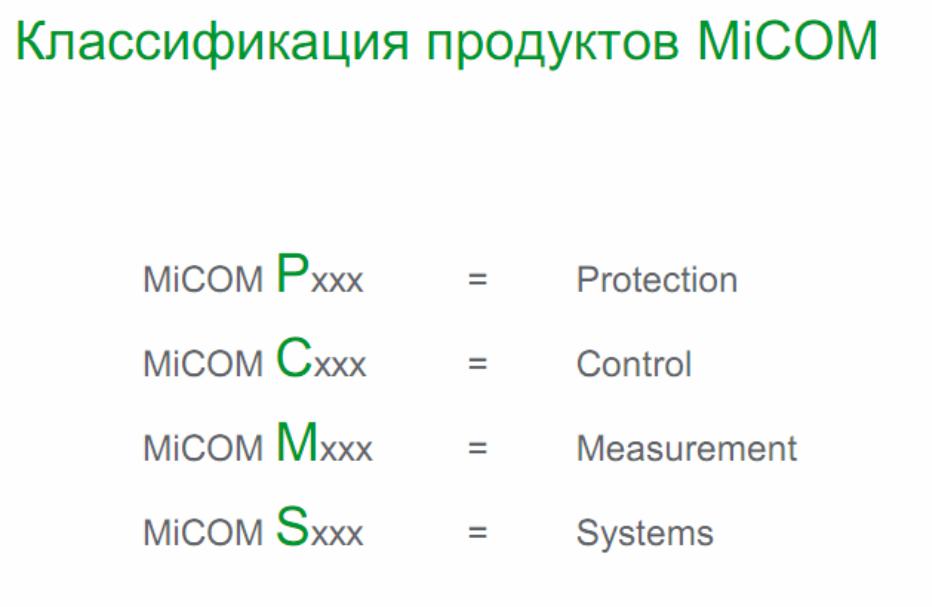
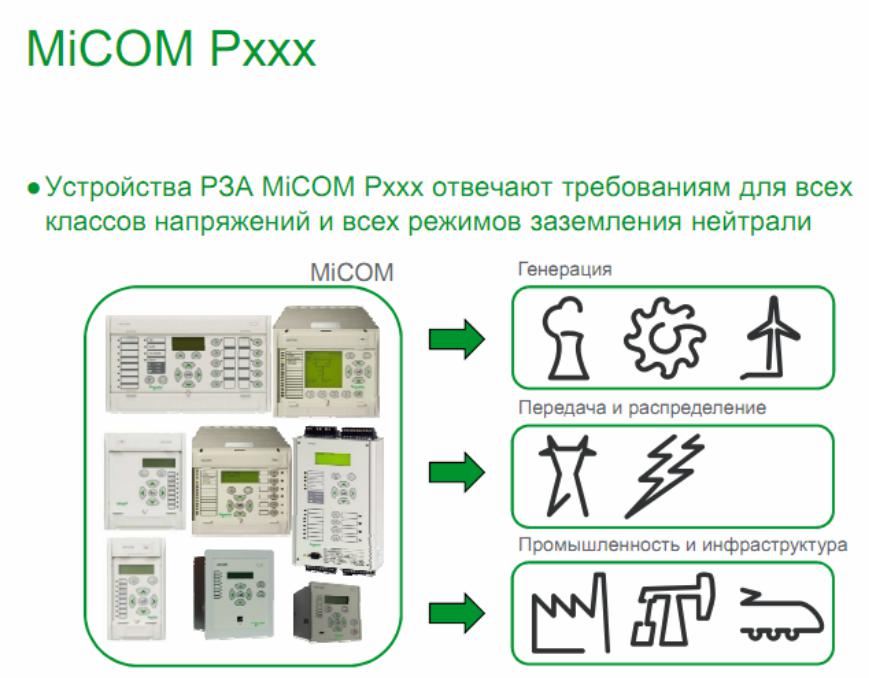
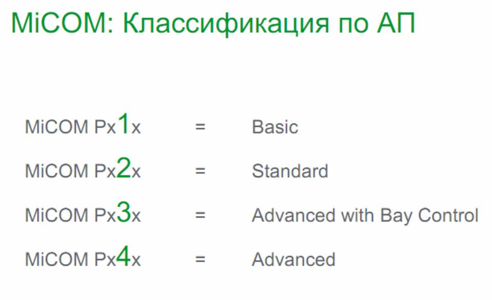
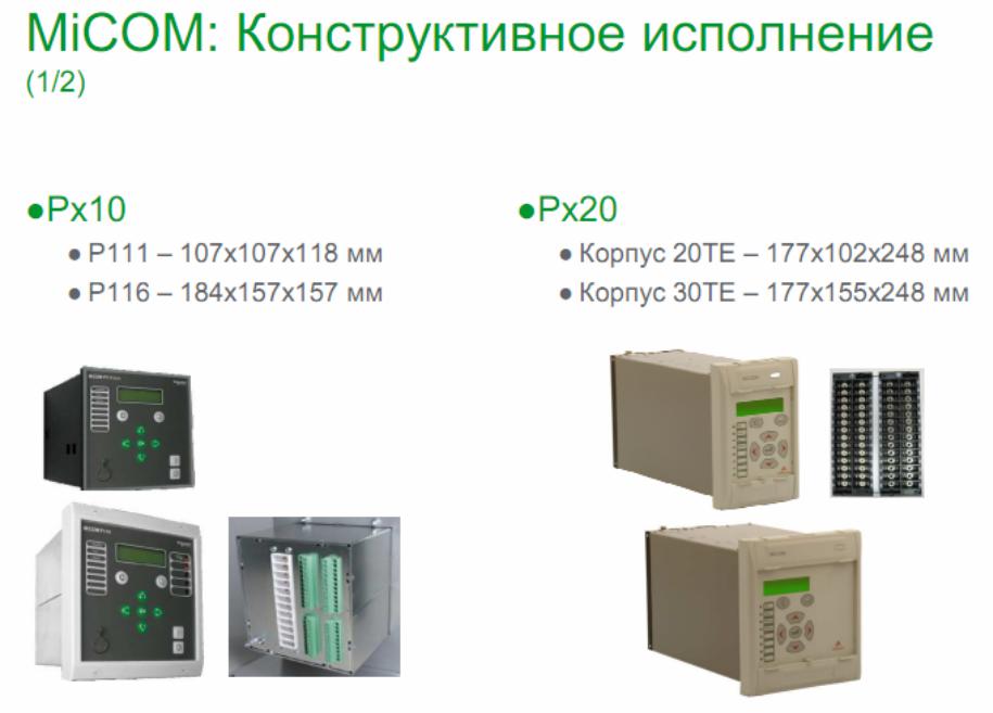
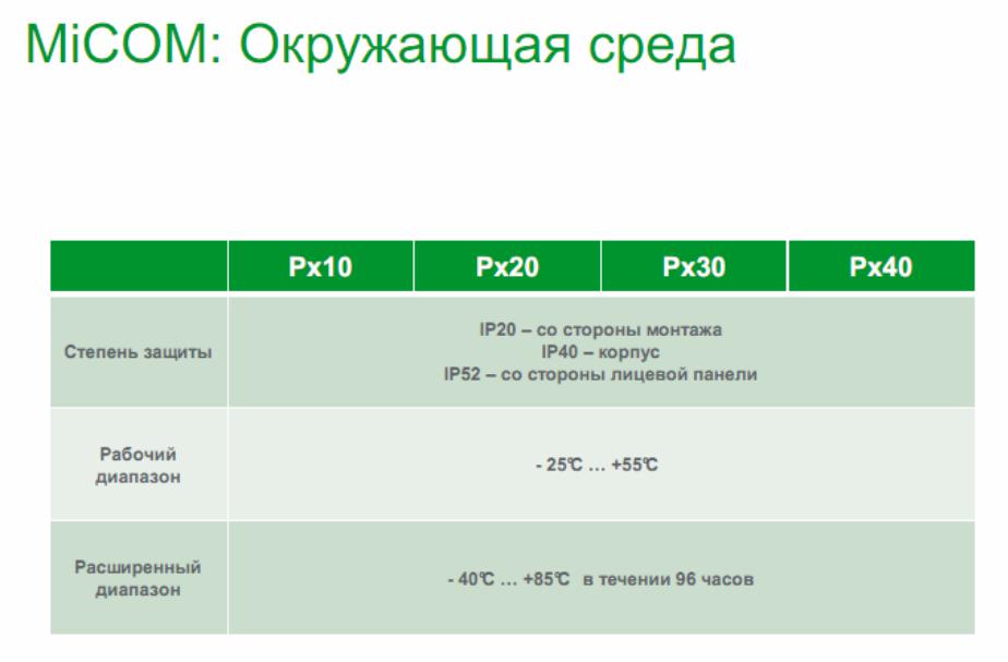
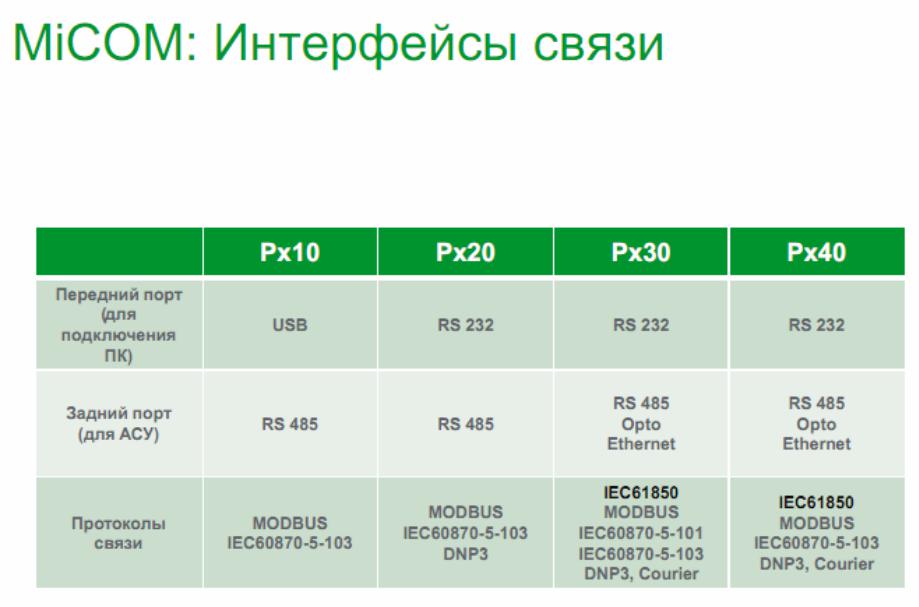
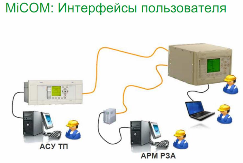
Соседние файлы в предмете [НЕСОРТИРОВАННОЕ]
- #
- #
- #
- #
- #
- #
- #
- #
- #
- #
- #
- Engineering & Technology
- Electrical Engineering
Thank you for your participation!

No more boring flashcards learning!
Learn languages, math, history, economics, chemistry and more with free Studylib Extension!
- Distribute all flashcards reviewing into small sessions
- Get inspired with a daily photo
- Import sets from Anki, Quizlet, etc
- Add Active Recall to your learning and get higher grades!
Related documents

Add this document to collection(s)
You can add this document to your study collection(s)
Sign in
Available only to authorized users
Add this document to saved
You can add this document to your saved list
Sign in
Available only to authorized users
- Home
- Documents
- MiCOM P111 — stek35.rustek35.ru/upload/iblock/4da/MiCOM_P111_manual.pdf · 2 micom p111, модель r Универсальное трехфазное реле максимальной
MiCOM P111 Универсальное реле максимальной токовой защиты Руководство пользователя Версия: 7В
Author: vunhu
Post on 06-Mar-2018
312 views
- Download
Embed Size (px)
TRANSCRIPT
-
MiCOM P111
: 7
-
2
MiCOM P111, R
:
1. . P111 R :
();
, , . P111 R . . , , , .. 2. . 7. . , . , , , . 3. : «K» «L» (
() ), «R+» — «R-» ( ) , . . , , , ( Io RS485 B, C, E R .). : ,
.4 2. 2.5 2 4 2. — , , (. ). — , (), 3IN. : — , . 4. » «: (L1):
1-2; B (L2):3-4; (L3):5-6. Vx 1-2. , «+» (L) 1, «-» (N) 2. : 13-14
( 1); 23-24 ( 2); 33-34 ( 3); 41-42-44 ( 4). 11. S1-S2 1-2 , , ( ).
1-2 1 6 PTC-, . PTC , . -
4
: S1-S2, T1-T2, . V1-C, V2-C, V3, V4 . Vx, , P111. -L , , ( )
Holmgreen. , Io> Io>> , , «» «L» «k» «l» . 1 A, , Ion=1 A.
, , Ion=5 A. Holmgreen, 5 , 111 IoN=5 . «TR+» «TR-» RS485. : ,
«TR+» «TR-» . 5.: — , , — . (. 1, 1), (. 1, 2). . 5 . , , .
, . 5.1
() ;
() ;
( ) ( );
/ ;
: «» «», , , 3- . 5.2 ;
) Vx 1-2. : l>>, l>, lp>, lo>, AUX 1, AUX2, , L1,
L1.Vx (. , ) , , . , , , , ( ).
-
5
, . Vx , ( ), : 1 (: 13-14) ,
. — «circuit breaker» () (1 0 ): 1 ; — «protection-contactor» (
) (1 1 ): 1 ; — «Bay terminal-contactor» ( RS485 ) (1 2 ): 1 .2 3 ( ) 4 ( : 41-42-44) , : — » » (4 0 ): 4 (41-42 , 41-44 ), —
» » (4 1 ): 4 (41-42 , 41-44 ), — » » (4 2 ): 4 (41-44 , 41-42 ) —
«» (4 3 ): 4 (41-44 , 41-42 ), : Vx , — ( 10). b) -. «-«. , —. — ( ),
.
«L».
, . , , » » (. 7.7: ). c) . 5 ( ) , , .
d) .
. ,
. , . e) , ,
, ,
, , , . ! , , — .
-
6
6. 6.1
, . 1 ( 13-14). : «circuit-breaker» (), «protection-contactor» (
) «Bay terminal-contactor» ( RS485 ) ( V1 RS485). a)
«circuit-breaker» ()(1 0 ): 1 , , RS485, 1
(tt): []. 2, 111, 2
(2 2 ) :
V1-C, (V1 0
) ,
RS485
, 2 ( 23-24)
: [].
, , , , . : , 2 (2 0 ). , . b) «protection-contactor» ( ) (1
1) , RS485. . Vx . . , , , . 1 , . :
S1-S2 (
» «:
0 ) RS485.
, 1 , .
-
7
) «Bay terminal-contactor» ( RS485 )
(1 2 ) , RS485 / . , V1-C : «local CB close» ( ) (V1 0
), V2-C «CB/contactor state» ( )
(V2 0 ). , 1 (13-14) ( ), , «contactor». (1) :
V1-C;
RS485.
, , , , , . , (13-14) 1 150 . , — V2-C. ( V2-C ), . : 1, ( , ).
:( «»).
, . V2-C , . , 1 ;
, RS485, 1 (13-14);
— , .
6.2. 111
:
— . ON-LINE (-, ) . OFF-LINE (-, ) , .
: 0 1. : Ip, I, I, Io, Io, AUX1, AUX2, : ( ) ( Ar), ( LdSd). , .
. : ( SEt1) / ( Set2) 0 1. -
8
, .
— , , (). 1 9998 . , : 200 /5 , , 40. , . «rEc»(«rEc1», «rEc2»,
«rEc3», «rEc4») . : , ., , ( Holmgreen). 1 9998 1. , : 75 /1 , , , , 75. , . : , .
— ( 1 0). : (0.1 9.9) 0.1 .
— ( 2 3). : (0.1 9.9) 0.1 .
. RS 485 32- 111 . , , , , . 1 254.
.. , RS485. (1,2 9,6) /.
Modbus. () S1, «0» ( , 122, 123, 126, 127, ..).
. 6.3
1. . 0 «circuit-breaker» (). 1,
-
9
. s. . 1 «protection-contactor» ( ) . RS485. Vx, 1 . — 1 ,
S1-S2. 1 RS485. 2 «bay terminal-contactor» ( RS485 ) Vx 1. , , ,
RS485 , 1 , RS485 , ( ).2. 0 «trigger of any protection on trip» ( , ) — 2 , ( AUX1
AUX2), . 1 «trip of any protection» ( ) — 2 ( AUX1 AUX2), 1. 2
«alarm of any protection» ( ) — 2 , . 3 «remote or local CB close»
( ) — 2 «». RS485 ,2 , . : 2 «3», , 2 , . , «protection-contactor» ( ) , 2 ,
«3».2 0 «without» («»)- ( , ). 1 — «latching» () — , S1-S2, T1-T2
RS485.3. 0 «trigger of any protection on trip» ( , ) — , (I, I, Ip,
Io, Io) ( AUX1 AUX2), ; 1 «trip of any protection» ( ) — 3 (I, I,
Ip, Io, Io, AUX1 AUX2), ; 2 — «alarm of any protection» ( ) , (Ip /
Io). 3 «tIo time elapsed» ( tIo ) — 3 , Io, (On 1) (On 2). 4 «start
I>» ( I>) — 3 I, (On 1) (On 2). -
10
3. 0 «without» («»)- ( , ). 1 — «latching» () — , S1-S2, T1-T2
RS485.— 4* 0 — «trigger of any protection on trip» ( , ) , , ( AUX1
AUX2). (4 , I, I, Ip, Io, Io, ); 1 «trip of any protection» ( ) — 4
( AUX1 AUX2), 1; 2 «no alarm of any protection and watchdog» ( ) —
, . 4 Vx 1 2 (41-44 , 41-42 ). , — , (Ip / Io) ; , — , , 4 (41-44 ,
41-42 ). — , 4 , , . 3 «watchdog» () — , . 4Vx 1 2 (41-44 , 41-42 ). 4 «tI>> time elapsed» (
tI>> ) — 4 , I, (On 1) (On 2). 5 «no trip of any protection
and watchdog» ( ) — , . 4 Vx 1 2 (41-44 , 41-42 ). , — , (Ip / Io)
; , — , , 4 (41-44 , 41-42 ). — , 4 , , ;S (S1-S2). , , , S1-S2 . S1-S2 . 0 «reset of LEDs and latching»
( ) — ( . : ); 1 «AUX2» — AUX2 ( : , ). : ; 2 «blocking of any
remote control» ( RS485) — RS485. : . 3 «switch setting group» ( )
— -
11
: «0» (S1-S2 ) 0; «1» (S1-S2 ) 1; 4 , ( / 2 ). . (
: ) 2 . 5 ( ). 6 «free» ( . , — RS485).
«» 1-2. , 1-2 . 1-2 : 0 — «AUX1 low state» (AUX1 ) — AUX1 ( : ,
). : ; 1 — «reset of LEDs and latching» ( ) — ( ). : ; 2 «AUX2» —
AUX2 ( : , ). : ; 3 «blocking of any remote control» ( RS485) —
RS485. : . 4 «switch setting group» ( ) — : «0» (1-2 ) 0; «1» (1-2
) 1; 5 ( ); 6 «local CB close» ( ) — ( 01). : ; 7 «AUX1» AUX1 ( : , ). : ;
V1-C. V1-C. : 0 — «local CB close» ( ) — ( 0 1). : ; 1 «AUX2» —
AUX2 ( : , ). : ; 2 — «output in maintenance» ( ) — 1, 2, 3, 4 , .
8; 3 «free» ( . , — RS485); 4 , (/ 2 ). . ( :: ) 2 ( :
);
V2-C. V2-C. : 0 «CB/contactor state» ( ) — . «» (
-
12
). , RS485, . 1 «AUX2» — AUX2 ( : , ). : ; 2 «switch setting
group» ( ) — : «0» ( ) 0; «1» ( ) 1; 3 «free» ( . , — RS485); 4
«AUX1 low state» — AUX1 ( : , ). : ; 5 , ( / 2 ). .( :
) 2 ( :
);
V3-C. V3-C. : 0 «CB/contactor closed» — . «» . , V4-C ( ). ,
RS485, ; 1 «AUX2» — AUX2 ( : ,). : ; 2 «AUX1» — AUX1 ( : , ). : ; 3 «AUX1 low state» — AUX1 (
: , ). : ; 4 «blocking logic of Ip>» ( Ip) Ip. : ; 5 ( ); 6
«blocking logic of I>>» ( I>>) I>>. : ;V4-C. V4-C. : 0 «CB/contactor opened» — . «» . , V3-C ( ). ,
RS485, ; 1 «AUX2» — AUX2 ( : , ). : ; 2 «AUX1» — AUX1 ( : , ). : ;
3 «AUX1 low state» — AUX1 ( : -
13
, ). : ; 4 «blocking logic of Ip>» ( Ip) Ip. : ; 5 ( ); 6
«blocking logic of I>>» ( I>>) I>>. : .AUX1. 0 7- ; 1 7- Io, Io Io. 6.4
. (, A, B, C, E F) — .
, .
( R) .
— — . 6.5 6.5.1 I
. (L1), (L2), (L3).
I — : 0 «DT» (); 1 «IDMT IEC SI» (); 2 «IDMT IEC VI» ; 3 «IDMT
IEC EI» .— I, .
I, 0.02 99.90 , 0.01 , TMS- IDMT, 0.02 1.5, 0.01.
I>: 0 «disable» — ; 1 «trip» — ; 2 «alarm signal» — ;
0 «disable» — I> ; 1 «enable» — I> ;
, . tI 0.02 99.90 , 0.01 .
— , tI 0.02 99.90 , 0.01 . 6.5.2 I
.
-
14
(L1), (L2), (L3).
— I>>, .
I>>, 0.02 99.90 , 0.01 .
I>>: 0 «disable» — ; 1 «trip» — ; 2 «alarm signal» — ;
0 «disable» — I>> ; 1 «enable» — I>> ; 6.5.3
Ip> . (L1), (L2), (L3).
Ip> — : 0 «DT» (); 1 «IDMT IEC SI» (); 2 «IDMT IEC VI» ; 3
«IDMT IEC EI» .— Ip>, .
Ip>, I>.
I>: 0 «disable» — ; 1 — «trip» — ; 2 «alarm signal» — ;
0 «disable» — I> ; 1 «enable» — I> ; 6.5.4 Io>
I> — : 0 «DT» (); 1 «IDMT IEC SI» (); 2 «IDMT IEC VI» ; 3
«IDMT IEC EI» .— I>, .
Io>, 0.02 99.90 , 0.01 , TMS- IDMT, 0.02 1.5, 0.01.
Io>: 0 «disable» — ; 1 — «trip» — ; 2 «alarm signal» — ;
0 «disable» — Io> ; 1 «enable» — Io> ; 6.5.5
Io>>I>> — : 0 «DT» ();
-
15
1 «IDMT IEC SI» (); 2 «IDMT IEC VI» ; 3 «IDMT IEC EI» .
— Io , .
Io>>, 0.02 99.90 , 0.01 , TMS- IDMT, 0.02 1.5, 0.01.
Io>>: 0 «disable» — ; 1 — «trip» — ; 2 «alarm signal» —
;— I>>: 0 «disable» — Io>> ; 1 «enable» — Io>>
;6.5.6 AUX1
AUX1, 0.02 99.90 , 0.01 .
AUX1: 0 «disable» — ; 1 — «trip» — ; 2 «alarm / load shedding» —
( LdSd).AUX2 :
0 «disable» , AUX1 ; 1 «A/R» () — AUX1 ; 2 «L/S Trip/Close» (
/). AUX1 () ( 1 , 0 , ); 3 — «L/S Trip» ( ). AUX1 () ( 1 , 0 ).6.5.7 AUX2
AUX2, 0.02 99.90 , 0.01 .
AUX2: 0 «disable» — ; 1 — «trip» — ; 2 «alarm / load shedding» —
( LdSd).AUX2 : 0 «disable» , AUX1 ; 1 «A/R» () — AUX1 ; 2 «L/S
Trip/Close» ( /). AUX1 () ( 1 , 0 , ); 3 — «L/S Trip» ( ). AUX1 ()
( -
16
1 , 0 ). 6.5.8
, 0.50 99.90 , 0.01 .
( ), 0.50 99.90 , 0.01 .
— , 0.02 99.90 , 0.01 .
: 0 «disable» () — ; 1 «enable 1 shot» — . 2 «enable 2 shot» —
.6.5.9
, 0.02 99.90 , 0.01 .
0 «disable» () — ; 1 «enable» () — . 6.6 . 5, . , . :
6.6.1 ( ) o (0.530) 11173914
I>> (0.530) , 0.1 4.0 I> (0.530) , 0.1 1.2 Ip>
(0.530) , 0.1 1.1 o (2.5150) 11173915I>> (2.5150) , 0.1 20.0 I> (2.5150) , 0.1 6.0 Ip>
(2.5150) , 0.1 5.5 6.6.2 o (0.011.0) 11173910Io> (0.011.0) , 0.01 0.02 Io>> (0.011.00) , 0.01 0.1 o
(0.110) 11173914Io> (0.110) , 0.01 0.4 Io>> (0.0110) , 0.01 1.0 o
(0.540) 11173915Io> (0.540) , 0.01 2.0 Io>> (0.540) , 0.01 5.0 6.7 :
o, .
-
17
, .
o , . : [email protected], +48 74 8548481.
o «000», .
o «000». 6.7.1 ( «000») — (. 6.2 b).
o
.
o , .
o , .
— (. 6.2 ). . 6.7.2
o
,
. o .
— (. 6.2 b).
o .
o — (. 6.2 ).
6.7.3
-,
.
.
. , . 7 111 : I>>, I>, Ip>, Io, AUX1, AUX2, L1, L2,
L3, [kA], [s], . , , , , . , , , . I>, I>>, Ip>,
Io:( Io Io>, Io>>).
( )
AUX1:
AUX1.
-
18
AUX1 ( ).
AUX2:
AUX2.
AUX2 ( ).
A(L1), B(L2), C(L3):
, , , .
[]
, []. , [].
[s]
, .
: I>, I>>, Ip>, Io>, AUX1, AUX2 , -. , , . 8
:, , ,
. 4 , , .
— .
— : «0» ( : 0)
«1» ( ) «2» ( )
— L1 (A) .
— L2 () .
— L3 () .
— . 9 : Vx (. , ) , , . , , , , ( ), :
1 , «protection-contactor» ( );
2/3 , .
I>>, I>, Ip>, Io>, AUX1, AUX2 , , , , , .
-
19
: , , . , . , , , :
S1-S2 , («S» «SIn» «0»);
T1-T2 , («T» «tIn» «1»);
;
,
.
.
RS485, MODBUS RTU .
-
20
-
21
-
22
10.
10.1 () , 111, . , . («General Trip» ) («General Alarm» ) ( «On»
() ). , «General Trip» ( ), «General Alarm» ( ), «General Start» (
) , . (Ip> I>) , (IDMT=), (DT=). (I>>) . ; , , . , . ,
, , . . , , : IEC-1MTt
= ,
t = =
II
M =
I = = I = = IEC 0.14 0.02 IEC 13.5 1 IEC 80 2 () IEC (). . ,
-
23
. , /. . 5.
10.2 , ( ), . ( ). 6. . 6.
-
24
10.3 111 , :
— . (2 «0»
, / 3 «0» , / 4
«0» .
— I>> (3 «4» / 4
«6» ). Ip> / I>> ( ):
— Ip>: V3 «4» / V4
«4» .
— I>>: >: V3 «6» / V4
«6» . . 7. tIp>
-
25
. 8. tI>>
10.4 AUX1 AUX2 ( ) AUX1 AUX2 : — ( : «On 1» «Ar 0») — ( : «On 2»
«Ar 0») — ( : «On 1» «Ar 1») — ( / : «On 2» «Ar 2») — ( : «On 2»
«Ar 3») AUX1 9, AUX2 10. : «tIn» ( 1-2) «SIn» ( S1-S2) , . , .: 1-2 S1-S2 . , T1-T2 S1-S2, 111.
: «V1», «V2», «V3», «V4» .
-
26
. 9. AUX1 . 10. AUX2
-
27
10.5
111R , . : —
(/ ). 11).
— ( ). 12).
AUX1 / AUX2 (. 9 10). «L/S Trip/Close» «L/S Trip». , , 111R . ,
. 1 2 . ( SIn S1-S2 tIn T1-T2) ( V1, V2, V3 V4) (. 9 10). . 11.
/ -
28
. 12.
10.6 () 10.7
111R . «Ip>», «I>», «I>>», «Io>»,
«Io>>», «AUX1», «AUX2» ( ). . ;
(«0» ; «1» ; «2» ). , ( ). , ( ). , , , , . «I>» (
)
-
29
( ). ( ) . ( «AUX1» / «AUX2»), ,
. 1 ( ),
2 ( ), , . . , (
). , . , , , , . , : 1 2 . . 52 ( V2 V4 «0»), 111 , 1 . 52 ( V3
«0»), 111 , 2 ( ). ( ;«tIn» , «V3» «V4» 5). .
-
30
. 13.
-
31
10.8 10.8.1
: —
—
. / , 14. «tIn» ( 1-2) RS485. V1 ( V1-C) (. ) 111 ( ). 111, ( )
PTC ( «3») ( ). . 14. : , . , . 52 . — , V2 «0». ( ) . , ( V1 «0»),
(2 «3») ( ). . -
32
, , ( , , , , 111 ).
10.8.2 111 :
— : «Gr 0» ( ),
— : «Gr 1» ( ).
«Gr» ( ) «SEt1»
( ). «0» , . «1» , . , , RS485 ( ). . (. » ; «). ,
«SEt2» ( ): — «Sin» ( S1-S2) «3»: » «
( ). S1-S2 , (1), (0);
— «tIn» ( 1-2) «4»: » «
( ). 1-2 , (1), (0);
— V2 ( V2-C), «2»: » «
( ). V2-C , (1), (0) .
(: [] «SEt1» ( )). .
(: «SEt1» ( ) «SEt2» ( )) .
-
33
10.8.3 , . 2, 3, 4 ):
— 2: «2» ( ) «SEt2» ( ),
— 3: «3» ( ) «SEt2» ( ),
— 4: «4» ( ) «SEt2» ( ), :
— «Clr» — ,
SEt2 ( ): «Sin» ( S1-S2) «0»: «
» ( ). : S1-S2 .
«tIn» ( 1-2) «1»: «
» ( ). : 1-2 .
— RS485 ( Modbus).
10.8.4 RS485 .
«SEt2» ( ): «Sin» ( S1-S2) «2»: «
» ( ). : S1-S2 .
«tIn» ( 1-2) «3»: » «
( ). : 1-2. . : , . , .
-
34
10.8.5 ( E, F) » «. V1 ( V1-C):
«0» » » ( )»SEt2″ ( ). V1-C 1, 2, 3, 4 ( , Vx 1-2) (. . 15). .
15. : -
35
10.8.6 10.8.6.1 1
1 . 16. . 16. 1 1 :
«Circuit Breaker» () «Contactor Protection function only» (
) «Contactor Terminal for System» ( RS485 )
10.8.6.2 «Circuit Breaker» ()
1 «0» ( ) . 1 «circuit breaker», , , RS485, 1 . 2, , 111, 2
«remote or local CB close» ( ). -
36
(2 «3» ). :
V1-C, «remote or local CB close» ( ) (V1 «0»
). ,
RS485. , 2 ( 23-24) . , , . . : «circuit breaker» 2
(2 «0» ). , .
10.8.6.3 Contactor Protection function only» ( )
(1 «1» ). , RS485. . Vx 1 . . , , 1, , , . 1 , . :
«SIn» ( S1-S2) ( » «: «0»
). «tIn» ( 1-2) (
» «:
«1» ). RS485.
, , 1 , .
-
37
10.8.6.3 «Contactor Terminal for System» ( RS485 )
(1 «2» ). , RS485 / . , V1-C : «local CB close» ( )
(V1 «0» ), V2-C «CB/contacor mode» ( «»), (V2 «0»
). Vx 1 (13-14) ( ), , «». (1) :
V1-C; RS485.
, , , . , 1 (13-14) 150 . , — V2-C ( 1 ) V3-C V4-C ( 2 ). , 1 .
: 1, ( , ). :( «»). , . ( ) , (-) . , 1;
, RS485, 1 (13-14) ;
, .
-
38
10.8.7 2, 3, 4
: 2, 3, 4 , 17. . 17. 2, 3, 4 «2», «3», «4» . , , «6.3 «.
-
39
11 11.1 : : 10250 In:
73914: 15 ( 1 ) 73915: 15 ( 5 )
: — : 3In (15 ) — : 73914: 100 73915: 250
— 0.15 : 73914: 250 73915: 1250
: : 4070 In:
73914: 15 ( 1 ) 73915: 15 ( 5 )
: — : 3In (15 ) 73914: 100 73915: 250
— 0.15 : 73914: 250 73915: 1250
11.2 : — I>, Ip>, Io>, Io>>: — I>>: EN
60255-3: — — — :— I>, I>, I>>: 73914:
— : 0.530 , 0.1 — : 0.530 , 0.1 (, I>> , , : 0.530 )
73915: — : 2.5150 , 0.1 — : 2.515 , 0.1 (, I>> , , :
2.5150 )— Io>, I>>:
73914: — : 0.110 , 0.01 — : 0.11 , 0.01 (, Io>> , , :
0.110 )73915: — : 0.540 , 0.01 — : 0.54 , 0.01 (, Io>> , , :
0.540 ): Ip>, I>, I>>, Io>, Io>>, AUX1 ( ), AUX2 (
) ( ):— : 0.0299.90 , 0.01 — ( TMS):
0.029.90, 0.01 ( I>>)
: : — Ip>, I>: 5% — I>>, Io>, Io>>: 10% : —
: 2% — : 10% , 70, I=2xI, I .
11.3 (3 , 1 ). :
— , : 5 — :
— 5 (220 ., cos=0.4) — 0.1 (220 ., L/R=40 )
: 107 : 105
11.4 6 : S1-S2, 1-2
. V1-C, V2-C, V3-C, V4-C
— : (0.81.1)Vx, Vx . — : 0.6 230 AC/DC
0.5 48 AC/DC
-
40
11.5 — 4- — — 5 — 6 — : MiCOM S1
S&R Modbus 2.10.007
11.6 Vx
(): — (2448) AC/DC — (60240) AC/DC
: (0.81.1)Vx : 4.5
: — 230 . : 2.2 — 230 . : 1 — 110 . : 0.6 — 110 . : 0.2 — 24 . :
0.03 — 24 . : 0.0211.7 RS485, (2 , «+», «-«) Modbus RTU (1200-19200)
11.8 ~0.5
11.9 : 35 DIN-
: 2 : — 4 2, — 2.5 2,
11.10 : IP 40
— : IP20 — : IP54
: — (-20+60) — (-25+70)
: 95% 40.
: EC 89/336/EEC EC 89/336/EEC : EN60255-6 (): : EN 55011, :
IEC255-0035, . EN 61000-4-2, 3 EN 61000-4-3, 2 EN 50204 3 EN
61000-4-4, 3 EN 61000-4-5, 3 1 IEC 255-22-1, 3 EN 61000-4-11 , EN
61000-4-6, 3 : 2 , 50 , 60 : 1 , 50 , 60 : >100 ( ): 5 : IEC
255-21-1, 1 : — 10 60 , 0.035 — 60 150 , 0.5 g : — 10 150 , 1 g , :
IEC 255-21-2, 1 5 g / 15 g -
42
14
. 19.
-
02/2013
220006, . , 15, 9.: (37517) 327 60 34, 327 60 72
050009, , 151/115- , 12.: (727) 397 04 00: (727) 397 04 05
010000, . , 31, 216.: (7172) 58 05 01 : (7172) 58 05 02
400089, . , 15, 12.: (8442) 93 08 41
394026, , 65, 227 .: (4732) 39 06 00./: (4732) 39 06 01
620014, . , 28, 11.: (343) 378 47 36, 378 47 37
664047, . 1 , 3 , 312./: (3952) 29 00 07, 29 20 43
420107, . , 6, 7 ./: (843) 526 55 84 / 85 / 86 / 87 / 88
236040, ., 15.: (4012) 53 59 53: (4012) 57 60 79
350063, . , 62 /. , 13, 224./: (861) 214 97 35, 214 97 36
660021, . , 3 , 302.: (3912) 56 80 95: (3912) 56 80 96
127018, . , 12, . 1- .: (495) 777 99 90: (495) 777 99 92
183038, . , . 5/23 , 421.: (8152) 28 86 90: (8152) 28 87 30
603000, . , 10 , 8./: (831) 278 97 25, 278 97 26
630132, . , 35 , 1309./: (383) 227 62 53, 227 62 54
614010, , 98 11./: (342) 281 35 15, 281 34 13, 281 36 11
344002, . , 74 1402.: (863) 261 83 22: (863) 261 83 23
443045, . , 150 .: (846) 278 40 86 : (846) 278 40 87
196158, , 40, . 4, — .: (812) 332 03 53: (812) 332 03 52
354008, . , 20 , 54.: (8622) 96 06 01, 96 06 02 : (8622) 96 06
02450098, , 132/3 ( ) 3, 9.: (347) 279 98 29: (347) 279 98 30
680000, . , 23, 4.: (4212) 30 64 70: (4212) 30 46 66
49000, . , 17, 4.: (056) 79 00 888: (056) 79 00 999
83003, . , 26.: (062) 206 50 44 : (062) 206 50 45
03057, . , 20, .: (044) 538 14 70: (044) 538 14 71
79015, . , 72, . 1./: (032) 298 85 85
54030, . , 25 5 .: (0512) 58 24 67: (0512) 58 24 68
.: (050) 446 50 90, 383 41 75
61070, . , 1 Telesens 204 .: (057) 719 07 49 : (057) 719 07
79Schneider Electric
.: 8 (800) 200 64 46 () .: (495) 777 99 88, : (495) 777 99 94
[email protected] www.schneiderelectric.com— .
www.MyEnergyUniversity.com