Материал из BikesWiki — энциклопедия японских мотоциклов
Перейти к: навигация, поиск

Ниже представлены прямые ссылки на скачку сервисной документации.
Для Kawasaki KX250F
- Kawasaki KX250F: Сервисный Мануал (Service Manual), 2004-2005, KX250-N
- Kawasaki KX250F: Сервисный Мануал (Service Manual), 2006-2008, KX250-T
- Kawasaki KX250F: Сервисный Мануал (Service Manual), 2010, KX250-X
- Kawasaki KX250F: Сервисный Мануал (Service Manual), 2011-2012, KX250-Y
- Kawasaki KX250F: Сервисный Мануал (Service Manual), 2013-2016, KX250-Z
Обзор модели
- Kawasaki KX250F
Не можете найти ответ на свой вопрос в руководстве? Вы можете найти ответ на свой вопрос ниже, в разделе часто задаваемых вопросов о Kawasaki KX250F (2013).
Как перевести мили в километры?
В чем разница между топливом E10 и E5?
Какова рекомендуемая частота замены масляного фильтра в двигателе Kawasaki?
Как часто следует менять масло в двигателе Kawasaki?
Как удалить ржавчину с устройства Kawasaki Мотоцикл?
Инструкция Kawasaki KX250F (2013) доступно в русский?
Не нашли свой вопрос? Задайте свой вопрос здесь


Item # 99987-1770
MSRP
$22.95
Kawasaki Owner’s Manuals include Important Safety Information, Operating Instructions, and Maintenance and Storage Information.
Most items ship to dealer within 5-7 business days for free. Special dealer only items may be excluded.
Additional shipping charges apply to qualified ship to home orders.
Price and specifications are subject to change without notice or liability. Availability is subject to production, stocking and demand. Manufacturers suggested retail prices shown.
 WARNING: Cancer and reproductive harm www.P65Warnings.ca.gov
- WARRANTY INFORMATION
Kawasaki KX250F -: Available Instructions
Note for Owners:
Guidesimo.com webproject is not a service center of Kawasaki trademark and does not carries out works for diagnosis and repair of faulty Kawasaki KX250F — equipment. For quality services, please contact an official service center of Kawasaki company. On our website you can read and download documentation for your Kawasaki KX250F — device for free and familiarize yourself with the technical specifications of device.
-
Honda GB500 Twin
HAYNES SERVICE & REPAIR MANUAL CB5DD TWin ’93 to ’01 «Haynes Manuals just cannot be beaten» Molor Cycle News ——————— — ——• Performance data. Model history. Wiring diagrams • Tools and workshop lips IN FULL COLOUR …
GB500 Twin Motorcycle, 250
-
Triumph Daytona 675
1ForewordFOREWORDThis handbook contains information on the Triumph Daytona 675, Daytona 675 R, Street Tripleand Street Triple R motorcycles. Always store this owner’s handbook with the motorcycle andrefer to it for information whenever necessary.Warnings, Cautions and NotesThroughout this owner’s handbookparticularly important information ispresented in the following form:Note:• This n …
Daytona 675 Motorcycle, 158
-
Honda 20010 VT1300CX
20010 VT1300CXSET-UP INSTRUCTIONSSet-up and pre-delivery servicemust be performed by an authorizedHonda motorcycle dealer.©2009 American Honda Motor Co., Inc. – All Rights ReservedMPD 12779 (0903) Issued: March 2009 …
20010 VT1300CX Motorcycle, 18
-
Mocka Rocket Bikes
spannerx1ALL nuts and bolts must be checked and tightened before first use. Regularly check all screws are tight to ensure safety. Mocka Rocket Bikes are designed for children aged 18 months — 4 years. These bikes should not be used on public roads or near traffic. Wearing a helmet is advisable. Only one child at a time should use the bike. Recommended for children under 30kgs.Adult super …
Rocket Bikes Motorcycle, 4
Popular Motorcycle User Guides:
 Loading…
![]()
Quick Reference Guide
This Quick Reference Guide will assist you in finding the information you’re looking for.
|
GENERAL INFORMATION |
j |
|
MAINTENANCE AND ADJUSTMENT |
j |
|
TROUBLESHOOTING GUIDE |
j |
|
TUNING |
j |
|
STORAGE |
j |
A Table of Contents is included after the Foreword.
IMPORTANT INFORMATION
•This vehicle is designed for the operator only, no passengers.
•This vehicle is a competition model only and was not manufactured for use on public streets, roads or highways.
•The use of this vehicle should be limited to participation in sanctioned competition events upon a closed course.
•This vehicle should not be used for general off-road recreational riding.
•Read owner’s manual.
Whenever you see the symbols shown below, heed their instructions! Always follow safe operating and maintenance practices.
 DANGER
DANGER indicates a hazardous situation which, if not avoided, will result in death or serious injury.
 WARNING
WARNING indicates a hazardous situation which, if not avoided, could result in death or serious injury.
NOTICE
NOTICE is used to address practices not related to personal injury.
NOTE
○NOTE indicates information that may help or guide you in the operation or service of the vehicle.
IMPORTANT NOTICE
THIS VEHICLE IS A COMPETITION MODEL ONLY AND WAS NOT MANUFACTURED FOR, NOR SHOULD IT BE USED ON, PUBLIC STREETS, ROADS, OR HIGHWAYS. THE USE OF THIS VEHICLE SHOULD BE LIMITED TO PARTICIPATION IN SANCTIONED COMPETITION EVENTS UPON A CLOSED COURSE. THIS VEHICLE SHOULD NOT BE USED FOR GENERAL OFF-ROAD RECREATIONAL RIDING. READ OWNER’S MANUAL.
 WARNING
THIS VEHICLE SHOULD NOT BE USED FOR GENERAL OFF-ROAD RECREATIONAL RIDING.
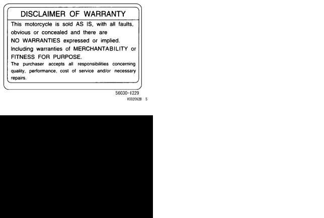
DISCLAIMER OF WARRANTY
This motorcycle is sold AS IS, with all faults, obvious or concealed and there are NO WARRANTIES, expressed or implied. Including warranties of MERCHANTABILITY or FITNESS FOR PURPOSE.
The purchaser accepts all responsibilities concerning quality, performance, cost of service and/or necessary repairs.
Motorcycle Noise Emission Control Information
This motorcycle is designed for closed course competition use only. It does not conform to U.S. EPA motorcycle noise standards.
NOTICE
Off-road motorcycling is a wonderful sport, and we hope you will enjoy it to the fullest. However, if improperly conducted, this sport has the potential to cause environmental problems as well as conflicts with other people. Responsible use of your off-road motorcycle will ensure that these problems and conflicts do not occur. TO PROTECT THE FUTURE OF YOUR SPORT, MAKE SURE YOU USE YOUR MOTORCYCLE LEGALLY, SHOW CONCERN FOR THE ENVIRONMENT, AND RESPECT THE RIGHTS OF OTHER PEOPLE.
 WARNING
The engine exhaust from this product contains chemicals known to the State of California to cause cancer, birth defects or other reproductive harm.
FOREWORD
Congratulations on your choosing this Kawasaki motorcycle. Your new motorcycle is the product of Kawasaki’s advanced engineering, exhaustive testing, and continuous striving for a superior lightweight, high-performance machine with superb handling and stability for racing and sporting use.
Your new KX is a highly tuned competition machine for participation in racing events. As with any mechanical device, proper care and maintenance are important for trouble-free operation and top performance. This manual is written to enable you to keep your KX properly tuned and adjusted.
Due to improvements in design and performance made during production, in some cases there may be minor discrepancies between the actual vehicle and the illustrations and text in this manual.
KAWASAKI HEAVY INDUSTRIES, LTD.
Motorcycle & Engine Company
|
© 2014 Kawasaki Heavy Industries, Ltd. |
Feb. 14, 2014. (1) |

TABLE OF CONTENTS
|
SPECIFICATIONS…………………………………….. |
8 |
|
GENERAL INFORMATION………………………… |
11 |
|
Location of Labels ………………………………….. |
11 |
|
Location of Parts ……………………………………. |
16 |
|
Side Stand…………………………………………….. |
19 |
|
Fuel ……………………………………………………… |
20 |
|
Fuel Requirement:……………………………….. |
21 |
|
Kick Pedal …………………………………………….. |
23 |
|
Starting the Engine…………………………………. |
23 |
|
Launch Control Mode ……………………………… |
25 |
|
DFI Setting Data Selection ………………………. |
26 |
|
Shifting Gears………………………………………… |
27 |
|
Stopping the Motorcycle………………………….. |
28 |
|
Stopping the Engine ……………………………….. |
28 |
|
Break-In………………………………………………… |
29 |
|
Daily Pre-Ride Checks ……………………………. |
30 |
|
After-Race Checks …………………………………. |
32 |
|
MAINTENANCE AND ADJUSTMENT…………. |
33 |
|
Periodic Maintenance Chart …………………….. |
33 |
|
Engine Oil……………………………………………… |
38 |
|
Cooling System ……………………………………… |
43 |
|
Spark Plug…………………………………………….. |
47 |
|
Air Cleaner ……………………………………………. |
54 |
|
Throttle Cable………………………………………… |
60 |
|
Throttle Body Assy …………………………………. |
61 |
|
Clutch …………………………………………………… |
72 |
|
Valve Clearance …………………………………….. |
79 |
|
Exhaust System …………………………………….. |
84 |
|
Rear Axle Nut ………………………………………… |
88 |
|
Drive Chain……………………………………………. |
89 |
|
Adjustable Ergonomics……………………………. |
94 |
|
Footpeg ………………………………………………… |
96 |
|
Brakes ………………………………………………….. |
98 |
|
Steering ………………………………………………… |
101 |
|
Front Suspension …………………………………… |
104 |
|
Rear Suspension (UNI-TRAK®)………………… |
154 |
|
Wheels …………………………………………………. |
160 |
|
Hoses Inspection……………………………………. |
162 |
|
Tightening Torques of Nuts and Bolts………… |
163 |
|
Cleaning Your Motorcycle………………………… |
167 |
|
Lubrication…………………………………………….. |
169 |
|
DFI Self-Diagnosis ………………………………… |
172 |
|
TROUBLESHOOTING GUIDE……………………. |
179 |
|
TUNING…………………………………………………… |
186 |
|
Suspension……………………………………………. |
186 |
|
Gearing…………………………………………………. |
192 |
|
Special Care According to Track Conditions . 193 |
|
|
OPTIONAL PARTS …………………………………… |
194 |
|
PRE-RACE CHECKS AND AFTER-RACE |
|
|
MAINTENANCE…………………………………….. |
195 |
|
STORAGE……………………………………………….. |
197 |
|
Before Storage ………………………………………. |
197 |
|
After Storage …………………………………………. |
198 |
|
ENVIRONMENTAL PROTECTION……………… |
199 |
|
WIRING DIAGRAM…………………………………… |
200 |
8 SPECIFICATIONS
SPECIFICATIONS |
||
|
DIMENSIONS |
||
|
Overall Length |
2 170 mm (85.43 in.) |
|
|
Overall Width |
820 mm (32.3 in.) |
|
|
Overall Height |
1 270 mm (50.00 in.) |
|
|
Wheelbase |
1 475 mm (58.07 in.) |
|
|
Road Clearance |
330 mm (13.0 in.) |
|
|
Curb Mass |
106.0 kg (233.7 lb) |
|
|
Fuel Tank Capacity |
6.1 L (1.6 US gal) |
|
|
ENGINE |
||
|
Type |
4-stroke, DOHC, single-cylinder, liquid-cooled |
|
|
Bore × Stroke |
77.0 × 53.6 mm (3.03 × 2.11 in.) |
|
|
Displacement |
249 cm³ (15.2 cu in.) |
|
|
Compression Ratio |
13.8:1 |
|
|
Fuel System |
FI (Fuel Injection) |
|
|
Starting System |
Primary kick |
|
|
Ignition System |
Digital DC-CDI |
|
|
Ignition Timing |
4° BTDC @2 000 r/min (rpm) |
|
|
Lubrication System |
Forced lubrication (semi-dry sump) |
|
|
Spark Plug |
NGK CPR8EB-9 |
|
|
Spark Plug Terminal |
Solid-post |
|
SPECIFICATIONS 9 |
|
|
TRANSMISSION |
|
|
Transmission Type |
5-speed, constant mesh, return shift |
|
Clutch Type |
Wet, multi disc |
|
Driving System |
Chain drive |
|
Gear Ratio: |
|
|
1st |
2.142 (30/14) |
|
2nd |
1.750 (28/16) |
|
3rd |
1.444 (26/18) |
|
4th |
1.235 (21/17) |
|
5th |
1.045 (23/22) |
|
Primary Reduction Ratio |
3.350 (67/20) |
|
Final Reduction Ratio |
3.846 (50/13) |
|
Overall Drive Ratio |
13.470 at Top gear |
|
Engine Oil: |
|
|
Type |
API SG, SH, SJ, SL or SM with JASO MA, MA1 or MA2 |
|
Viscosity |
SAE 10W-40 |
|
Capacity |
1.0 L (1.1 US qt) |
|
FRAME |
|
|
Type |
Tubular, semi-double cradle |
|
Steering Angle |
42° to either side |
|
Caster |
28.7° |
|
Trail |
126.4 mm (4.98 in.) |
|
10 SPECIFICATIONS |
|
|
Tire Size/Type: |
|
|
Front |
80/100-21 51M/DUNLOP MX51FA |
|
Rear |
100/90-19 57M/DUNLOP MX51 |
|
Rim Size: |
|
|
Front |
21 × 1.60 |
|
Rear |
19 × 1.85 |
|
Suspension: |
|
|
Front |
Telescopic fork (upside-down) |
|
Rear |
New Uni-trak® swingarm |
|
Front Suspension Travel |
315 mm (12.4 in.) |
|
Rear Wheel Travel |
310 mm (12.2 in.) |
|
Front Fork Oil: |
|
|
Type |
Kawasaki Fork Oil SS19 |
|
Amount (Left Front Fork): |
|
|
Cylinder Unit |
330 mL (11.2 US oz.) |
|
Outer Tube |
300 mL (10.1 US oz.) |
|
Amount (Right Front Fork) |
223 mL (7.54 US oz.) |
|
BRAKES |
|
|
Type: |
|
|
Front |
Single disc |
|
Rear |
Single disc |
Specifications are subject to change without notice.
GENERAL INFORMATION 11
|
j |
||||||
GENERAL INFORMATION |
||||||
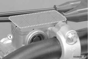
Location of Labels |
||||||
|
All warning labels which are on your vehicle are |
||||||
|
repeated here. Read labels on your vehicle and un- |
||||||
|
derstand them thoroughly. They contain information |
||||||
|
which is important for your safety and the safety of |
||||||
|
anyone else who may operate your vehicle. There- |
||||||
|
fore, it is very important that all warning labels be on |
||||||
|
your vehicle in the locations shown. If any label is |
||||||
|
missing, damaged, or worn, get a replacement from |
||||||
|
your Kawasaki dealer and install it in the correct po- |
||||||
|
sition. |
||||||
|
NOTE |
||||||
|
1. Brake Fluid (Front) |
||||||
|
○The sample warning labels in this section have |
||||||
|
part numbers to help you and your dealer obtain |
||||||
|
the correct replacement. |

12 GENERAL INFORMATION
 j
j
2. Brake Fluid (Rear)
3. Radiator Cap Danger
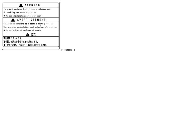
4. Rear Shock Absorber Warning
GENERAL INFORMATION 13
j
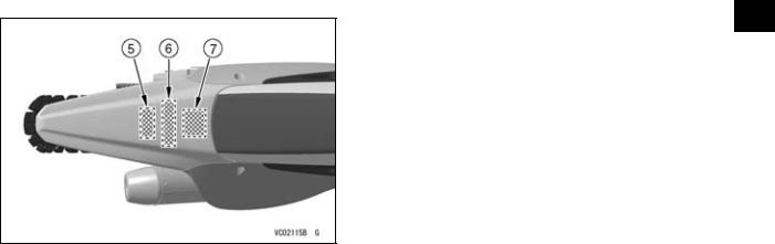
5.Noise Emission Control Information
6.Important Information
7.Disclaimer of Warranty
14 GENERAL INFORMATION
|
2) |
4) |
|
GENERAL INFORMATION 15
|
5) |
7) |
j |
||
6)
16 GENERAL INFORMATION
 j
j
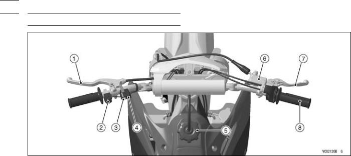
Location of Parts
|
1. |
Clutch Lever |
4. |
Orange Launch Control |
6. |
Front Brake Fluid Reservoir |
|
2. |
Engine Stop Button |
Mode/FI Warning Indicator |
7. |
Front Brake Lever |
|
|
3. |
Launch Control Mode |
Light |
8. |
Throttle Grip |
|
|
Button |
5. |
Fuel Tank Cap |
GENERAL INFORMATION 17
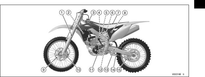
j
|
1. |
Front Fork |
6. |
Upstream Injector |
11. |
Shift Pedal |
|
2. |
Radiator |
7. |
Seat |
12. |
Rear Shock Absorber |
|
3. |
Fuel Tank |
8. |
Air Cleaner Element |
13. |
Swingarm |
|
4. |
Throttle Body Assy |
9. |
Brake Disc |
14. |
Drive Chain |
|
5. |
Downstream Injector |
10. |
Brake Caliper |
15. |
Chain Guide |
18 GENERAL INFORMATION
 j
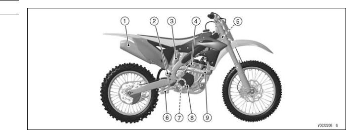
j
|
1. |
Muffler |
6. |
Uni-Trak® Tie-Rod and Rocker Arm |
|
2. |
Rear Brake Fluid Reservoir |
7. |
Oil Level Inspection Window |
|
3. |
Rear Shock Absorber Gas Reservoir |
8. |
Rear Brake Pedal |
|
4. |
Kick Pedal |
9. |
Exhaust Pipe |
|
5. |
DFI Setting Data Selection Connector |

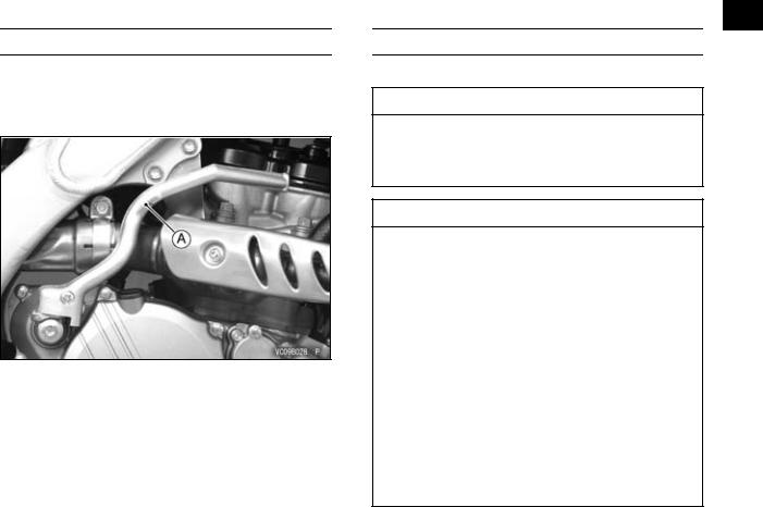
Side Stand
To install the side stand, insert its flat end into the rear axle as shown in the figure.
GENERAL INFORMATION 19
○Support the motorcycle with a suitable stand to perform maintenance or adjustment procedures.
A.Side Stand
B.Rear Axle
 WARNING
Riding with the side stand can cause a crash resulting in injury. Do not start the engine or attempt to ride the motorcycle when the side stand is installed.
![]()
20 GENERAL INFORMATION
 j
j
Fuel
This Kawasaki KX has a 4-stroke engine that requires a gasoline.
The capacity of the fuel tank is 6.1 L (1.6 US gal). To open the fuel tank cap, disconnect the breather hose from the hole in the steering stem, and turn the tank cap counterclockwise.
Avoid filling the tank in the rain or where heavy dust is blowing so that the fuel does not get contaminated.
A. Tank Cap
B. Fuel Tank
C. Top Level
D. Filler Neck
A.Fuel Tank Cap
B.Breather Hose
 WARNING
Gasoline is extremely flammable and can be explosive under certain conditions. Always stop the engine and do not smoke. Make sure the area is well-ventilated and free from any source of flame or sparks; this includes any appliance with a pilot light. Never fill the tank so the fuel level rises into the filler neck. If the tank is overfilled, heat may cause the fuel to expand and overflow through the vents in the tank cap. After refueling, make sure the fuel tank cap is closed securely. If gasoline is spilled on the fuel tank, wipe it off immediately.
Fuel Requirement:
Fuel Type
Use clean, fresh unleaded gasoline with a minimum Antiknock Index of 90. The Antiknock Index is posted on service station pumps in the U.S.A. The octane rating of a gasoline is a measure of its resistance to detonation or “knocking”. The Antiknock Index is an average of the Research Octane Number (RON) and the Motor Octane Number (MON) as shown in the table below.
|
Octane Rating Method |
Minimum |
|||
|
Rating |
||||
|
Antiknock Index |
(RON + MON) |
90 |
||
|
2 |
||||
GENERAL INFORMATION 21
|
j |
||
|
NOTICE |
||
|
If engine “knocking” or “pinging” occurs, |
||
|
use a different brand of gasoline of a higher |
||
|
octane rating. |
||
|
If this condition is allowed to continue it can |
||
|
lead to severe engine damage. |
||
|
Gasoline quality is important. Fuels of low |
||
|
quality or not meeting standard industry |
||
|
specifications may result in unsatisfactory |
||
|
performance. Operating problems that result |
||
|
from the use of poor quality or nonrecom- |
||
|
mended fuel may not be covered under your |
||
|
warranty. |
Fuels Containing Oxygenates
Gasoline frequently contains oxygenates (alcohols and ethers) especially in areas of the U.S. and Canada which are required to sell such reformulated fuels as part of a strategy to reduce exhaust emissions.
The types and volume of fuel oxygenates approved for use in unleaded gasoline by the U.S. Environmental Protection Agency include a broad range of alcohols and ethers, but only two components have seen any significant level of commercial use.
Gasoline/Alcohol Blends — Gasoline containing up to 10% ethanol (alcohol produced from agricultural products such as corn), also known as “gasohol” is approved for use.

22 GENERAL INFORMATION
|
j |
||
|
NOTICE |
||
|
Avoid using blends of unleaded gasoline and |
||
|
methanol (wood alcohol) whenever possible, |
||
|
and never use “gasohol” containing more |
||
|
than 5% methanol. Fuel system damage and |
||
|
performance problems may result. |
||
|
Gasoline/Ether Blends — The most common ether |
||
|
is methyl tertiary butyl ether (MTBE). You may use |
||
|
gasoline containing up to 15% MTBE. |
||
|
NOTE |
||
|
○Other oxygenates approved for use in unleaded |
||
|
gasoline include TAME (up to 16.7%) and ETBE |
||
|
(up to 17.2%). Fuel containing these oxygenates |
can also be used in your Kawasaki.
NOTICE
Never use gasoline with an octane rating lower than the minimum specified by Kawasaki.
Never use “gasohol” with more than 10% ethanol, or more than 5% methanol. Gasoline containing methanol must also be blended with cosolvents and corrosion inhibitors.
Certain ingredients of gasoline may cause paint fading or damage. Be extra careful not to spill gasoline or gasoline oxygenate blends during refueling.
When not operating your Kawasaki for 30 to 60 days, mix a fuel stabilizer (such as STA-BIL) with the gasoline in the fuel tank. Fuel stabilizer additives inhibit oxidation of the fuel which minimizes gummy deposits.
Never store this product with “gasohol” in the fuel system. Before storage it is recommended that you drain all fuel from the fuel system. See the Storage section in this manual.
Kick Pedal
This motorcycle is equipped with a primary kick starting system. When the clutch lever is pulled, the motorcycle can be started with the transmission in any gear.
A. Kick Pedal
GENERAL INFORMATION 23
j
Starting the Engine
• Shift the transmission into neutral.
 WARNING
Riding with the side stand can cause a crash resulting in injury. Do not start the engine or attempt to ride the motorcycle when the side stand is installed.
NOTICE
This motorcycle is designed for competition use only. Therefore, the radiator does not incorporate a coolant reserve tank or cooling fan. Prolonged idling of the engine with no airflow through the radiator can cause coolant loss and engine overheating resulting in possible engine damage. Any riding conditions that increase engine temperature will further reduce idling time before coolant loss occurs. These conditions include high ambient temperature, sandy or muddy terrain, or other conditions causing high engine loads at low speeds. Furthermore, warming the engine up excessively before operation, or leaving idling with the hot engine temperature after operation results in the engine overheating, too.
24 GENERAL INFORMATION
|
j |
When engine is cold — |
When engine is already warm or restarts — |
|
|
• Pull out the idle adjusting screw/choke knob. |
• Kick the engine over, leaving the throttle closed |
||
|
without using the idle adjusting screw/choke knob. |
|||
|
NOTE |
|||
|
○If the engine fails starting, open the throttle fully |
|||
|
and depress the kick pedal slowly about 4 5 |
|||
|
times to clear too rich fuel mixtures in the engine. |
|||
|
Then, kick the engine over, leaving the throttle |
|||
|
closed. |
|||
A.Idle Adjusting Screw/Choke Knob
•Find the kick pedal position around the top so that the resistance to depress the kick pedal is fully felt by pushing down the kick pedal slowly.
•Kick the engine over, leaving the throttle closed.
NOTE
○When the clutch lever is pulled, the motorcycle can be started with the transmission in any gear.
•Even after the engine has started, do not push back immediately the idle adjusting screw/choke knob until the engine is thoroughly warmed up.
GENERAL INFORMATION 25
|
• When shifting into 3rd, the system is deactivated |
j |
|||
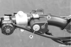
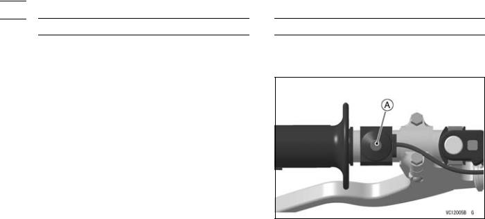
Launch Control Mode |
||||
|
automatically. |
||||
|
The launch control mode can be used to adjust ig- |
||||
|
nition timing to help riders get better starts on slip- |
||||
|
pery terrain. |
||||
|
The system’s effectiveness is dependent on rider |
||||
|
skill, technique and terrain conditions. |
||||
|
Launch Control Mode Setting |
||||
|
• The launch control mode can be set when the en- |
||||
|
gine is running and in neutral, 1st or 2nd gear. |
||||
|
When activated, it only functions in 1st and 2nd |
||||
|
gear. |
||||
|
• When pushing the launch control mode button for |
||||
|
over two seconds, the orange launch control mode |
||||
|
indicator light will blink to indicate the system is |
||||
|
operating. |
A. Launch Control Mode Button |
|||
|
B. Orange Launch Control Mode/FI Warning |
||||
|
Indicator Light |
26 GENERAL INFORMATION
 j
j
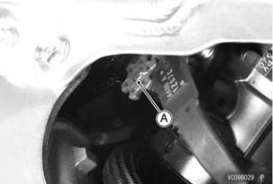
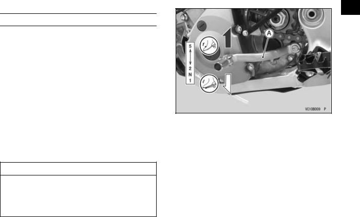
DFI Setting Data Selection
Three DFI settings are available to suit various track conditions. They are easily activated by changing the wiring connector on the side of the frame when the engine is stopped.
|
Track Condition |
Connector Color |
|
Soft |
White |
|
Standard |
Green |
|
Hard |
Black |
•Change the connector on the right front of the frame to suit the track condition with the engine stopped.
NOTE
○If the connector is changed while the engine is running, the DFI setting does not change.
○The ECU is set to the standard track condition when operated without a connector. However, always have one of the three connectors attached when riding to prevent dust and mud from accumulating in the connector harness.
○The KX FI calibration kit (Part No. 99999-0394) can be used for changing the DFI setting.
A. Connector
Shifting Gears
This motorcycle is equipped with a 5-speed “return shift” transmission. The neutral is located halfway between 1st and 2nd gear. “Return shift” means that when shifting up or down, each gear must be engaged before the next higher or lower gear may be selected.
•To engage first gear from the neutral position, pull in the clutch lever and push down on the shift pedal, gently release the clutch lever, then release the shift pedal.
•To shift up to the next gear, pull in the clutch lever, lift the shift pedal with your toes, gently release the clutch lever, and then release the shift pedal.
•To shift down to the next gear, pull in the clutch lever, push the shift pedal down as far as it will go, gently release the clutch lever, then release the shift pedal.
NOTICE
When changing gears, press firmly on the shift pedal to ensure proper shifting. Careless, incomplete shifting can cause the transmission to jump out of gear and lead to engine damage.
GENERAL INFORMATION 27
j
A. Shift Pedal
28 GENERAL INFORMATION
 j
j
Stopping the Motorcycle
For maximum deceleration, close the throttle and apply both front and rear brakes. Pull in the clutch lever as the motorcycle comes to a stop. Independent use of the front or rear brake may be advantageous in certain circumstances. Shift down progressively to ensure good engine response at all speeds.
Stopping the Engine
•Shift the transmission into the neutral position.
•Close the throttle completely and push the engine stop button.
A. Engine Stop Button
Break-In
A brief break-in procedure must be carried out to obtain the proper operating clearances in the engine and transmission, which are necessary for performance and reliability.
NOTICE
For the first hour or 20 km (12 mile) of operation, run the engine at low and moderate engine speeds. See details below.
Break in the engine as follows.
1.Start the engine and let it idle until it is thoroughly warmed up.
2.Ride the motorcycle for about 20 minutes within 1/2 throttle opening.
3.Stop and let the engine cool completely. Be sure to check the tightness of nuts and bolts, oil leakage, coolant leakage and any irregularities.
4.Start the engine and ride the motorcycle for about 40 minutes within 3/4 throttle opening.
GENERAL INFORMATION 29
j
5. Stop and let the engine cool completely. Be sure to fully check the tightness of nuts and bolts, oil leakage, and any irregularities, especially, each cable elongation, brake play, chain slack and spoke tightness.
6. Change the engine oil, oil filter and front fork/rear shock absorber oil to the new one.
7. After the break-in procedure has been properly carried out, the motorcycle is ready for regular operation. Using the proper riding skills and techniques and avoiding recklessly high engine speeds will keep the engine trouble-free.
NOTICE
When any following parts have been replaced, the same break-in procedure as the new motorcycle must be carried out for one hour or 20 km (12 mile):
Cylinder, Piston, Piston pin, Piston ring, Valve, Valve lifter, Camshaft, Crankshaft, Mission gear, etc.
![]()
30 GENERAL INFORMATION
 j
j
Daily Pre-Ride Checks
Check the following items each day before you ride. The time required is minimal, and habitual performance of these checks will help ensure a safe, reliable ride.
If any irregularities are found during these checks, refer to the appropriate section and take the action required to return the motorcycle to a safe operating condition.
 WARNING
Failure to perform these checks before operation may result in serious damage or an accident. Always perform daily checks before operation.
 DANGER
Exhaust gas contains carbon monoxide, a colorless, odorless poisonous gas. Inhaling carbon monoxide can cause serious brain injury or death. DO NOT run the engine in enclosed areas. Operate only in a well-ventilated area.
|
Engine |
|
|
Engine Oil ……………………………… |
No leakage |
|
Level correct |
|
|
Coolant …………………………………. |
No leakage |
|
Level correct (engine cold) |
|
|
Radiator Cap …………………………. |
Properly installed |
|
Spark Plug …………………………….. |
Correctly torqued |
|
Cylinder Head Cover ………………. |
Correctly torqued |
|
Clutch …………………………………… |
Functions properly |
|
Air Cleaner ……………………………. |
Clean |
|
Apply oil to air cleaner element |
|
|
Properly installed |
|
|
Muffler ………………………………….. |
No damage |

|
Properly installed |
|
|
Engine Sprocket …………………….. |
No wear or damage |
|
Frame |
|
|
Tires …………………………………….. |
Overall condition good |
|
No wear or damage |
|
|
Pressure correct |
|
|
Air valve cap installed |
|
|
Spokes …………………………………. |
No looseness |
|
Drive Chain …………………………… |
Overall condition good |
|
Chain slack correct |
|
|
Oil if necessary |
|
|
Front and Rear Brakes ……………. |
Function properly |
|
Lever and pedal play correct |
|
|
No fluid leakage |
|
|
Throttle …………………………………. |
Functions properly |
|
Throttle grip returns smoothly |
|
|
Steering ………………………………… |
Smooth but not loose from lock to lock |
|
No binding due to control cables |
|
|
Front Fork ……………………………… |
Functions properly |
|
No oil leakage |
|
|
Rear Shock Absorber ……………… |
Functions properly |
|
No oil leakage |
|
|
Fuel Tank ………………………………. |
Mounted securely |
|
No fuel leakage |
|
|
Rear Sprocket ……………………….. |
No wear or damage |
|
Engine Stop Button ………………… |
Functions properly |
|
Launch Control Mode Button …… |
Functions properly |
|
Nuts, Bolts, Fasteners …………….. |
Properly tightened |

32 GENERAL INFORMATION
 j
j
After-Race Checks
After racing, first clean the motorcycle, then inspect the entire motorcycle with special attention to the air cleaner, brakes, etc.
Carry out the general lubrication and make necessary adjustments.

MAINTENANCE AND ADJUSTMENT 33
MAINTENANCE AND ADJUSTMENT
j
Periodic Maintenance Chart
The maintenance and adjustments outlined in this chapter are easily carried out and must be done in accordance with the Periodic Maintenance Chart to keep the motorcycle in good running condition.
†: Replace, add, adjust, clean or torque if necessary.
K: Should be serviced by referring to the Service Manual or an authorized Kawasaki dealer.
1. Periodic Inspection (Engine Related Item)
|
FREQUENCY |
After each |
Every 3 |
Every 6 |
Every 12 |
As |
See |
|
race (or |
races (or |
races (or |
races (or |
|||
|
OPERATION |
required |
Page |
||||
|
2.5 hours) |
7.5 hours) |
15 hours) |
30 hours) |
|
Throttle cable — inspect and adjust |
• |
60 |
|
|
Valve clearance — inspect † |
• |
79 |
|
|
Clutch plates — inspect † |
• |
75 |
|
|
Spark plug — clean and inspect † |
• |
47 |
|
|
Clutch — inspect |
• |
72 |
|
|
Air cleaner element — clean † |
• |
57 |
|
|
Throttle body assy — inspect and adjust |
• |
61 |
|
|
K Cylinder head, cylinder — inspect |
• |
– |
|
|
K Crankshaft — inspect |
• |
– |
|
|
Muffler — clean and inspect † |
• |
84 |
|
|
34 MAINTENANCE AND ADJUSTMENT |
||||||||
|
FREQUENCY |
After each |
Every 3 |
Every 6 |
Every 12 |
As |
See |
||
|
race (or |
races (or |
races (or |
races (or |
|||||
|
OPERATION |
required |
Page |
||||||
|
j |
||||||||
|
2.5 hours) |
7.5 hours) |
15 hours) |
30 hours) |
|||||
|
Kick pedal and shift pedal — clean |
• |
– |
||||||
|
Engine sprocket — inspect † |
• |
93 |
||||||
|
Coolant level — inspect |
• |
43 |
||||||
|
Breather hose — inspect |
• |
– |
||||||
|
Water hoses and connections — inspect |
• |
43 |
||||||
|
† |
||||||||
|
MAINTENANCE AND ADJUSTMENT 35 |
|||||||||
|
2. Periodic Inspection (Chassis Related Item) |
|||||||||
|
FREQUENCY |
After each |
Every 3 |
Every 6 |
Every 12 |
As |
See |
|||
|
race (or |
races (or |
races (or |
races (or |
j |
|||||
|
required |
Page |
||||||||
|
OPERATION |
2.5 hours) |
7.5 hours) |
15 hours) |
30 hours) |
|||||
|
Brake — adjust † |
• |
98 |
|||||||
|
Brake pad wear — inspect † |
• |
100 |
|||||||
|
Brake fluid level — inspect † |
• |
99 |
|||||||
|
Spoke tightness and rim runout — |
• |
160, |
|||||||
|
inspect † |
161 |
||||||||
|
Rear axle nut — inspect † |
• |
88 |
|||||||
|
Drive chain — inspect and adjust |
• |
89 |
|||||||
|
Drive chain — lubricate |
• |
93 |
|||||||
|
Drive chain wear — inspect † |
• |
91 |
|||||||
|
Front fork — clean and inspect |
• |
104 |
|||||||
|
Nuts, bolts, fasteners — inspect † |
• |
163 |
|||||||
|
K Fuel system — clean |
• |
– |
|||||||
|
Fuel hose, connections — inspect † |
• |
162 |
|||||||
|
Brake hoses, connections — inspect † |
• |
162 |
|||||||
|
Steering play — inspect † |
• |
101 |
|||||||
|
K Steering stem bearing — lubricate |
• |
– |
|||||||
|
Rear sprocket — inspect † |
• |
93 |
|||||||
|
General lubrication — perform |
• |
169 |
|||||||
|
36 MAINTENANCE AND ADJUSTMENT |
||||||||
|
FREQUENCY |
After each |
Every 3 |
Every 6 |
Every 12 |
As |
See |
||
|
race (or |
races (or |
races (or |
races (or |
|||||
|
OPERATION |
required |
Page |
||||||
|
j |
||||||||
|
2.5 hours) |
7.5 hours) |
15 hours) |
30 hours) |
|||||
|
K Wheel bearing — inspect † |
• |
– |
||||||
|
Swingarm and UNI-TRAK linkage |
• |
– |
||||||
|
K pivots — inspect † |
||||||||
|
Swingarm and UNI-TRAK linkage |
• |
– |
||||||
|
K pivots — lubricate |
||||||||
|
Frame — inspect |
• |
– |
||||||
|
Wheels/tires — inspect |
• |
160 |
||||||
|
Rear shock absorber — inspect |
• |
154 |
||||||
|
Cable — inspect |
• |
– |
||||||
|
MAINTENANCE AND ADJUSTMENT 37 |
|||||||
|
3. Periodic Replacement (Engine and Chassis Related Item) |
|||||||
|
FREQUENCY |
After each |
Every 3 |
Every 6 |
Every 12 |
See |
||
|
race (or 2.5 |
races (or 7.5 |
races (or 15 |
races (or |
j |
|||
|
Page |
|||||||
|
OPERATION |
hours) |
hours) |
hours) |
30 hours) |
|||
|
Engine oil — change |
• |
39 |
|||||
|
Oil filter — replace |
• |
39 |
|||||
|
K Piston and piston ring — replace |
• |
– |
|||||
|
K Piston pin — replace |
• |
– |
|||||
|
Silencer wool — replace |
• |
84 |
|||||
|
Spark plug — replace |
• |
47 |
|||||
|
K Brake fluid — change |
Every 2 years |
– |
|||||
|
Brake master cylinder cup and dust cover |
– |
||||||
|
K — replace |
Every 2 years |
||||||
|
Brake caliper fluid seal and dust seal — |
– |
||||||
|
K replace |
Every 2 years |
||||||
|
K Brake hoses — replace |
Every 4 years |
– |
|||||
|
Front fork oil — change |
• |
110 |
|||||
|
K Fuel hose — replace |
Every 5 years |
– |
|||||
|
K Rear shock absorber oil — change |
• |
– |
|||||

38 MAINTENANCE AND ADJUSTMENT
Engine Oil
|
j |
||
|
In order for the engine, transmission and clutch |
||
|
to function properly, maintain the engine oil at the |
||
|
proper level, and change the oil and oil filter period- |
||
|
ically. |
||
|
Not only do dirt and metal particles collect in the |
||
|
oil, but the oil itself loses its lubricative quality if used |
||
|
too long. |
 WARNING
Motorcycle operation with insufficient, deteriorated, or contaminated engine oil will cause accelerated wear and may result in engine or transmission seizure, accident, and injury. Check the oil level before each ride and change the oil according to the periodic maintenance chart in the Owner’s Manual.
Because of the semi-dry sump lubrication system, the engine oil level indicated on the oil level inspection window will fluctuate depending on the motorcycle’s position and engine speed when the engine’s shut off. To ensure a proper reading of the engine oil level, follow the Oil Level Inspection procedures closely.
NOTICE
Racing the engine before the oil reaches every part can cause engine seizure.
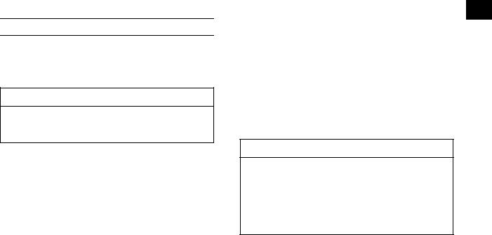
Oil Level Inspection
•If the oil has just been changed, let the motorcycle sit a few minutes allowing the oil to settle.
•Start the engine and run it for several minutes at idle speed. Do not run the engine at high engine speed.
•Stop the engine and wait several minutes for the oil to settle.
•Check the engine oil level with the motorcycle vertical through the oil level inspection window on the lower right side of the engine. The oil level should come up between the high and low level lines next to the inspection window.
NOTE
○If the oil level is too high, remove the excess oil using a syringe or other suitable device.
○If the oil level is too low, add the correct amount of oil through the oil filler opening. Use oil of the same type and brand as those of the one that is already in the engine.

NOTE
○If no oil appears in the oil level inspection window, tip the motorcycle slightly to the right until oil is visible then return to an upright position. If no oil appears even when tipped at an extreme angle, remove the drain bolt to empty any oil that may be in the transmission and crankcase, reinstall the drain bolt and refill with the specified amount of oil.
|
MAINTENANCE AND ADJUSTMENT 39 |
||
|
• Warm up the engine thoroughly so that the oil will |
||
|
pick up any sediment and drain easily. |
||
|
• Stop the engine, and place a container beneath it. |
||
|
j |
||
|
• Remove the oil filler plug. |
||
|
• Remove the oil drain bolt and position the vehicle |
||
|
perpendicular to the ground to allow all the oil to |
||
|
drain. |
||
A.Oil Level Inspection Window
B.High Level Line
C.Low Level Line
D.Oil Filler Plug
Oil and/or Oil Filter Change
The engine oil and/or oil filter should be changed periodically to ensure long engine life.
A. Drain Bolt
 WARNING
Engine oil is a toxic substance. Dispose of used oil properly. Contact your local authorities for approved disposal methods or possible recycling.
![]()
40 MAINTENANCE AND ADJUSTMENT
•When the oil filter is replaced, remove the oil filter cap bolts and take off the cap with O-ring and
 j spring.
•Replace the oil filter element with a new one.
•Apply grease to the grommet.
•Install the oil filter element with the grommet toward the engine.
NOTICE
Inside-out installation stop oil flow, causing engine seizure.
A.Oil Filter Cap Bolts
B.Oil Filter Cap
A. Oil Filter Element
B. Grommet

•Install the spring to the oil filter cap.
•Install the oil filter cap with the grease applied to a new O-ring and tighten its bolts to the specified torque.
A.Spring
B.O-ring
C.Oil Filter Cap
Tightening Torque
Oil Filter Cap Bolts:
9.8N·m (1.0 kgf·m, 87 in·lb)
•After the oil has completely drained out, install the drain bolt with its new gasket. Proper torque for it is shown in the table.
|
MAINTENANCE AND ADJUSTMENT 41 |
||
|
Tightening Torque |
||
|
Engine Oil Drain Bolt: |
||
|
20 N·m (2.0 kgf·m, 15 ft·lb) |
j |
|
|
NOTE |
||
|
○Replace the gasket and O-ring with a new one. |
•Fill the engine up to the high level line with good quality engine oil specified in the table.
Recommended Engine Oil
Castrol “Power1 Racing 4T” 5W-40 or “Kawasaki Performance 4-Stroke Full Synthetic Oil*” 10W-40 or
“Kawasaki Performance 4-Stroke Semi-Synthetic Oil*” 10W-40 or
“Kawasaki Performance 4-Stroke Motorcycle Oil*” 10W-40
*Kawasaki Performance Oils and Lubricants have been specifically engineered for your vehicle. Consistent use of these products meets or exceeds service requirements and can help to extend the life of your Kawasaki.
Engine Oil Capacity
Capacity:
0.75 L (0.79 US qt) (When filter is not removed) 0.80 L (0.85 US qt) (When filter is removed) 1.0 L (1.1 US qt) (When engine is completely dry)

|
42 MAINTENANCE AND ADJUSTMENT |
|||
|
NOTE |
|||
|
○If unavailable, use equivalent engine oil in accor- |
|||
|
j |
|||
|
dance with the following table. |
|||
|
Type: |
|||
|
API SG, SH, SJ, SL or SM with JASO MA, MA1 |
|||
|
or MA2 |
|||
|
Viscosity: |
|||
|
SAE 10W-30, 10W-40, 10W-50 |
|||
|
NOTE |
|||
|
○Do not add any chemical additive to the oil. Oils |
|||
|
fulfilling the above requirements are fully formu- |
|||
|
lated and provide adequate lubrication for both the |
|||
|
engine and the clutch. |
The oil viscosity may need to be changed to accommodate atmospheric conditions in your riding area.
• Tighten the oil filler plug.
Tightening Torque
Oil Filler Plug:
3.5N·m (0.36 kgf·m, 31 in·lb)
•Start the engine.
•Check the oil level and oil leakage.

Cooling System
Water Hoses
Check the water hoses for cracks or deterioration, and the connections for looseness in accordance with the Periodic Maintenance Chart.
Radiator
Check the radiator fins for obstruction by insects or mud. Clean off any obstructions with a low-pressure stream of water.
NOTICE
Using high-pressure water, as from a car wash facility, could damage the radiator fins and impair the radiator’s effectiveness.
Do not obstruct or deflect airflow by installing unauthorized accessories in front of the radiator.
Interference with the cooling airflow can lead to overheating and consequent engine damage.
Coolant
Coolant absorbs excessive heat from the engine and transfers it to the air through the radiator. If the coolant level becomes low, the engine overheats and may suffer severe damage. Check the coolant level each day before riding the motorcycle, and replenish coolant if the level is low.
MAINTENANCE AND ADJUSTMENT 43
 WARNING
The cooling system can get extremely hot
during normal operation and cause serious j burns. Do not touch the radiator when it is
hot, nor open the radiator cap. Hot coolant inside will cause severe burns.
NOTE
○The coolant originally filled into the cooling system contains 50% of a permanent, ethylene-glycol -based antifreeze, has a freezing point of –35°C (–31°F) and a green appearance.
Coolant Level Inspection
• Remove the bolts and right radiator shroud.
A.Bolts
B.Right Radiator Shroud

44 MAINTENANCE AND ADJUSTMENT
•Situate the motorcycle perpendicular to the ground until the radiator cap is level to the ground,
|
j |
so that the radiator |
cap is located uppermost |
|
|
in order to exhaust |
the air accumulated in the |
||
radiator.
•Remove the radiator cap in two steps.
•First, turn the cap counterclockwise to the first stop and wait there for a few seconds.
•Then, push and turn the cap further in the same direction and remove it.
A.Radiator Cap
•Check the coolant level in the radiator. The coolant should come up to the bottom of the radiator filler neck.
NOTE
○Check the coolant level when the engine is cold (room or ambient temperature).
A.Coolant Level
B.Filler Neck
•If the coolant level is low, add coolant through the radiator filler opening to the bottom of the filler neck.
Water and Antifreeze Mixing Ratio
1:1 (water:antifreeze)
Recommended Antifreeze
Permanent type of antifreeze (ethylene glycol plus corrosion and rust inhibitor chemicals for aluminum engines and radiators)
Coolant Total Amount
1.2 L (1.3 US qt)

|
MAINTENANCE AND ADJUSTMENT 45 |
|||
|
• Install the radiator cap. |
|||
|
• Temporarily tighten the radiator shroud bolts fol- |
|||
|
lowing the tightening sequence. |
j |
||
• Tighten the radiator shroud bolts securely.
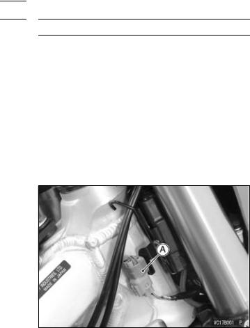
Coolant Change
The coolant should be changed to ensure long engine life, if necessary.
•Wait for the engine to cool completely.
•Situate the motorcycle perpendicular to the ground until the radiator cap is level to the ground.
•Remove the radiator cap in two steps.
•Drain the coolant from the engine and radiator in the following way.
•Place a container under the coolant drain bolt on the water pump cover and remove the drain bolt.
A. Coolant Drain Bolt
NOTICE
Immediately wash away any coolant that spills on the frame, engine, or wheel.
 WARNING
Coolant on tires will make them slippery and can cause loss of traction resulting in an accident and injury. Thoroughly clean any coolant that might have splashed on the tires.
•Visually inspect the old coolant.
•If whitish cotton-like wafts are observed, aluminum parts in the cooling system are corroded and the system must be flushed.
|
46 MAINTENANCE AND ADJUSTMENT |
|||
|
• If the coolant is brown, iron or steel parts are rust- |
|||
|
ing and the system must be flushed. |
|||
|
• Check the cooling system for damage, loose con- |
|||
|
j |
|||
|
nections, and leaks. |
|||
|
• Install the coolant drain bolt with its new gasket |
|||
|
at the water pump cover and apply the specified |
|||
|
torque. |
|||
|
NOTE |
|||
|
○Always replace a gasket with a new one. |
|||
|
Tightening Torque |
|||
|
Coolant Drain Bolt: |
|||
|
7.0 N·m (0.71 kgf·m, 62 in·lb) |
|||
|
• Fill the radiator up to the bottom of the radiator filler |
|||
|
neck with coolant. |
|||
|
• Lean the motorcycle slightly until the radiator filler |
|||
|
neck is level to the ground so that the filler neck |
|||
|
is located uppermost in order to exhaust the air |
|||
|
accumulated in the radiator. |
|||
|
NOTICE |
|||
|
Use coolant containing corrosion inhibitors |
|||
|
made specifically for aluminum engines and |
|||
|
radiators in accordance with the instruction |
|||
|
of the manufacture. Soft or distilled water |
|||
|
must be used with the antifreeze in the cool- |
|||
|
ing system. If hard water is used in the sys- |
|||
|
tem, it causes scale accumulation in the wa- |
|||
|
ter passages, and considerably reduces the |
|||
|
efficiency of the cooling system. |
NOTE
○Pour in the coolant slowly so that it can expel the air from the engine and radiator.
•Install the radiator cap.
•Check the cooling system for leaks.
•Start the engine and warm up thoroughly, then stop it.
•Check the coolant level after the engine has cooled down. The coolant should come up to the bottom of the radiator filler neck.
•If the coolant level is low, add coolant up to the bottom of the radiator filler neck.
•Install the radiator cap.
•Check the cooling system for leaks.

Spark Plug
The spark plug should be taken out periodically for inspection and regapping. Measure the gap with a wire-type thickness gauge. If incorrect, adjust the gap to the specified value by bending the outer electrode.
Spark Plug Gap
CPR8EB-9
0.8 0.9 mm (0.031 0.035 in.)
CPR9EB-9
A.Gap
B.Outer Electrode
MAINTENANCE AND ADJUSTMENT 47
If the plug is oily or has carbon built up on it, clean it. The plug may also be cleaned using a high flash
-point solvent and a nonmetal brush (nylon etc.). If j the spark plug electrodes are corroded, or damaged,
or if the insulator is cracked, replace the plug. The standard spark plug is shown in the table below.
Standard Spark Plug
NGK CPR8EB-9
To find out whether the plug’s heat range is correct, remove the plug and examine the ceramic insulator around the center electrode. If the ceramic is light brown, the spark plug correctly matches the engine temperature.
If the ceramic is burned white, the plug should be replaced with a colder plug.
Optional Spark Plug
NOTE
○If the engine performance drops, try replacing the spark plug to regain performance.
Spark Plug Removal and Installation
•Remove the seat (see Air Cleaner section).
•Remove the bolts and take off the radiator shroud on both sides.

48 MAINTENANCE AND ADJUSTMENT
• Remove the fuel tank mounting bolt and band.
 j
j
A. Bolts
B. Radiator Shroud
A. Fuel Tank Mounting Bolt
B. Band

•Be sure to place a piece of cloth around the fuel hose joint.
•Wipe off the dirt of the surface around the connection using a cloth or a soft brush.
•Insert a thin blade screwdriver into the slit on the joint lock.
MAINTENANCE AND ADJUSTMENT 49
 WARNING
Fuel is flammable and explosive under cer-
tain conditions and can cause severe burns. j Be prepared for fuel spillage; any spilled
fuel must be completely wiped up immediately. When the fuel hose is disconnected, fuel spills out from the hose and the pipe because of residual pressure. Cover the hose connection with a piece of clean cloth to prevent fuel spillage.
A.Cloth
B.Thin Blade Screwdriver
C.Joint Lock