Решил поделится мануалом для Dodge Ram 1500 02-09гг. Найден на просторах интернета.
Иногда бывает найти проблематично, особенно когда не знаешь где искать, а главное как искать.
Быть может кому-то это облегчит немножко жизнь.
Полный мануал для 1500 кузова 3 поколения с
двигателями —3,7l —4,7l —5,7l —5,9lDiesel
мкпп — NV3500, NV4500, NV5600
акпп — 48RE, 45RFE, 545RFE
раздатки — NV241 GENII, NV271, NV243, NV244 GENII, NV273
Dodge Ram 1500 02-09 Service Manual 89 Mb
Перевод раздела с двигателем 4.7
Dodge 4.7 Magnum RUS 4 Mb
Данную запись буду пополнять по возможности.
*информация для личного пользования
- Manuals
- Brands
- RAM Manuals
- Trucks
- 1500 2019
- User manual
-
Contents
-
Table of Contents
-
Troubleshooting
-
Bookmarks
Quick Links
Chapters
-
Getting to Know Your Vehicle
11 -
Getting to Know Your Instrument Panel
75 -
Safety
93 -
Starting and Operating
143 -
In Case of Emergency
197 -
Servicing and Maintenance
225 -
Technical Specifications
251 -
Multimedia
257
Related Manuals for RAM 1500 2019
Summary of Contents for RAM 1500 2019
-
Page 1
USER GUIDE… -
Page 2
IMPORTANT Get warranty and other information online – you can review and print or download a copy of the Owner’s Manual, Navigation/ Uconnect manuals and the limited warranties provided by FCA US LLC for your vehicle by visiting www.mopar.com (U.S.) or www.owners.mopar.ca (Canada). -
Page 3
Congratulations on selecting your new FCA ments to its products without imposing any This User Guide is not a replacement for the full Owner’s Manual, and does not fully cover every US LLC vehicle. Be assured that it represents obligation upon itself to install them on prod- operation and procedure possible with your ve- precision workmanship, distinctive styling, ucts previously manufactured. -
Page 4
HOW TO USE THIS MANUAL Chapters can be rapidly identified with dedi- ment installed by van conversion/camper cated graphic tabs, at the side of each odd manufacturers/body builders. U.S. residents Essential Information page. A few pages further there is a key for refer to the Warranty Information book, Sec- getting to know the chapter order and the tion 2.1.C. -
Page 5
GRAPHICAL TABLE OF CONTENTS GETTING TO KNOW YOUR VEHICLE GETTING TO KNOW YOUR INSTRUMENT PANEL SAFETY STARTING AND OPERATING IN CASE OF EMERGENCY SERVICING AND MAINTENANCE TECHNICAL SPECIFICATIONS MULTIMEDIA CUSTOMER ASSISTANCE INDEX… -
Page 7
GRAPHICAL TABLE OF CONTENTS GRAPHICAL TABLE OF CONTENTS INSTRUMENT PANEL … . .6 INTERIOR…..7… -
Page 8
INSTRUMENT PANEL Instrument Panel 1 — Air Vents 4 — Uconnect System 2 — Instrument Cluster Display Controls 5 — Climate Controls 3 — Instrument Cluster 6 — Switch Panel… -
Page 9
INTERIOR Interior 1 — Steering Wheel 3 — Gear Selector 2 — Seats 4 — Glove Compartment… -
Page 11: Table Of Contents
GETTING TO KNOW YOUR VEHICLE GETTING TO KNOW YOUR VEHICLE KEYS ….. .11 Ventilated Seats — If Equipped ..23 High/Low Beam Switch .
-
Page 12
Climate Controls With A Touchscreen GARAGE DOOR OPENER — RamBox Integrated Box Side Storage Overview ….38 Bins ….. . .64 IF EQUIPPED . -
Page 13: Keys
Ram- The key fob allows you to lock or unlock all Box (if equipped). The turn signal lights will doors, tailgate, and the RamBox (if equipped) flash to acknowledge the unlock signal.
-
Page 14
To Lock The Doors And Tailgate • You may need to be less than 35 ft (11 m) Canceling Remote Lowering from the vehicle when using the key fob to Vehicle lowering can be cancelled at any- Push and release the lock button on the key turn off the Panic Alarm due to the radio time. -
Page 15: Ignition Switch
General Information IGNITION SWITCH The following regulatory statement applies to Keyless Push Button Ignition all radio frequency (RF) devices equipped in this vehicle: This feature allows the driver to operate the ignition switch with the push of a button as This device complies with Part 15 of the FCC long as the Remote Keyless Entry key fob is in Rules and with Industry Canada license-…
-
Page 16
The push button ignition can be placed in the In case the ignition switch does not change WARNING! following modes: with the push of a button, the key fob may reasons. A child or others could be seri- have a low or dead battery. In this situation, a ously or fatally injured. -
Page 17: Remote Start — If Equipped
NOTE: NOTE: To Exit Remote Start Mode The key fob may not be able to be detected by Without Driving The Vehicle • If your power door locks were unlocked, the vehicle keyless-go system if it is located Remote Start will automatically lock the Push and release the remote start button one next to a mobile phone, laptop or other elec- doors.
-
Page 18: General Information
General Information VEHICLE SECURITY ALARM 2. Perform one of the following methods to lock the vehicle: The following regulatory statement applies to The vehicle security alarm monitors the ve- • Push lock button on the interior power all radio frequency (RF) devices equipped in hicle doors, tailgate, and ignition for unau- door lock switch with the driver and/or this vehicle:…
-
Page 19: To Disarm The System
To Disarm The System If the vehicle security alarm is armed and the the touchscreen. When configured for “Stow” battery becomes disconnected, the vehicle mode, the steps will stay in their position but The vehicle security alarm can be disarmed security alarm will remain armed when the can also be deployed manually through the using any of the following methods:…
-
Page 20
• If wearing gloves on your hands, or if it has To Unlock From The Passenger Side: been raining/snowing on the Passive Entry With a valid Passive Entry key fob within 5 ft door handle, the unlock sensitivity can be (1.5 m) of the passenger door handle, grab affected, resulting in a slower response time. -
Page 21
If one of the vehicle doors is open and the door panel switch is used to lock the vehicle, once all open doors have been closed the vehicle checks the inside and outside of the vehicle for any valid Passive Entry key fobs. If one of the vehicle’s Passive Entry key fobs is detected inside the vehicle, and no other valid Passive Entry key fobs are detected… -
Page 22: Seats
• The Passive Entry system will not operate if Driver Memory Seats — If the key fob battery is dead. Equipped The vehicle doors can also be locked by using This feature allows the driver to store up to the key fob lock button or the lock button two different memory profiles for easy recall located on the vehicle’s interior door panel.
-
Page 23
3. Push and release the set (S) button on the Refer to “Uconnect Settings” in “Multime- NOTE: memory switch. dia” in your Owner’s Manual for further infor- Your key fobs can be unlinked to your memory mation. settings by pushing the set (S) button, and 4. -
Page 24: Heated Seats — If Equipped
• To recall the memory settings for driver two • When you remove the key fob from the Heated Seats — If Equipped using the key fob, push the unlock button ignition, the driver’s seat will move to a On some models, the front and rear seats may on the key fob linked to memory position 2.
-
Page 25: Ventilated Seats — If Equipped
Front Heated Seats This feature can be programmed through the NOTE: Uconnect system. Refer to “Uconnect Set- • The level of heat selected will stay on until The heated seats control buttons are located tings” in “Multimedia” in your Owner’s the operator changes it.
-
Page 26: Head Restraints
• Press the ventilated seat button There are two ventilated seat switches that WARNING! second time to choose MED. allow the rear passengers to operate the seats independently. The fans operate at three • All occupants, including the driver, • Press the ventilated seat button a third speeds: HI, MED, and LO.
-
Page 27: Front Head Restraints
Front Head Restraints WARNING! Your vehicle is equipped with front four way • All occupants, including the driver, driver and passenger head restraints. should not operate a vehicle or sit in a To raise the head restraint, pull upward on the vehicle’s seat until the head restraints are placed in their proper positions in head restraint.
-
Page 28: Steering Wheel
The center head restraint is not adjustable or removable. NOTE: The head restraints should only be removed by qualified technicians, for service purposes only. If any of the head restraints require removal, see an authorized dealer. For child restraint tethering, refer to “Occu- pant Restraints”…
-
Page 29: Heated Steering Wheel — If Equipped
• Press the heated steering wheel button WARNING! WARNING! once to turn the heating element on. wheel heater. It may cause burns even at Do not adjust the steering column while • Press the heated steering wheel button low temperatures, especially if used for driving.
-
Page 30: Mirrors
The adjustable pedal switch is located on the is locked out: “Adjustable Pedal Disabled CAUTION! instrument panel, below the headlight switch. — Cruise Control Engaged” or “Adjustable Pedal Disabled — Vehicle In Reverse”. Do not place any article under the adjust- able pedals or impede its ability to move, NOTE: as it may cause damage to the pedal con-…
-
Page 31
If the mirror is manually folded after electri- Resetting The Power Folding Outside Mirrors NOTE: cally cycled, a potential extra button push is • The power fold mirrors are designed to You may need to reset the power folding required to get the mirrors back to the home operate while the vehicle is stationary or mirrors if the following occurs: position. -
Page 32: Trailer Towing Mirrors — If Equipped
Trailer Towing Mirrors — If NOTE: slightly downward from the present position Fold the trailer towing mirrors rearward prior when the vehicle is shifted into REVERSE. Equipped to entering an automated car wash. The outside mirrors will then return to the These mirrors are designed with an adjust- original position when the vehicle is shifted A small blindspot mirror is located next to…
-
Page 33: Exterior Lights
EXTERIOR LIGHTS Rotate the headlight switch clockwise to the first detent for parking light and instrument Headlight Switch panel light operation. Rotate the headlight switch to the second detent for headlight, The headlight switch is located on the left parking light, and instrument panel light op- side of the instrument panel.
-
Page 34: High/Low Beam Switch
Multifunction Lever Automatic High Beam Headlamp • Broken, muddy, or obstructed headlights and taillights of vehicles in the field of view Control — If Equipped The multifunction lever is located on the left will cause headlights to remain on longer side of the steering column.
-
Page 35: Flash-To-Pass
2. Turn the headlight switch to the AUTO Flash-To-Pass Parking Lights And Panel Lights headlight position. You can signal another vehicle with your To turn on the parking lights and 3. Push the multifunction lever away from instrument panel lights, from the headlights by lightly pulling the multifunc- you (toward front of vehicle) to engage the O (off) position, rotate the head-…
-
Page 36: Headlight Delay
Headlight Delay Front Fog Lights — If Equipped Turn Signals To aid in your exit, your vehicle is equipped To activate the front fog lights, turn on the Move the multifunction lever up or down and with a headlight delay that will leave the parking lights or low beam headlights and the arrows on each side of the instrument headlights on for approximately up to 90 sec-…
-
Page 37: Battery Saver
If the ignition is OFF and any door is left ajar for 10 minutes or the dimmer control is rotated all the way up to the dome on position for 10 minutes, the interior lights will auto- matically turn off. NOTE: Battery saver mode is canceled if the ignition is ON.
-
Page 38
pause between cycles, desirable. For maxi- To prevent freeze-up of your windshield mum delay between cycles, rotate the control washer system in cold weather, select a solu- knob upward to the first detent. tion or mixture that meets or exceeds the temperature range of your climate. -
Page 39: Rain Sensing Wipers — If Equipped
NOTE: NOTE: • Low Ambient Temperature — When the igni- tion is first turned ON, the Rain Sensing The mist feature does not activate the washer Position 3 should be used for normal rain system will not operate until the wiper pump;…
-
Page 40: Climate Controls
CLIMATE CONTROLS Climate Controls With A Touchscreen Overview Uconnect 4/4C/4C NAV With 8.4–inch Display Automatic Climate Controls…
-
Page 41
Uconnect 4C NAV With 12–inch Display Automatic Climate Controls… -
Page 42
Uconnect 4C/4C NAV With 8.4–inch Display Automatic Climate Control Knobs… -
Page 43
Control Descriptions NOTE: Icons and descriptions can vary based upon vehicle equipment. Icon Description MAX A/C Touchscreen: Press and release to change the current setting, the indicator illuminates when MAX A/C is on. Performing this function again will cause the MAX A/C operation to switch into manual mode and the MAX A/C indicator will turn off. -
Page 44
Icon Description AUTO Control Knob AUTO — If Equipped Automatically controls the interior cabin temperature by adjusting airflow distribution and amount. Toggling this func- tion will cause the system to switch between manual mode and automatic modes. AUTO Button Refer to “Automatic Operation” within this section for more information. Front Defrost Button Press and release the touchscreen button, or push and release the button on the faceplate, to change the current airflow setting to Defrost mode. -
Page 45
Icon Description Driver and Passenger Temperature Up and Down Buttons Faceplate or Touchscreen: Provides the driver and passenger with independent temperature control. Push the up arrow button on the faceplate, press the up arrow button on the touchscreen, or press and slide the temperature bar towards the red arrow button on the touchscreen for warmer temperature settings. -
Page 46
Icon Description Mode Control Knob Modes Control Control Knob: Push the Mode Control Knob to change the airflow distribution mode. The airflow distribution mode can be adjusted so air comes from the instrument panel outlets, floor outlets, defrost outlets and demist outlets. Touchscreen: Press the “MODE”… -
Page 47: Climate Control Functions
Icon Description Mix Mode Mix Mode Air is directed through the floor, defrost, and side window demister outlets. This setting works best in cold or snowy con- ditions that require extra heat to the windshield. This setting is good for maintaining comfort while reducing moisture on the windshield.
-
Page 48: Automatic Temperature Control (Atc) — If Equipped
Recirculation 2. Next, adjust the temperature you would warms up. The blower will increase in speed like the system to maintain by adjusting and transition into Auto mode. When outside air contains smoke, odors, or the driver and passenger temperature high humidity, or if rapid cooling is desired, Manual Operation Override control buttons.
-
Page 49: Power Sunroof — If Equipped
Vacation/Storage POWER SUNROOF — IF EQUIPPED CAUTION! Before you store your vehicle, or keep it out of mild washing solution, wiping parallel Single Pane Power Sunroof — If service (i.e., vacation) for two weeks or more, to the heating elements. Labels can be Equipped run the air conditioning system at idle for peeled off after soaking with warm…
-
Page 50
Opening Sunroof will close fully and stop automatically. This is WARNING! called “Express Close.” During Express Close Express operation, any other actuation of the switch • Never leave children unattended in a Push the switch rearward and release it will stop the sunroof. vehicle, or with access to an unlocked within one-half second. -
Page 51
If the buffeting occurs with the sunroof open, Venting Sunroof — Express Relearn Procedure adjust the sunroof opening to minimize the Push and release the Vent button within one For vehicles equipped with a sunroof, there is buffeting or open any window. half second and the sunroof will open to the a relearn procedure that allows you to cali- vent position. -
Page 52: Dual Pane Power Sunroof — If Equipped
6. Once the sunroof has stopped in the fully Opening Sunroof WARNING! closed position, release the close switch. The sunroof has two programmed open posi- The sunroof is now reset and ready to use. • Never leave children unattended in a tions, comfort stop position and full open po- Dual Pane Power Sunroof —…
-
Page 53
to the full open position and automatically Manual and stop automatically. This is called “Ex- stop. Any release of the switch will stop the press Open”. During Express Open operation, To close the sunroof, push and hold the switch sunroof movement. The sunroof will remain any movement of the sunshade switch will in the forward position. -
Page 54
Express Pinch Protect Feature If the buffeting occurs with the sunroof open, adjust the sunroof opening to minimize the Push the sunshade switch forward and re- This feature will detect an obstruction in the buffeting or open any window. lease it within one-half second. If the sunroof closing of the sunroof during the Express Sunroof Maintenance is in closed position the sunshade will full… -
Page 55: Hood
HOOD 2. Reach into the opening beneath the cen- WARNING! ter of the hood and push the safety latch To Open The Hood lever to the left to release it, before raising Be sure the hood is fully latched before the hood.
-
Page 56: Closing
Electronic Tailgate Release — If Equipped GARAGE DOOR OPENER — IF WARNING! EQUIPPED • Your motorized door or gate will open The key fob may be equipped and close while you are programming with an electronic release fea- HomeLink replaces up to three hand-held the universal transceiver.
-
Page 57: Before You Begin Programming Homelink
tures. Call toll-free 1-800-355-3515 or, on tion with the Engine ON. Make sure while NOTE: the Internet at HomeLink.com for safety in- programming HomeLink with the engine For vehicles equipped with Keyless Enter- ON that your vehicle is outside of your formation or assistance.
-
Page 58: Programming A Non-Rolling Code
5. At the garage door opener motor (in the To program the remaining two HomeLink 2. Place the hand-held transmitter 1 to garage), locate the “LEARN” or “TRAIN- buttons, repeat each step for each re- 3 inches (3 to 8 cm) away from the maining button.
-
Page 59: Canadian/Gate Operator Programming
Reprogramming A Single HomeLink Button signal during programming. Similar to this 3. Push and hold the HomeLink button while Canadian law, some U.S. gate operators are you push and release (“cycle”), your (Non-Rolling Code) designed to time-out in the same manner. hand-held transmitter every two seconds.
-
Page 60: Using Homelink
Reprogramming A Single HomeLink Button Using HomeLink Troubleshooting Tips (Canadian/Gate Operator) If you are having trouble programming To operate, push and release the pro- To reprogram a channel that has been previ- HomeLink, here are some of the most com- grammed HomeLink button.
-
Page 61: General Information
General Information INTERNAL EQUIPMENT CAUTION! The following regulatory statement applies to in the power outlets as this will damage Electrical Power Outlets all Radio Frequency (RF) devices equipped in the outlet and blow the fuse. Improper this vehicle: The auxiliary 12 Volt (13 Amp) power outlet use of the power outlet can cause dam- can provide power for in-cab accessories de- age not covered by your New Vehicle…
-
Page 62
Power Outlet Fuse Locations 1 — F54 Fuse 20 A Yellow Power Outlet Battery Fed Position 2 — F54 Fuse 20 A Yellow Power Outlet Ignition Fed Position 3 — F48 Fuse 10 A Red Port Power or Rear USB (Charge Only) -
Page 63: Power Inverter — If Equipped
When the vehicle is turned off, be sure to CAUTION! unplug any equipment as to not drain the to degrade battery life and/or prevent the battery of the vehicle. All accessories con- engine from starting. nected to the outlet(s) should be removed or •…
-
Page 64
If equipped, a 115 Volt (400 Watts Maxi- To turn on the power outlet, simply plug in mum) inverter may be located inside the ram the device. The outlet turns off when the box of your vehicle. This inverter can power device is unplugged. -
Page 65: Wireless Charging Pad — If Equipped
NOTE: Wireless Charging Pad — If NOTE: Avoid placing key fob within 6 in (15 cm) of Equipped • The Power Inverter only turns on if the the Wireless Charging Pad Module to prevent ignition is in the ACC or ON/RUN position. interference with key fob detection.
-
Page 66: Pickup Box
PICKUP BOX There are four tie-down cleats bolted to the WARNING! lower sides of the pickup box that can sustain reduced. Severe turns or rough roads The pickup box has many features designed loads up to 1000 lbs (450 kg) total. may cause shifting or bouncing of the for utility and convenience.
-
Page 67
The interior of the RamBox will automatically Locking And Unlocking RamBox CAUTION! illuminate when the lid is opened. The timing Push and release the lock or unlock button on can be adjusted through your touchscreen. Failure to follow the following items could the key fob to lock and unlock all doors, the cause damage to the vehicle: Refer to “Uconnect Settings”… -
Page 68: Rambox Safety Warning
Bed Extender — If Equipped CAUTION! WARNING! The bed extender has three functional posi- to minimize potential for damage, se- • Do not drive the vehicle with the storage tions: cure all cargo to prevent movement and bin covers open. •…
-
Page 69
3. Rotate the side gates closed allowing the 3. Rotate the side gates closed so that the 3. Fit the end of the side gate ends onto the pin and handle. outboard ends to be positioned in front of outboard ends are secured into the in- the cargo tie down loops. -
Page 70: Bed Rail Tie-Down System
Bed Rail Tie-Down System To remove the cleats from the utility rail, NOTE: When a cap or pickup camper is installed on remove the end cap screw located in the a vehicle, an alternate Center High-Mounted center of the end cap, using a #T30 Torx CAUTION! Stop Light (CHMSL) must be provided.
-
Page 71: Removing The Tailgate
4. Connect the chassis plug and bracket NOTE: TRI-FOLD TONNEAU COVER — IF (provided in the glove compartment) to EQUIPPED Make sure tailgate is supported when the chassis wiring harness and insert the removing support cables. bracket back into the sill. Your vehicle may be equipped with a Tri-Fold 3.
-
Page 72: Tri-Fold Tonneau Cover Installation
3. Push clamp wires up and under the flange both driver and passenger sides to the clamp up into the proper released of box (or flange of Ram Box rail, if semi clamped position. position. equipped) to the semi clamped position.
-
Page 73: Tri-Fold Tonneau Cover Cleaning
9. Push clamp wires up and under the flange Tri-Fold Tonneau Cover Cleaning of box (or flange of Ram Box rail, if For proper cleaning of the Tonneau Cover, use equipped) to the semi clamped position. Mopar Whitewall & Vinyl Top Cleaner and 10.
-
Page 75
GETTING TO KNOW YOUR INSTRUMENT PANEL GETTING TO KNOW YOUR INSTRUMENT PANEL INSTRUMENT CLUSTER DISPLAY ..74 WARNING LIGHTS AND MESSAGES ..77 Blue Indicator Lights … . .88 Red Warning Lights . -
Page 76: Instrument Cluster Display
INSTRUMENT CLUSTER DISPLAY Instrument Cluster Display The system allows the driver to select infor- mation by pushing the following instrument Controls Your vehicle will be equipped with an instru- cluster display control buttons located on the ment cluster display, which offers useful in- left side of the steering wheel: The instrument cluster display features a formation to the driver.
-
Page 77: Oil Life Reset
Left And Right Arrow Buttons: • Within each submenu layer, the up and NOTE: down arrows will allow the user to select the Use the steering wheel instrument cluster Using the left or right arrow button allows you item of interest. display controls for the following procedure: to cycle through the submenu items of the •…
-
Page 78: Battery Saver On/Battery Saver Mode Message — Electrical Load Reduction Actions — If Equipped
NOTE: When load reduction is activated, the mes- • 115V AC Power Inverter System If the indicator message illuminates when sage “Battery Saver On Some Systems May • Audio and Telematics System Have Reduced Power” will appear in the you start the vehicle, the Oil Life indicator Loss of the battery charge may indicate one system did not reset.
-
Page 79: Warning Lights And Messages
• The battery was discharged by an electrical review specifications if any (load and Igni- Red Warning Lights load left on when the vehicle was parked. tion Off Draw currents). — Seat Belt Reminder Warning Light • The battery was used for an extended pe- •…
-
Page 80
— Brake Warning Light the Brake Warning Light, which will turn on Operation of the Brake Warning Light can be checked by turning the ignition switch from when the brake fluid level in the master cylin- This light monitors various brake functions, the OFF position to the ON/RUN position. -
Page 81
— Vehicle Security Warning Light — If — Battery Charge Warning Light — Electronic Throttle Control (ETC) Equipped Warning Light This light illuminates when the battery is not charging properly. If it stays on while the This light will flash at a fast rate for approxi- This warning light will illuminate to inform of engine is running, there may be a malfunc- mately 15 seconds when the vehicle security… -
Page 82
remain on briefly as a bulb check. If the light — Tailgate Open Warning Light WARNING! does not come on during starting, have the This indicator will turn when the tailgate is fluid to boil over, come in contact with hot system checked by an authorized dealer. -
Page 83: Yellow Warning Lights
Yellow Warning Lights engine start. If the bulb does not come on WARNING! when turning the ignition switch from OFF to — Adaptive Cruise Control (ACC) Fault This could result in death or serious injury ON/RUN, have the condition checked to the driver, occupants or others.
-
Page 84
— Electronic Stability Control (ESC) • This light will come on when the vehicle is • Refer to “LaneSense – If Equipped» in “Starting And Operating” for further in an ESC event. Active Warning Light — If Equipped information. This light will indicate when the Electronic —… -
Page 85
— Tire Pressure Monitoring System vehicle placard or tire inflation pressure la- Your vehicle has also been equipped with a bel. (If your vehicle has tires of a different TPMS malfunction indicator to indicate when (TPMS) Warning Light size than the size indicated on the vehicle the system is not operating properly. -
Page 86
required as soon as possible. However, the — Service Stop/Start System Warning CAUTION! conventional brake system will continue to Light — If Equipped TPMS pressures and warning have been operate normally, assuming the Brake Warn- This warning light will illuminate when the established for the tire size equipped on ing Light is not also on. -
Page 87: Yellow Indicator Lights
Yellow Indicator Lights — TOW/HAUL Indicator Light — Air Suspension Normal Height Indicator Light— If Equipped This indicator light will illuminate when TOW/ — Forward Collision Warning Off Indi- HAUL mode is selected. This light will illuminate when the air suspen- cator Light —…
-
Page 88: Green Indicator Lights
— Air Suspension — 4WD Low Indicator Light — If — NEUTRAL Indicator Light — If Equipped Ride Height Raising Indicator Light— If Equipped Equipped This light alerts the driver that the 4WD This light alerts the driver that the vehicle is power transfer case is in the NEUTRAL mode This light will blink and alert the driver that the in the four-wheel drive LOW mode.
-
Page 89
Refer to «Adaptive Cruise Control (ACC) — If — Front Fog Indicator Light — If — Speed Control SET Indicator Light Equipped» in «Starting And Operating» for Equipped — If Equipped With 7 Inch Instrument Clus- ter Display further information. This indicator light will illuminate when the front fog lights are on. -
Page 90: White Indicator Lights
For further information on four-wheel drive Refer to “Speed Control” in “Starting And Refer to “LaneSense — If Equipped» in operation and proper use, refer to “Four- “Starting And Operating” for further informa- Operating” for further information. Wheel Drive Operation — If Equipped” in tion.
-
Page 91: Onboard Diagnostic System
ONBOARD DIAGNOSTIC SYSTEM — CAUTION! WARNING! OBD II • Prolonged driving with the MIL on could • ONLY an authorized service technician cause further damage to the emission should connect equipment to the OBD II Your vehicle is equipped with a sophisticated control system.
-
Page 93
SAFETY SAFETY AUXILIARY DRIVING SYSTEMS ..92 Occupant Restraint Systems SAFETY TIPS ….137 Features ….101 Blind Spot Monitoring (BSM) —… -
Page 94: Auxiliary Driving Systems
AUXILIARY DRIVING SYSTEMS When the vehicle is started, the BSM warning Refer to “Modes Of Operation” in this section light will momentarily illuminate in both out- for further information. Blind Spot Monitoring (BSM) — If side rearview mirrors to let the driver know that the system is operational.
-
Page 95
Rear Cross Path (RCP) When RCP is on and the vehicle is in RE- Blind Spot Alert Lights Only VERSE, the driver is alerted using both the When operating in Blind Spot Alert mode, the The Rear Cross Path (RCP) feature is in- visual and audible alarms, including reduc- tended to aid the driver when backing out of BSM system will provide a visual alert in the… -
Page 96: Forward Collision Warning (Fcw) — If Equipped
NOTE: This device complies with Part 15 of the FCC NOTE: Whenever an audible alert is requested by the Rules and with Industry Canada license- FCW monitors the information from the for- BSM system, the radio is also muted. exempt RSS standard(s). Operation is sub- ward looking sensors as well as the Electronic ject to the following two conditions: Brake Controller (EBC), to calculate the prob-…
-
Page 97
• Changing the FCW status to “off” prevents Medium autonomous braking, or additional brake sup- the system from warning you of a possible port if the driver is not braking adequately in The default status of FCW is the “Medium” collision with the vehicle in front of you. -
Page 98: Tire Pressure Monitoring System (Tpms)
General Information The tire pressure will vary with temperature pressure is at or above the recommended by about 1 psi (7 kPa) for every 12°F (6.5°C). cold placard pressure. Once the low tire pres- The following regulatory statement applies to This means that when the outside tempera- sure warning (Tire Pressure Monitoring [TPM] all Radio Frequency (RF) devices equipped in…
-
Page 99
mately 23 psi (158 kPa). This tire pressure is • The TPMS is not a substitute for proper tire CAUTION! sufficiently low enough to turn on the TPM maintenance, and it is the driver’s respon- your vehicle to an authorized dealership sibility to maintain correct tire pressure Telltale Light. -
Page 100
Premium System Tire Pressure Monitoring Low Pressure Warnings Should this occur, you should stop as soon as possible and inflate the tires with a low pres- The “Tire Pressure Monitoring The Tire Pressure Monitor System (TPMS) sure condition (those in a different color in Telltale Light”… -
Page 101
If the ignition switch is cycled, this sequence ing Telltale Light” will flash on and off for tion, the graphic in the instrument cluster 75 seconds and then remain on solid. The will repeat, providing the system fault still will still display a pressure value in a differ- system fault will also sound a chime. -
Page 102
pressure is below the low-pressure warning The system will be activated when there is • The horn will chirp once again when limit in any of the four active road tires. The over 1.5 psi (10 kPa) of change in tire pres- enough air is let out to reach proper infla- vehicle may need to be driven for up to tion level. -
Page 103: Occupant Restraint Systems
OCCUPANT RESTRAINT SYSTEMS 1. Children 12 years old and under should 7. The driver and front passenger seats always ride buckled up in the rear seat of should be moved back as far as practical Some of the most important safety features in a vehicle with a rear seat.
-
Page 104: Seat Belt Systems
Seat Belt Systems Initial Indication Belt Reminder Light will remain on until the seat belts are buckled. The BeltAlert warning If the driver is unbuckled when the ignition Buckle up even though you are an excellent sequence may repeat based on vehicle speed switch is first in the START or ON/RUN posi- driver, even on short trips.
-
Page 105
BeltAlert can be activated or deactivated by WARNING! WARNING! your authorized dealer. FCA US LLC does not • Be sure everyone in your vehicle is in a recommend deactivating BeltAlert. • Relying on the air bags alone could lead seat and using a seat belt properly. Oc- to more severe injuries in a collision. -
Page 106
Lap/Shoulder Belt Operating Instructions WARNING! WARNING! 1. Enter the vehicle and close the door. Sit • A seat belt that is worn under your arm is • A lap belt worn too high can increase the back and adjust the seat. dangerous. -
Page 107
3. When the seat belt is long enough to fit, Lap/Shoulder Belt Untwisting Procedure insert the latch plate into the buckle until Use the following procedure to untwist a you hear a “click.” twisted lap/shoulder belt. 1. Position the latch plate as close as pos- sible to the anchor point. -
Page 108
NOTE: Seat Belt Extender The adjustable upper shoulder belt anchor- If a seat belt is not long enough to fit properly, age is equipped with an Easy Up feature. This even when the webbing is fully extended and feature allows the shoulder belt anchorage to the adjustable upper shoulder belt anchorage be adjusted in the upward position without (if equipped) is in its lowest position, your… -
Page 109
Position the lap belt snug and low below the Energy Management Feature WARNING! abdomen and across the strong bones of the The front outboard seat belt system is is not long enough and only use in the hips. Place the shoulder belt across the chest equipped with an Energy Management fea- recommended seating positions. -
Page 110
the webbing to retract completely in this case How To Engage The Automatic Locking Mode and then carefully pull out only the amount of 1. Buckle the combination lap and shoulder webbing necessary to comfortably wrap belt. around the occupant’s mid-section. Slide the 2. -
Page 111: Supplemental Restraint Systems (Srs)
with the electrical Air Bag System Compo- ON/RUN position. If the ignition switch is in WARNING! nents. Your vehicle may be equipped with the the OFF position or in the ACC position, the • Failure to replace the seat belt assembly following Air Bag System Components: air bag system is not on and the air bags will could increase the risk of injury in colli-…
-
Page 112
designed to be maintenance free, if any of For additional information regarding the Re- WARNING! the following occurs, have an authorized dundant Air Bag Warning Light refer to “Get- have the air bag system to protect you in a dealer service the air bag system immedi- ting To Know Your Instrument Panel”… -
Page 113
The first stage inflator is triggered immedi- WARNING! ately during an impact that requires air bag including death. Air bags need room to deployment. A low energy output is used in inflate. Sit back, comfortably extending less severe collisions. A higher energy output your arms to reach the steering wheel or is used for more severe collisions. -
Page 114
Front Air Bag Operation A large quantity of non-toxic gas is generated WARNING! to inflate the front air bags. Front Air Bags are designed to provide addi- • No objects should be placed over or near tional protection by supplementing the seat The steering wheel hub trim cover and the the air bag on the instrument panel or upper passenger side of the instrument panel… -
Page 115
Occupant Classification Module (OCM) And • The front passenger seat is occupied by a seat and never install a child restraint sys- Sensor small passenger, including a child; or tem, including a rear-facing child restraint, in the front passenger seat. •… -
Page 116
In order for the OCS to operate as designed, it Lighter Weight Passengers (Including Small passenger’s seated weight on the front pas- is important for the front passenger to be Adults) senger seat may result in a full-power deploy- seated properly and properly wearing the seat ment of the Passenger Advanced Front Air When a lighter weight passenger, including a belt. -
Page 117
• Anything that may decrease or increase the front passenger’s seated weight. The OCS determines the front passenger’s most probable classification. If an occupant in the front passenger seat is seated improp- erly, the occupant may provide an output signal to the OCS that is different from the occupant’s properly seated weight input, for example: Not Seated Properly… -
Page 118
If the Air Bag Warning Light does not • Do not replace the seat cover or cushion WARNING! come on, or stays on after you start the with an aftermarket seat cover or cushion. the center of the seat, with your feet vehicle, or it comes on as you drive, take the •… -
Page 119
Knee Impact Bolsters Supplemental Side Air Bags The Knee Impact Bolsters help protect the Supplemental Seat-Mounted Side Air Bags knees of the driver and front passenger, and (SABs) position the front occupants for improved This vehicle is equipped with Supplemental interaction with the front air bags. -
Page 120
When the SAB deploys, it opens the seam on Supplemental Side Air Bag Inflatable Cur- The SABIC deploys downward, covering the the outboard side of the seatback’s trim tains (SABICs) are located above the side side windows. An inflating SABIC pushes the cover. -
Page 121
The Side Air Bags will not deploy in all side WARNING! WARNING! collisions, including some collisions at cer- the roof. Do not add an aftermarket from the Side Air Bags, occupants must tain angles, or some side collisions that do sunroof to your vehicle. -
Page 122
NOTE: The SABICs may help reduce the risk of If A Deployment Occurs Air bag covers may not be obvious in the partial or complete ejection of vehicle occu- The front air bags are designed to deflate interior trim, but they will open during air bag pants through side windows in certain roll- immediately after deployment. -
Page 123
have skin or eye irritation, rinse the area • After any collision, the vehicle should be Your vehicle may also be designed to perform with cool water. For nose or throat irritation, taken to an authorized dealer immediately. any of these other functions in response to move to fresh air. -
Page 124
electrical devices (e.g. headlights) after an Event Data Recorder (EDR) WARNING! accident, reset the system by following the This vehicle is equipped with an event data instrument panel. Do not modify the procedure described below. recorder (EDR). The main purpose of an EDR front bumper, vehicle body structure, or is to record, in certain crash or near crash- Enhanced Accident Response System Reset… -
Page 125: Child Restraints
NOTE: every Canadian province, requires that small belt. Always check the child seat Owner’s children ride in proper restraint systems. This EDR data are recorded by your vehicle only if Manual to make sure you have the correct is the law, and you can be prosecuted for a non-trivial crash situation occurs;…
-
Page 126
Summary Of Recommendations For Restraining Children In Vehicles Child Size, Height, Weight Or Age Recommended Type Of Child Restraint Children who are two years old or younger and Either an Infant Carrier or a Convertible Child Infants and Toddlers who have not reached the height or weight lim- Restraint, facing rearward in the rear seat of its of their child restraint the vehicle… -
Page 127
Older Children And Child Restraints WARNING! WARNING! Children who are two years old or who have Do not install a rear-facing car seat using a • Improper installation can lead to failure outgrown their rear-facing convertible child rear support leg in this vehicle. The floor of of an infant or child restraint. -
Page 128
Children Too Large For Booster Seats 3. Does the shoulder belt cross the child’s If the shoulder belt contacts the face or neck, shoulder between the neck and arm? move the child closer to the center of the Children who are large enough to wear the vehicle, or use a booster seat to position the 4. -
Page 129
Lower Anchors And Tethers For CHildren positions may have a top tether anchorage but no lower anchorages. In these seating (LATCH) Restraint System positions, the seat belt must be used with the top tether anchorage to install the child re- straint. -
Page 130
Frequently Asked Questions About Installing Child Restraints With LATCH Use the LATCH anchorage system until the combined What is the weight limit (child’s weight + weight of the weight of the child and the child restraint is 65 lbs child restraint) for using the LATCH anchorage system to 65 lbs (29.5 kg) (29.5 kg). -
Page 131
Locating The LATCH Anchorages Locating The Upper Tether Anchorages The lower anchorages are round bars There are tether strap anchorages located that are found at the rear of the seat cushion behind each of the rear seats. where it meets the seatback, below the an- chorage symbols on the seatback. -
Page 132
Center Seat LATCH Crew Cab Split Bench Rear Seat: Center LATCH To Install A LATCH-Compatible Child Re- Anchorages Available straint All Quad Cabs Or Crew Cab Full Bench Rear Seat: No Lower Center LATCH Anchorages Available If a child restraint installed in the center If the selected seating position has a Switch- position blocks the seat belt webbing or able Automatic Locking Retractor (ALR) seat… -
Page 133
3. Attach the lower hooks or connectors of How To Stow An Unused Switchable-ALR WARNING! the child restraint to the lower anchorages (ALR) Seat Belt: in the selected seating position. • Improper installation of a child restraint When using the LATCH attaching system to to the LATCH anchorages can lead to 4. -
Page 134
Installing Child Restraints Using The Ve- mode by pulling all of the webbing out of the Lap/Shoulder Belt Systems For Installing retractor and then letting the webbing retract Child Restraints In This Vehicle hicle Seat Belt back into the retractor. If it is locked, the ALR Child restraint systems are designed to be will make a clicking noise while the webbing secured in vehicle seats by lap belts or the… -
Page 135
Frequently Asked Questions About Installing Child Restraints With Seat Belts What is the weight limit (child’s weight + Always use the tether anchor when using the weight of the child restraint) for using the seat belt to install a forward facing child re- Weight limit of the Child Restraint Tether Anchor with the seat belt to attach a straint, up to the recommended weight limit of… -
Page 136
5. To lock the seat belt, pull down on the See the section “Installing Child Re- WARNING! shoulder part of the belt until you have straints Using the Top Tether Anchorage” position, located behind the top of the pulled all the seat belt webbing out of the for directions to attach a tether anchor. -
Page 137
Quad or Crew Cab Trucks: The top tether anchorages in this vehicle are tether strap loops located between the rear glass and the back of the rear seat. There is a tether strap loop located behind each seating position. Follow the steps below to attach the tether strap of the child restraint. -
Page 138
Center Seat: 3. Pass the tether strap hook over the head- rest behind the child seat, through the 1. Reach between the rear seat and rear tether strap loop behind the seat and over glass to access the tether strap loop. to the right or left outboard tether strap loop. -
Page 139: Transporting Pets
3. Place a child restraint on the center rear SAFETY TIPS WARNING! seat. Route the tether strap following the directions for the center seating position, • An incorrectly anchored tether strap Transporting Passengers above. could lead to increased head motion and possible injury to the child.
-
Page 140: Exhaust Gas
Exhaust Gas The best protection against carbon monoxide Front seat belt assemblies must be replaced after a collision. Rear seat belt assemblies entry into the vehicle body is a properly must be replaced after a collision if they have maintained engine exhaust system. WARNING! been damaged (i.e., bent retractor, torn web- Whenever a change is noticed in the sound of…
-
Page 141
Defroster WARNING! WARNING! Check operation by selecting the defrost control. To prevent SERIOUS INJURY or clutch pedal (if present) to check for mode and place the blower control on high DEATH: interference. If your floor mat interferes speed. You should be able to feel the air •… -
Page 142: Periodic Safety Checks You Should Make Outside The Vehicle
Lights WARNING! Have someone observe the operation of brake check for interference with the accelera- lights and exterior lights while you work the tor, brake, or clutch pedals then re- controls. Check turn signal and high beam install the floor mats. indicator lights on the instrument panel.
-
Page 143
STARTING AND OPERATING STARTING AND OPERATING STARTING THE ENGINE ..143 ACTIVE-LEVEL FOUR CORNER AIR To Manually Turn Off The Stop Start System ….165 SUSPENSION SYSTEM —… -
Page 144
Changing Modes ….172 LANESENSE ….177 Trailer Towing Weights (Maximum Trailer Weight Ratings) ….185 General Information. -
Page 145: Starting The Engine
STARTING THE ENGINE 4. If you wish to stop the cranking of the WARNING! engine prior to the engine starting, push children, and do not leave the ignition of Before starting your vehicle, adjust your seat, the button again. a vehicle equipped with Keyless Enter- adjust both inside and outside mirrors, and NOTE: N-Go in the ACC or ON/RUN mode.
-
Page 146
4. If the gear selector is not in PARK and the and use the accessories, follow these direc- The conditions under which AutoPark will ENGINE START/STOP button is pushed tions: engage are outlined on the following pages. once with the vehicle speed above 5 MPH 1. -
Page 147
If the vehicle is not in PARK and the driver turns • Vehicle is not in PARK WARNING! off the engine, the vehicle may AutoPark. • Vehicle speed is 1.2 MPH (1.9 km/h) or less If vehicle speed is above 1.2 MPH AutoPark will engage when all of these con- (1.9 km/h), the transmission will default to ditions are met:… -
Page 148: Engine Block Heater — If Equipped
ALWAYS DO A VISUAL CHECK that your vehicle The engine oil installed in the engine at the WARNING! is in PARK by looking for the «P» in the factory is a high-quality energy conserving Instrument Cluster Display and near the type lubricant.
-
Page 149: Parking Brake
PARKING BRAKE To apply the park brake manually, pull up on • The new Auto Park Brake feature can be used to apply the park brake automatically the switch momentarily. The BRAKE telltale every time you park the vehicle. Auto Park Electric Park Brake (EPB) light in the instrument cluster and an indica- Brake can be enabled and disabled in the…
-
Page 150
• Refer to the Starting And Operating section WARNING! CAUTION! Owner’s Manual further children), and do not leave the ignition brake system serviced by an authorized information. in the ACC or ON/RUN mode. A child dealer immediately. could operate power windows, other WARNING! Auto Park Brake controls, or move the vehicle. -
Page 151: Automatic Transmission
For automatic transmissions, the park brake the electric park brake system, this can only WARNING! will automatically engage if all of the follow- be done after retracting the Electric Park ing conditions are met: Brake actuator. Fortunately, actuator retrac- You can be badly injured working on or tion can be done easily by entering the Brake around a motor vehicle.
-
Page 152
WARNING! WARNING! WARNING! • The transmission may not engage PARK come to a complete stop, then apply the could operate power windows, other con- if the vehicle is moving. Always bring the parking brake, shift the transmission trols, or move the vehicle. vehicle to a complete stop before shift- into PARK, and turn the ignition OFF. -
Page 153: Ignition Park Interlock
Ignition Park Interlock The brake pedal must also be pressed to shift tinuously until the selector is returned to the from NEUTRAL into DRIVE or REVERSE proper position, or the requested shift can be This vehicle is equipped with an Ignition Park when the vehicle is stopped or moving at low completed.
-
Page 154
Refer to “Electronic Range Select (ERS) Op- may operate only in certain gears, or may not 4. Wait approximately 30 seconds. eration” in this section for further informa- shift at all. Vehicle performance may be se- 5. Restart the engine. tion. -
Page 155: Four-Wheel Drive Operation — If Equipped
You can switch between DRIVE and ERS To exit ERS mode, simply push and hold the Four-Position Electronically mode at any vehicle speed. When the trans- GEAR+ switch until the gear limit display Shifted Transfer Case (Eight mission gear selector is in DRIVE, the trans- disappears from the instrument cluster.
-
Page 156
This electronically shifted transfer case pro- the front and rear wheels to rotate at the WARNING! vides four mode positions: same speed. This range provides additional be applied when the driver is not in the traction and maximum pulling power for •… -
Page 157: Five-Position Electronically Shifted Transfer Case (Eight Speed Transmission Only) — If Equipped
wheels to rotate at the same speed. This is For additional information on the appropriate accomplished by pushing the desired posi- use of each transfer case mode position, see the information below: tion on the 4WD control switch. Refer to “Shifting Procedure” in the “Start- ing And Operating”…
-
Page 158: Active-Level Four Corner Air Suspension System — If Equipped
the front and rear wheels to rotate at the will be automatically engaged when the ve- WARNING! same speed. This range provides additional hicle senses a loss of traction. Because the be applied when the driver is not in the traction and maximum pulling power for front axle is engaged, this mode will result in vehicle.
-
Page 159
Automatic height changes will occur based Refer to “Instrument Cluster Display” in on vehicle speed and the current vehicle “Getting To Know Your Instrument Panel” in height. The indicator lamps and instrument the Owner’s Manual for further information. cluster messages will operate the same for •… -
Page 160: Air Suspension Modes
(106 km/h) for greater than 20 seconds or cargo. To enter Entry/Exit Mode, push the Automatic AERO Mode if the vehicle speed exceeds 66 mph height selector switch down once from the To improve aerodynamics, the air suspension (106 km/h). The vehicle will return to NRH NHR while the vehicle speed is below system has a feature which will put the ve- from Aero Mode if the vehicle speed re-…
-
Page 161: Active-Level Four Corner Air Suspension System (Rebel Models Only) — If Equipped
Transport Mode charge low, etc.). Load leveling will automati- cally resume as soon as system operation For towing your vehicle with four wheels off requirements are met. See your authorized the ground, the air suspension system has a dealer if system does not resume. feature which will put the vehicle into Entry/ Exit height and disable the automatic load NOTE:…
-
Page 162
NOTE: • Aero Mode (Lowers the vehicle approximately for easier loading and unloading of cargo. To enter Entry/Exit Mode, push the height selec- The vehicle will automatically enter Aero Mode .6 in (15 mm)) – This position provides tor switch down twice from the NRH while when the vehicle speed remains between improved aerodynamics by lowering the ve- the vehicle speed is below 33 mph… -
Page 163: Air Suspension Modes
Air Suspension Modes Transport Mode required (suspension overloaded, battery charge low, etc.). Load leveling will automati- For towing your vehicle with four wheels off The Air Suspension system has multiple cally resume as soon as system operation the ground, the air suspension system has a modes to protect the system in unique situa- requirements are met.
-
Page 164
25 mph (40 km/h), the locker will automati- CAUTION! cally disengage, but will automatically reen- nents. Lock the rear axle before attempt- gage at 20 mph (32 km/h). ing situations or navigating terrain, NOTE: which could possibly cause the vehicle Left to right wheel speed difference may be to become stuck. -
Page 165: Limited-Slip Differential — If Equipped
LIMITED-SLIP DIFFERENTIAL — IF Vehicles equipped with eTorque contain a WARNING! heavy duty motor generator and an additional EQUIPPED hybrid electric battery to store energy from When servicing vehicles equipped with a vehicle deceleration for use on engine startup limited-slip or locking differential never The limited-slip differential provides addi- run the engine with one rear wheel off the after a stop as well as providing launch torque…
-
Page 166: Possible Reasons The Engine Does Not Autostop
2. The vehicle must be completely stopped. • Cabin heating or cooling is in process and To Start The Engine While In an acceptable cabin temperature has not Autostop Mode 3. The transmission Gear Selector must be been achieved. in DRIVE and the brake pedal depressed. While in DRIVE, the engine will start when •…
-
Page 167: To Manually Turn Off The Stop Start System
Conditions That Force An Automatic Shift To 4. If the STOP/START system is manually Park While In Autostop Mode turned off, the engine can be started and stopped by cycling the ignition switch or The engine will not start automatically and pressing the STOP/START switch again.
-
Page 168: Speed Control
SPEED CONTROL NOTE: turn the system off, push the on/off button a In order to ensure proper operation, the second time. The cruise indicator light will When engaged, the Speed Control takes over Speed Control System has been designed to turn off.
-
Page 169: To Vary The Speed Setting
To Vary The Speed Setting Metric Speed (km/h) • If the button is continually pushed, the set speed will continue to decrease until the • Pushing the SET (+) button once will result To Increase Speed button is released, then the new set speed in a 1 km/h increase in set speed.
-
Page 170: To Deactivate
To Deactivate ADAPTIVE CRUISE CONTROL (ACC) If your vehicle is equipped with Adaptive Cruise Control, the controls operate exactly OPERATION A soft tap on the brake pedal, pushing the the same as Speed Control with only a couple CANC (cancel) button, or normal brake pres- of differences.
-
Page 171: To Set A Desired Acc Speed
To Set A Desired ACC Speed ahead. The vehicle speed will only be de- subsequent tap of the button results in an increase of 1 km/h. termined by the position of the accelerator When the vehicle reaches the speed desired, pedal.
-
Page 172: To Resume
Metric Speed (km/h) driver will either have to push the RES apply the accelerator pedal to reengage the (resume) button, or apply the accelerator ACC to the existing set speed. • Pushing the SET (-) button once will result pedal to reengage the ACC to the existing •…
-
Page 173: Setting The Following Distance In Acc
To decrease the distance setting, push the NOTE: WARNING! Distance Setting — Decrease button and re- The brake lights will illuminate whenever the lease. Each time the button is pushed, the ACC system applies the brakes. Leaving the ACC system on when not in distance setting decreases by one bar (shorter).
-
Page 174: Changing Modes
If the target vehicle does not start moving Changing Modes WARNING! within two seconds of your vehicle coming to If desired, the Adaptive Cruise Control mode driver’s responsibility to be attentive of a standstill, the driver will either have to push can be turned off and the system can be road, traffic, and weather conditions, ve- the RES (resume) button, or apply the accel-…
-
Page 175: General Information
This device complies with Part 15 of the FCC WARNING! WARNING! Rules and with Industry Canada license- the vehicle for 2 seconds in the stop • Adaptive Cruise Control mode for main- exempt RSS standard(s). Operation is sub- position. If the target vehicle does not taining an appropriate distance between ject to the following two conditions: start moving within two seconds the ACC…
-
Page 176: Parksense Sensors
Refer to “ParkSense System Usage Precau- obstacles from approximately 12 inches Enabling And Disabling Front tions” in this section for limitations of this (30 cm) up to 79 inches (200 cm) from the And/Or Rear ParkSense system and recommendations. rear fascia/bumper in the horizontal direc- Front ParkSense can be enabled and dis- tion, depending on the location, type and ParkSense will retain the last system state…
-
Page 177: Cleaning The Parksense System
NOTE: ParkSense System Usage • Clean the ParkSense sensors regularly, tak- Arc alerts from the enabled ParkSense sys- ing care not to scratch or damage them. The Precautions sensors must not be covered with ice, snow, tem, will interrupt the five second messages, slush, mud, dirt or debris.
-
Page 178: Parksense Active Park Assist System
of the accelerator, gear selector and brakes. WARNING! CAUTION! Depending on the driver’s parking maneuver selection, the ParkSense Active Park Assist • Drivers must be careful when backing up • ParkSense is only a parking aid and it is system is capable of maneuvering a vehicle even when using ParkSense.
-
Page 179: Lanesense
• New vehicles from the dealership must To disable the ParkSense Active Park Assist Sense system will also provide a visual warn- have at least 30 miles (48 km) accumu- system, push the ParkSense Active Park As- ing through the instrument cluster display to lated before the ParkSense Active Park As- sist switch again (LED turns off).
-
Page 180: Turning Lanesense On Or Off
Turning LaneSense On Or Off LaneSense Warning Message NOTE: The LaneSense system operates with the The LaneSense system will indicate the cur- similar behavior for a right lane departure The LaneSense button is located rent lane drift condition through the instru- when only the right lane marking has been on the switch panel below the ment cluster display.
-
Page 181: Changing Lanesense Status
• When the LaneSense system senses the NOTE: Manual Activation Of The Rear View Camera: lane has been approached and is in a lane • When enabled the system operates above 1. Press the «Controls» button located on the departure situation, the left lane line 37 mph (60 km/h) and below 112 mph bottom of the Uconnect display.
-
Page 182
(13 km/h), a display timer for the image is “Uconnect Settings ” in “Multimedia” in CAUTION! initiated. The image will continue to be dis- your Owner’s Manual for further information. that the driver look frequently over his/ played until the display timer exceeds her shoulder when using ParkView. -
Page 183: Surround View Camera System — If Equipped
standard Backup Camera view. If the vehicle show which doors are open. The image will be the ignition is switched to the OFF position. There is a touch screen button (X) to disable is then returned to REVERSE gear from NEU- displayed on the touchscreen display along the display of the camera image.
-
Page 184
Top View to four times the standard view. Pressing the Deactivation icon a second time will return the view to the The Top view will show in the Uconnect The system is deactivated in the following standard Backup Camera display. conditions if it was activated automatically: System with Rear View and Front View in a split view display. -
Page 185: Refueling The Vehicle
• Vehicle speed is over 8 mph (13 km/h) for REFUELING THE VEHICLE WARNING! 10 seconds vehicle, and be sure to check for pedestri- The fuel filler is located behind the fuel filler NOTE: ans, animals, other vehicles, obstructions, door, on the left side of the vehicle. If the Surround View Camera is activated or blind spots before backing up.
-
Page 186
1. Put the vehicle in park and switch the 5. Keep the nozzle in the filler for five sec- WARNING! ignition off. onds after nozzle clicks to allow fuel to • Use only approved containers for flam- drain from the nozzle. 2. -
Page 187: Materials Added To Fuel
Materials Added To Fuel TRAILER TOWING CAUTION! • Then, during the first 500 miles Trailer Towing Weights (Maximum Designated TOP TIER (805 km) that a trailer is towed, do not Trailer Weight Ratings) Detergent Gasoline drive over 50 mph (80 km/h) and do not contains a higher level make starts at full throttle.
-
Page 188
• Trailer brakes are recommended for trailers WARNING! WARNING! over 1,000 lbs (453 kg) and required for • Total weight must be distributed between control. You could lose control of your trailers in excess of 2,000 lbs (907 kg). vehicle and have a collision. the tow vehicle and the trailer such that the •… -
Page 189
The user interface consists of the following: If a fault is detected in the trailer wiring or the Integrated Trailer Brake Module — If Integrated Trailer Brake Module (ITBM), the Equipped Manual Brake Control Lever “Trailer Brake Status Indicator Light” will Your vehicle may have an Integrated Trailer Slide the manual brake control lever to the flash. -
Page 190
1. Make sure the trailer brakes are in good illuminate and the correct type of trailer 8. In a traffic-free environment, tow the trailer on a dry, level surface at a speed of working condition, functioning normally must be selected from the instrument 20–25 mph (30–40 km/h) and squeeze and properly adjusted. -
Page 191: Recreational Towing
NOTE: WARNING! CAUTION! • An aftermarket controller may be available Connecting a trailer that is not compatible Connecting a trailer that is not compatible for use with trailers with air or electric-over- with the ITBM system may result in re- with the ITBM system may result in re- hydraulic trailer brake systems.
-
Page 192: Vehicle
NOTE: Recreational Towing — 6. Install a suitable clamping device, de- signed for towing, to secure the front Two-Wheel Drive Models • When towing your vehicle, always follow wheels in the straight position. applicable state and provincial laws. Con- DO NOT flat tow this vehicle. Damage to the tact state and provincial Highway Safety drivetrain will result.
-
Page 193
CAUTION! CAUTION! WARNING! not covered under the New Vehicle Lim- should always be applied when the driver the ground (front or rear) will cause ited Warranty. is not in the vehicle. severe transmission and/or transfer case • Do not disconnect the rear driveshaft damage. -
Page 194
4. Using a ballpoint pen or similar object, 11. Attach the vehicle to the tow vehicle • A flashing NEUTRAL (N) position indicator push and hold the recessed transfer case using a suitable tow bar. light indicates that shift requirements have not been met. -
Page 195
5. When the NEUTRAL (N) indicator light NOTE: • The ignition must be in the ON/RUN mode turns off, release the NEUTRAL (N) for a shift to take place and for the position • Steps 3 and 4 are requirements that must button. -
Page 197
IN CASE OF EMERGENCY IN CASE OF EMERGENCY HAZARD WARNING FLASHERS ..196 Removal Of Jack And Tools ..209 MANUAL PARK RELEASE ..218 Removing The Spare Tire. -
Page 198: Hazard Warning Flashers
HAZARD WARNING FLASHERS NOTE: If equipped, the overhead console contains an ASSIST and a SOS button. With extended use the Hazard Warning flash- The Hazard Warning switch is located on the ers may wear down your battery. upper switch bank just below the radio. WARNING! ASSIST AND SOS SYSTEM —…
-
Page 199
ASSIST Call connection, push the SOS call button on WARNING! the overhead console or press the cancel- The ASSIST Button is used to automatically lation button on the Device Screen. Ter- ALWAYS obey traffic laws and pay atten- connect you to any one of the following sup- mination of the SOS Call will turn off the tion to the road. -
Page 200
to remain connected with the SOS op- SOS Call System Limitations WARNING! erator until the SOS operator termi- Vehicles sold in Mexico DO NOT have SOS Call add aftermarket electrical equipment to nates the connection. system capabilities. the vehicle’s electrical system. This may 5. -
Page 201
• The vehicle battery loses power or becomes NOTE: WARNING! disconnected during a vehicle crash. • Your vehicle may be transmitting data as services. If the overhead console light is • LTE (voice/data) or 4G (data) network authorized by the subscriber. illuminated, have your authorized dealer and/or Global Positioning Satellite signals •… -
Page 202: Bulb Replacement
BULB REPLACEMENT Exterior Bulbs Bulb Number Bulb Number Front Fog Lamps Replacement Bulbs (Halogen Reflector H11LL Low Beam (Halogen H11LL Headlamp) Reflector Headlamp) All of the inside bulbs are brass or glass- Front Fog Lamps LED (Serviced At An High Beam (Halogen 9005LL wedge base.
-
Page 203: Fuses
Power Distribution Center FUSES WARNING! The Power Distribution Center is located in • Before replacing a fuse, make sure that WARNING! the engine compartment near the battery. the ignition is off and that all the other This center contains cartridge fuses, micro services are switched off and/or disen- •…
-
Page 204
Cavity Cartridge Fuse Micro Fuse Description – 20 Amp Yellow Trailer Stop / Turn Lamp Right – – Spare 20 Amp Blue – Trailer Tow Park Lamp – – Spare – 10 Amp Red AC Clutch – 5 Amp Tan –… -
Page 205
Cavity Cartridge Fuse Micro Fuse Description 30 Amp Pink – Brake Vacuum Pump – – Spare – 10 Amp Red PCM / ECM / Power Pack Unit (PPU) Motor Generator Unit (MGU) Wake Up / EPS / Active Tuned Mass Module (ATMM) / ESP –… -
Page 206
Cavity Cartridge Fuse Micro Fuse Description – 10 Amp Red Supply / Purging Pump – If Equipped – 15 Amp Blue PCM – If Equipped – 15 Amp Blue Right HID Headlamp – – Spare – 20 Amp Yellow Horn –… -
Page 207: Internal Power Distribution Center
Internal Power Distribution Center The Power Distribution Center is located un- der the drivers side instrument panel. This center contains cartridge fuses, micro fuses, relays, and circuit breakers. A description of each fuse and component may be stamped on the inside cover, otherwise the cavity num- ber of each fuse is stamped on the inside cover that corresponds to the following chart.
-
Page 208
Cavity Cartridge Fuse Micro Fuse Description – 15 Amp Blue Mod Seat Heater Front (Steering Wheel) – – Spare – – Spare – 20 Amp Yellow Spare 30 Amp Pink – Motor Sunshade Sunroof – – Spare – 20 Amp Yellow Comfort Rear Seat Module (CRSM) (Heat Rear RT) –… -
Page 209
Cavity Cartridge Fuse Micro Fuse Description 40 Amp Green – Mod CBC 2 Exterior Light 1 – – Spare – – Spare – – Spare – – Spare F41 A&B – 15 Amp Blue Lumbar Support & Pass SW / Mod Cluster CCN –… -
Page 210
Cavity Cartridge Fuse Micro Fuse Description 25 Amp White – Upfitter 30 Amp Pink – Mod Network Interface 20 Amp Blue – Direct Battery Feed 20 Amp Blue – Direct Battery Feed 50 Amp Red – Mod Inverter – – Spare F62 A&B –… -
Page 211: Jacking And Tire Changing
JACKING AND TIRE CHANGING NOTE: the cover is loose, slide the cover toward the If your vehicle is equipped with an air sus- front of the seat until it is free from the seat pension system, there is a feature which frame.
-
Page 212: Removing The Spare Tire
Removing The Spare Tire CAUTION! 1. Remove the spare tire before attempting • The lug wrench can only be attached to to jack up the truck. Attach the lug extension 2. wrench to the extension tubes with the • When attaching the tool to the winch curved angle facing away from the mechanism be sure the large flared end vehicle.
-
Page 213: Preparations For Jacking
7. Pull the retainer through the center of the 3. Turn on the Hazard Warning flasher. Jacking Instructions wheel. 4. Apply the parking brake. WARNING! NOTE: 5. Turn the ignition OFF. The winch mechanism is designed for use Carefully follow these tire changing warn- 6.
-
Page 214
WARNING! CAUTION! • If working on or near a roadway, be Do not attempt to raise the vehicle by extremely careful of motor traffic. jacking on locations other than those indi- • To assure that spare tires, flat or in- cated in the Jacking Instructions for this flated, are securely stowed, spares must vehicle. -
Page 215
Rear Jacking Location 4. By rotating the lug wrench clockwise, raise the vehicle until the wheel just Operate the jack using the extension with clears the surface. jack hook and the lug wrench. The exten- sion tubes may be used but is not re- WARNING! quired. -
Page 216: To Stow The Flat Or Spare
NOTE: To Stow The Flat Or Spare 4. Rotate the lug wrench handle clockwise until the wheel is drawn into place against For the correct lug nut torque refer to the underside of the vehicle. Continue to WARNING! “Torque Specifications” in “Technical rotate until you feel the winch mechanism Specifications.”If in doubt about the A loose tire or jack thrown forward in a…
-
Page 217: Jump Starting
4. Place the jack and tools in the storage JUMP STARTING Preparations For Jump Start position holding the jack by the jack turn- The battery in your vehicle is located in the If your vehicle has a discharged battery, it can screw, slip the jack and tools under the front of the engine compartment, behind the be jump started using a set of jumper cables…
-
Page 218: Jump Starting Procedure
3. If using another vehicle to jump start the Connecting The Jumper Cables WARNING! battery, park the vehicle within the 1. Connect the positive (+) end of the jumper jumper cables’ reach, apply the parking • Take care to avoid the radiator cooling cable to the positive (+) post of the dis- brake and make sure the ignition is OFF.
-
Page 219: If Your Engine Overheats
3. Disconnect the positive (+) end of the IF YOUR ENGINE OVERHEATS WARNING! jumper cable from the positive (+) post of personal injury. Only use the specific In any of the following situations, you can the booster battery. ground point, do not use any other exposed reduce the potential for overheating by taking 4.
-
Page 220: Manual Park Release
MANUAL PARK RELEASE 2. Using a small screwdriver or similar tool, WARNING! remove the Manual Park Release access cover, which is just below the Electric You or others can be badly burned by hot WARNING! Park Brake switch, below and to the left of engine coolant (antifreeze) or steam from your radiator.
-
Page 221: Freeing A Stuck Vehicle
5. While holding the locking tab in the dis- FREEING A STUCK VEHICLE «ESC Off» switch again to restore «ESC On» engaged position, pull the tether strap to mode. Refer to “Electronic Brake Control” in If your vehicle becomes stuck in mud, sand, rotate the lever rearward, until it locks in “Safety”…
-
Page 222: Towing A Disabled Vehicle
NOTE: CAUTION! CAUTION! Vehicles equipped with the Active-Level Four above 30 mph (48 km/h) while in gear transmission failure during prolonged Corner Air Suspension System must be (no transmission shifting occurring). efforts to free a stuck vehicle. placed in Transport mode, before tying them •…
-
Page 223: Two-Wheel Drive Models
Proper towing or lifting equipment is required (48 km/h) or farther than 30 miles (48 km), CAUTION! to prevent damage to your vehicle. Use only tow with the rear wheels OFF the ground. pension components. Damage to your ve- tow bars and other equipment designed for Acceptable methods are to tow the vehicle on hicle may result from improper towing.
-
Page 224: Emergency Tow Hooks — If Equipped
towed (in the forward direction, with ALL Emergency Tow Hooks — If ENHANCED ACCIDENT RESPONSE wheels on the ground), IF the transfer case is Equipped SYSTEM (EARS) in NEUTRAL (N) and the transmission is in Your vehicle may be equipped with emer- PARK.
-
Page 225
SERVICING AND MAINTENANCE SERVICING AND MAINTENANCE SCHEDULED SERVICING ..224 Checking Oil Level … . .230 Wheel And Wheel Trim Care ..245 Maintenance Plan . -
Page 226: Scheduled Servicing
SCHEDULED SERVICING NOTE: • Check function of all interior and exterior lights. Under no circumstances should oil change Your vehicle is equipped with an automatic oil intervals exceed 10,000 miles (16,000 km), Maintenance Plan change indicator system. The oil change indica- twelve months or 350 hours of engine run tor system will remind you that it is time to take time, whichever comes first.
-
Page 227
Mileage or time passed (whichever comes first) Or Years: Or Kilometers: Additional Inspections Inspect the CV/Universal joints. Inspect front suspension, tie rod ends, and re- place if necessary. Inspect the front and rear axle surfaces. If gear oil leakage is suspected, check the fluid level. If using your vehicle for police, taxi, fleet, off-road or frequent trailer towing, change axle fluid. -
Page 228: Heavy Duty Use Of The Vehicle
Mileage or time passed (whichever comes first) Or Years: Or Kilometers: Change the transfer case fluid. Inspect and replace PCV valve if necessary. Heavy Duty Use Of The Vehicle ** The spark plug change interval is mile- WARNING! age based only, yearly intervals do not Change engine oil at 4,000 miles (6,500 km) •…
-
Page 229: Engine Compartment
ENGINE COMPARTMENT 3.6L Engine With Stop/Start 1 — Motor Generator Unit Coolant Reservoir Pressure Cap 6 — Battery 2 — Engine Coolant Reservoir Pressure Cap 7 — Auxiliary Power Distribution Center 3 — Engine Oil Dipstick 8 — Power Distribution Center (Fuses) 4 —…
-
Page 230: 5.7L Engine Without Stop/Start
5.7L Engine Without Stop/Start 1 — Air Cleaner Filter 6 — Auxiliary Power Distribution Center 2 — Engine Oil Fill 7 — Power Distribution Center (Fuses) 3 — Engine Oil Dipstick 8 — Washer Fluid Reservoir 4 — Brake Fluid Reservoir 9 —…
-
Page 231: 5.7L Engine With Stop/Start
5.7L Engine With Stop/Start 1 — Air Cleaner Filter 6 — Auxiliary Power Distribution Center 2 — Engine Oil Fill 7 — Power Distribution Center 3 — Engine Oil Dipstick 8 — Washer Fluid Reservoir 4 — Brake Fluid Reservoir 9 —…
-
Page 232: Checking Oil Level
Checking Oil Level HOISTING Tire Markings To assure proper lubrication of your vehicle’s A conventional floor jack may be used at the engine, the engine oil must be maintained at jacking locations. Refer to the graphics that the correct level. Check the oil level at regular show jacking locations.
-
Page 233
NOTE: • LT (Light Truck) — Metric tire sizing is • High flotation tire sizing is based on U.S. based on U.S. design standards. The size design standards and it begins with the tire • P (Passenger) — Metric tire sizing is based designation for LT-Metric tires is the same diameter molded into the sidewall. -
Page 234
EXAMPLE: R = Construction code • «R» means radial construction, or • «D» means diagonal or bias construction 15, 16, 18 = Rim diameter in inches (in) Service Description: 95 = Load Index • A numerical code associated with the maximum load a tire can carry H = Speed Symbol •… -
Page 235
Tire Identification Number (TIN) The TIN may be found on one or both sides of the tire; however, the date code may only be on one side. Tires with white sidewalls will have the full TIN, including the date code, located on the white sidewall side of the tire. -
Page 236
Tire Terminology And Definitions Term Definition B-Pillar The vehicle B-Pillar is the structural member of the body located behind the front door. Cold Tire Inflation Pressure Cold tire inflation pressure is defined as the tire pressure after the vehicle has not been driven for at least three hours, or driven less than 1 mile (1.6 km) after sitting for a minimum of three hours. -
Page 237
Tire Loading And Tire Pressure This placard tells you important information about the: NOTE: 1. Number of people that can be carried in The proper cold tire inflation pressure is the vehicle. listed on the driver’s side B-Pillar or the rear edge of the driver’s side door. -
Page 238
To determine the maximum loading condi- (4) The resulting figure equals the Metric Example For Load Limit tions of your vehicle, locate the statement available amount of cargo and luggage For example, if “XXX” amount equals 635 kg “The combined weight of occupants and load capacity. -
Page 240: Tires — General Information
Safety Both under-inflation and over-inflation affect WARNING! the stability of the vehicle and can produce a WARNING! feeling of sluggish response or over respon- Overloading of your tires is dangerous. siveness in the steering. Overloading can cause tire failure, affect •…
-
Page 241
Ride Comfort And Vehicle Stability Inflation pressures specified on the placard Tire pressure may increase from 2 to 6 psi are always “cold tire inflation pressure”. Cold (13 to 40 kPa) during operation. DO NOT Proper tire inflation contributes to a comfort- tire inflation pressure is defined as the tire reduce this normal pressure build up or your able ride. -
Page 242
Radial Ply Tires Damaged Run Flat tires, or Run Flat tires that Tire Spinning have experienced a loss of pressure should be When stuck in mud, sand, snow, or ice con- replaced immediately with another Run Flat WARNING! ditions, do not spin your vehicle’s wheels tire of identical size and service description above 30 mph (48 km/h) or for longer than Combining radial ply tires with other types… -
Page 243
Tread Wear Indicators Life Of Tire Keep dismounted tires in a cool, dry place with as little exposure to light as possible. Tread wear indicators are in the original The service life of a tire is dependent upon Protect tires from contact with oil, grease, equipment tires to help you in determining varying factors including, but not limited to: and gasoline. -
Page 244: Tire Types
It is recommended to replace the two front Tire Types WARNING! tires or two rear tires as a pair. Replacing just All Season Tires — If Equipped resulting in serious injury or death. Use one tire can seriously affect your vehicle’s only the tire and wheel sizes with load handling.
-
Page 245: Spare Tires — If Equipped
Summer tires do not contain the all season failure to do so may adversely affect the CAUTION! designation or mountain/snowflake symbol safety and handling of your vehicle. on the tire sidewall. Use Summer tires only in Because of the reduced ground clearance, Snow tires generally have lower speed ratings sets of four;…
-
Page 246
sidewall of the tire. Compact spare tire de- Do not install a wheel cover or attempt to WARNING! scriptions begin with the letter “T” or “S” mount a conventional tire on the collapsible your spare. Failure to do so could result in preceding the size designation. -
Page 247: Wheel And Wheel Trim Care
Full Size Spare — If Equipped Your wheels are susceptible to deterioration WARNING! caused by salt, sodium chloride, magnesium The full size spare is for temporary emer- chloride, calcium chloride, etc., and other Limited use spares are for emergency use gency use only.
-
Page 248: Department Of Transportation Uniform Tire Quality Grades
When cleaning extremely dirty wheels includ- activity will remove the red rust on the brake DEPARTMENT OF TRANSPORTATION rotors and prevent vehicle vibration when ing excessive brake dust, care must be taken UNIFORM TIRE QUALITY GRADES braking. in the selection of tire and wheel cleaning chemicals and equipment to prevent damage The following tire grading categories Dark Vapor Chrome, Black Satin Chrome, or Low…
-
Page 249: Treadwear
Treadwear fied government test surfaces of as- temperature can lead to sudden tire phalt and concrete. A tire marked C failure. The grade C corresponds to a The Treadwear grade is a comparative may have poor traction performance. level of performance, which all pas- rating, based on the wear rate of the senger vehicle tires must meet under tire when tested under controlled con-…
-
Page 251
TECHNICAL SPECIFICATIONS TECHNICAL SPECIFICATIONS WHEEL AND TIRE TORQUE FLUID CAPACITIES … . .251 Chassis ….253 SPECIFICATIONS . -
Page 252: Wheel And Tire Torque Specifications
WHEEL AND TIRE TORQUE NOTE: After 25 miles (40 km), check the lug nut/ Do not oil wheel studs. For chrome wheels, do bolt torque to be sure that all the lug nuts/ SPECIFICATIONS not substitute with chrome plated wheel bolts are properly seated against the wheel.
-
Page 253: Fluid Capacities
FLUID CAPACITIES U.S. Metric Fuel (Approximate) 1500 Regular Cab Shortbed/Crew Quad Cab Models 23 Gallons 87 Liters 1500 Regular Cab Shortbed/Crew Quad Cab Models 26 Gallons 98 Liters 1500 Regular Cab Longbed/Crew Quad Cab Models (Optional) 33 Gallons 121 Liters Engine Oil With Filter 3.6L Engine (We recommend you use SAE 0W-20, API Certified) 5 Quarts…
-
Page 254: Fluids And Lubricants
FLUIDS AND LUBRICANTS Engine Component Fluid, Lubricant, or Genuine Part Engine Coolant We recommend you use Mopar Antifreeze/Coolant 10 Year/150,000 Mile Formula OAT (Organic Additive Technology). Motor Generator Unit (If Equipped) We recommend you use Mopar Antifreeze/Coolant 10 Year/150,000 Mile Formula OAT (Organic Additive Technology). Engine Oil –…
-
Page 255: Chassis
Chassis Component Fluid, Lubricant, or Genuine Part Automatic Transmission Use only Mopar ZF 8&9 Speed ATF Automatic Transmission Fluid, or equivalent. Failure to use the correct fluid may affect the function or performance of your transmission. Transfer Case – 48-11 Active On-Demand 2–speed Transfer Case (With We recommend you use MOPAR Transfer Case Lubricant for Borg Warner 4WD AUTO) 44-44 and 44-45.
-
Page 256: Mopar Accessories
Ram. • In choosing Authentic Accessories you gain • For the full line of Authentic Ram Accesso- far more than expressive style, premium ries by Mopar, visit your local dealership or protection, or extreme entertainment, you online at mopar.com for U.S.
-
Page 257
MULTIMEDIA MULTIMEDIA CYBERSECURITY ….257 Radio …..265 Maintaining Your SiriusXM Guardian Account . -
Page 258
SiriusXM Travel Link (4C NAV With Changing The Volume… .307 Climate (4C/4C NAV) … .315 8.4–inch And 12–inch Display)..299 Using Do Not Disturb . -
Page 259: Cybersecurity
CYBERSECURITY • To help further improve vehicle security and WARNING! minimize the potential risk of a security Your vehicle may be a connected vehicle and breach, vehicle owners should: • It is not possible to know or to predict all may be equipped with both wired and wire- –…
-
Page 260: Tips Controls And General Information
TIPS CONTROLS AND GENERAL station that you have programmed in the • The display lens should not come into con- radio preset button. tact with pointed or rigid objects which INFORMATION could damage its surface; use a soft, dry CD Player anti-static cloth to clean and do not press.
-
Page 261: Uconnect 3 With 5-Inch Display — If Equipped
UCONNECT 3 WITH 5–INCH DISPLAY — IF EQUIPPED Uconnect 3 With 5–inch Display At A Glance Uconnect 3 With 5–inch Display Radio Buttons 1 — RADIO Button 6 — SCREEN OFF Button 2 — COMPASS Button 7 — MUTE Button 3 —…
-
Page 262: Clock Setting
NOTE: the front and rear or right and left side speak- CAUTION! In the Clock Setting Menu you can also select ers. Press the Center “C” button on the Display Clock. Display Clock turns the clock touchscreen to reset the balance and fade to Do NOT attach any object to the touchscreen, display in the status bar on or off.
-
Page 263: Radio Operation
Radio Operation USB/Audio Jack (AUX)/Bluetooth system, using a 3.5 mm audio cable, to amplify the source and play through the ve- Operation Store Radio Presets Manually hicle speakers. USB/AUX The Radio stores up to 12 presets in each of • Push the MEDIA button on the faceplate, The USB/AUX Jack is located in the center of the Radio modes.
-
Page 264: Voice Text Reply (Not Compatible With Iphone)
vehicle Bluetooth system, the system may then say “reply.” Uconnect gives the fol- PRE-DEFINED VOICE TEXT REPLY RESPONSES change the current playing track. lowing prompt: “Please say the message See you in I’ll call you I need you would like to send.” <5, 10, 15, later.
-
Page 265: Uconnect 4C/4C Nav With 8.4-Inch Display
UCONNECT 4C/4C NAV WITH 8.4-INCH • If the time is not displayed at the top of the WARNING! screen, press the “Settings” button on the DISPLAY Failure to do so may result in an accident touchscreen. In the Settings screen, press involving serious injury or death.
-
Page 266: Drag & Drop Menu Bar
Audio Settings 1. Press the “Apps ” button to open the Speed Adjusted Volume App screen. • Press the “Audio” button on the touch- • Press the “Speed Adjusted Volume” button 2. Press and hold, then drag the selected screen to activate the Audio settings screen on the touchscreen to activate the Speed App to replace an existing shortcut in the to adjust BalanceFade, Equalizer, and…
-
Page 267: Radio
Radio Uconnect 4C NAV Radio 1 — Radio Station Presets 7 — Audio Settings 2 — Toggle Between Presets 8 — Seek Up 3 — Status Bar 9 — Direct Tune To A Radio Station 4 — View Small Navigation Map 10 —…
-
Page 268: Android Auto — If Equipped
will stop at the next listenable station once HD Radio — If Equipped WARNING! the arrow button on the touchscreen is • HD Radio (available on Uconnect 4C/4C released. ALWAYS drive safely with your hands on NAV) operates similar to conventional radio the wheel.
-
Page 269
and the radio display’s touchscreen to control and locate the Android Auto app; then many of your apps. To use Android Auto drag the selected App to replace an exist- follow these steps: ing shortcut in the main menu bar. 1. -
Page 270
While using Android Auto, Google Maps pro- attempt to launch a built-in Uconnect route. vides voice-guided: Selecting “Yes” switches the navigation type to the newly used method of navigation and a • Navigation route is planned for the new destination. If •… -
Page 271
Communication With Android Auto connected, press and hold the VR button on the steering wheel to acti- vate voice recognition specific to the Android Auto. This will allow you to send and reply to text messages, have incoming text messages read out loud, and place and receive hands- free calls. -
Page 272: Apple Carplay Integration — If Equipped
Apple CarPlay Integration — If enable the feature “AutoShow.” You can • Messages also launch it by pressing the CarPlay icon Equipped • Maps located in the “Apps” menu. If you use Apple CarPlay frequently you can move Uconnect works seamlessly with Apple Car- NOTE: the app to the menu bar at the bottom of Play, the smarter, more secure way to use…
-
Page 273
talking to Siri. This allows you to make calls Messages NOTE: or listen to voice mail as you normally would • If the VR button is not held, and is only Just like your iPhone, CarPlay allows you to using Siri on your iPhone. pushed, the built-in Uconnect VR prompts use Siri to send or reply to text messages. -
Page 274: Uconnect 4C Nav With 12-Inch Display
UCONNECT 4C NAV WITH 12-INCH DISPLAY WARNING! Uconnect 4C NAV At A Glance ALWAYS drive safely with your hands on the wheel. You have full responsibility and assume all risks related to the use of the Uconnect features, SiriusXM Guardian services, and applications in this vehicle.
-
Page 275
time manually, follow the instructions be- • Press the “Display” button on the touch- Equalizer low for Model 4C NAV. screen. • Press the “Equalizer” button on the touch- • For Model 4C, turn the unit on, and then • Then press “Set Theme” button on the screen to activate the Equalizer screen. -
Page 276: Drag & Drop Menu Bar
Drag & Drop Menu Bar 1. Press the “Apps ” button to open the App screen. The Uconnect features and services in the 2. Press and hold, then drag the selected main menu bar are easily changed for your App to replace an existing shortcut in the convenience.
-
Page 277: Radio
Radio Selecting Radio Stations 1 — Radio Station Presets • Press the desired radio band (AM, FM or 2 — Toggle Between Presets SXM) button on the touchscreen. 3 — View Small Navigation Map 4 — HD Radio Seek Up/Seek Down 5 —…
-
Page 278: Android Auto — If Equipped
right of the screen to toggle between the two tomatically brings you useful information, sets of six presets. and organizes it into simple cards that appear just when they are needed. Android Auto can To store a radio preset manually, follow the be used with Google’s best-in-class speech steps below: technology, the steering wheel controls, the…
-
Page 279
3. Once the device is connected, the system Once Android Auto is up and running on your displays the Android Auto home screen. Uconnect system, the following features can Android Auto should launch, but if not, be utilized using your smartphone’s data plan: refer to the Uconnect Owner’s Manual •… -
Page 280
Maps NOTE: If you are using the built-in Uconnect navi- Push and hold the VR button on the steering gation system, and you try and start a new wheel or tap the microphone icon to ask route using the Android Auto, via voice or any Google to take you to a desired destination by other method, a pop-up appears asking if you voice. -
Page 281
Music NOTE: To see the metadata for the music playing Android Auto allows you to access and stream through Android Auto, select the Uconnect your favorite music with apps like Google Play System’s media screen. Music, iHeartRadio, and Spotify. Using your smartphone’s data plan, you can stream end- further information… -
Page 282
Apps The Android Auto App will display all the compatible apps that are available to use with Android Auto, every time it is launched. You must have the compatible app down- loaded, and you must be signed in to the app for it to work with Android Auto. -
Page 283: Apple Carplay Integration — If Equipped
Apple CarPlay Integration — If 2. Once the device is connected, the system displays the CarPlay home screen. Apple Equipped CarPlay should launch, but if not, refer to Uconnect works seamlessly with Apple Car- the Uconnect Owner’s Manual Supple- Play, the smarter, more secure way to use ment for the procedure to enable the fea- your iPhone in the car, and stay focused on ture “AutoShow.”…
-
Page 284
Once CarPlay is up and running on your Phone Uconnect system, the following features can With CarPlay, press and hold the VR button be utilized using your iPhone’s data plan: on the steering wheel to activate a Siri voice • Phone recognition session. -
Page 285
Messages Just like Phone, CarPlay allows you to use Siri to send or reply to text messages. Siri can also read incoming text messages, but driver’s will not be able to read messages, as everything is done via voice. Maps To use your Apple Maps for navigation on your Uconnect system, launch CarPlay, and push and hold the VR button on the steering wheel… -
Page 286
NOTE: Apps • If the VR button is not held, and is only To use a compatible app with CarPlay, you must pushed, the built-in Uconnect VR prompts have the compatible app downloaded, and you you and any navigation command said must be signed in to the app. -
Page 287: Siriusxm Guardian — If Equipped
SIRIUSXM GUARDIAN — IF EQUIPPED • Place a SOS Call to a SiriusXM Guardian SiriusXM Guardian Care Agent, who can operator who can connect you to emergency connect you to emergency services. responders. SiriusXM Guardian — If Equipped 2. The Uconnect “Apps ”…
-
Page 288: Siriusxm Guardian Activation
SiriusXM Guardian Activation For further information:. To use the Uconnect App: • U.S. residents visit: www.siriusxm.com/ • Search for and download the Uconnect App To unlock the full potential of SiriusXM from the store on your compatible iPhone or guardian Guardian in your vehicle, you must activate Android powered device.
-
Page 289: Renewing Subscriptions (Uconnect 4C/4C Nav With 8.4-Inch Or 12-Inch Display)
Renewing Subscriptions Built-In Features WARNING! (Uconnect 4C/4C NAV With service the SOS Call system immedi- WARNING! 8.4-inch or 12-inch Display) ately. • The Occupant Restraint Controller ALWAYS drive safely with your hands on Subscriptions can be purchased online by (ORC) turns on the Air Bag Warning the wheel.
-
Page 290
• Vehicle Care — Total support for your WARNING! FCA US LLC vehicle. prevent your vehicle from sending a sig- NOTE: nal to initiate an emergency call. To In order to provide SiriusXM Guardian Ser- avoid interference that can cause the vices to you, we may record and monitor your SOS Call system to fail, never add after- conversations with Roadside Assistance,… -
Page 291
seconds to stop the call. To cancel, press factory-installed security alarm system connection and must be registered with SiriusXM Guardian with an active sub- the SOS Call button again or press the has been set-off. There are a number of scription that includes the applicable reasons why your alarm may have been “Cancel”… -
Page 292: Siriusxm Guardian Remote Features
c. Tap the Back Arrow to return to the SiriusXM Guardian Remote Remote Start (If Equipped) — This feature main Wi-Fi Hotspot page, then check provides the ability to start the engine on your Features the box to Enable Wi-Fi Hotspot. vehicle, without the keys and from virtually If you own a compatible iPhone or Android any distance.
-
Page 293
You can set-up notifications for your account You can set-up notifications for your account sent. Login to Mopar Owner Connect at mopar.com and click on Edit Profile to man- to receive an email or text (SMS) message to receive an email or text (SMS) message age SiriusXM Guardian Notifications. -
Page 294: Uconnect Settings
Send & Go UCONNECT SETTINGS • Language — If • Engine Off Options Equipped The Send & Go feature of the Uconnect The Uconnect system allows you to access • Display • Suspension Mobile App allows you to search for a desti- Customer Programmable feature settings •…
-
Page 295: Ipod/Usb/Media Player Control
IPOD/USB/MEDIA PLAYER CONTROL There are many ways to play music from MP3 players, or USB devices through your vehicle’s sound system. Press your Media button on the touchscreen to begin. Center Console USB Port Rear Center Console USB Ports 1 — Mini USB (Type C) Port #1 2 —…
-
Page 296: Audio Jack (Aux)
• Pressing the “AUX” button on the touch- screen will change the mode to auxiliary device if the audio jack is connected, allow- ing the music from your device to be heard through the vehicle’s speakers. To activate the AUX, plug in the audio jack. •…
-
Page 297: Bluetooth Streaming Audio
• To route the USB cable out of the center structions). You can access the music from 3. In the Guidance menu, adjust the Nav console, use the access cut out. your connected Bluetooth device by pressing Volume by pressing the “+” or “–” buttons the Bluetooth button on the touchscreen on the touchscreen.
-
Page 298: Finding Points Of Interest
• Enter the name of your destination. 1 — Search For A Destination In All Categories • Press the “List” button on the touchscreen. 2 — Navigation Settings 3 — Information • Select your destination and press the 4 — Find A Destination “GO!”…
-
Page 299: Setting Your Home Location
Setting Your Home Location • To delete a saved Home location (or other saved locations), so you can save a new • To add a Home location, press the “Nav” Home location, press the “Nav” button on button on the touchscreen in the menu bar the touchscreen, and in the “Where To”…
-
Page 300: Adding A Stop
• Press the “Where To?” button on the touch- 1 — Distance To Next Turn screen, then search for the extra stop. 2 — Next Turn Street When another location has been selected, 3 — Estimated Time Of Arrival you can choose to cancel your previous 4 —…
-
Page 301: Siriusxm Traffic Plus (4C Nav With 8.4-Inch And 12-Inch Display)
SiriusXM Traffic Plus (4C NAV • View conditions for points along your route • Sports Scores — In-game and final scores and beyond. Available in over 130 markets. as well as weekly schedules. With 8.4–inch And 12–inch Display) • Weather — Check variety of local and na- SiriusXM Travel Link (4C NAV tional weather information from radar maps With 8.4–inch And 12–inch…
-
Page 302: Uconnect Phone
UCONNECT PHONE Uconnect Phone (Bluetooth Hands Free Calling) Uconnect 3 With 5–inch Display Radio Phone Menu 1 — Call/Redial/Hold 7 — Uconnect Phone Settings Menu 2 — Mobile Phone Signal Strength 8 — Text Messaging 3 — Currently Paired Mobile Phone 9 —…
-
Page 303
Uconnect 4C/4C NAV With 8.4–inch Display Phone Menu 1 — Currently Paired Mobile Phone 11 — Recent Call Log 2 — Mobile Phone Signal Strength 12 — Favorite Contacts 3 — Do Not Disturb 13 — Mute Microphone 4 — Reply with Text Message 14 —… -
Page 304
The hands-free calling feature is made pos- 1 — Current Phone Contact’s Name sible through Bluetooth technology — the 2 — Conference Call* global standard that enables different elec- 3 — Phone Pairing tronic devices to connect to each other wire- 4 —… -
Page 305: Pairing (Wirelessly Connecting) Your Mobile Phone To The Uconnect System
Pairing (Wirelessly Connecting) Start Pairing Procedure On The Radio Uconnect 4C & 4C NAV With 8.4–inch Display: Your Mobile Phone To The Uconnect 3: Uconnect System Mobile phone pairing is the process of estab- lishing a wireless connection between a cel- lular phone and the Uconnect system.
-
Page 306
Uconnect 4C NAV With 12–inch Display: 1. Place the ignition in the ACC or ON To search for available devices on your position. Bluetooth enabled iPhone: 2. Press the “Phone” button in the Menu Bar 1. Press the Settings button. on the touchscreen. -
Page 307
1. When prompted on the mobile phone, Pair Your Android Device: 5. Once your mobile phone finds the accept the connection request from Uconnect system, select “Uconnect”. Uconnect Phone. • You may be prompted by your mobile NOTE: phone to download the phonebook, Some mobile phones will require you to check “Do Not Ask Again”… -
Page 308: Common Phone Commands (Examples)
1. Confirm the passkey shown on the mobile NOTE: Mute (Or Unmute) Microphone phone matches the passkey shown on the Software updates, either on your phone or During Call Uconnect system, may interfere with the Uconnect system then accept • During a call, press the “Mute” button on Bluetooth pairing request.
-
Page 309: Voice Command Tips
• Your phonebook can be browsed on the Changing The Volume there is a counter display to keep track of your Uconnect system touchscreen, but editing missed calls and text messages while you • Start a dialogue by pushing the VR button can only be done on your phone.
-
Page 310: Incoming Text Messages
Incoming Text Messages 4. Turn “Show Notifications” to on. 4. Turn “Show Notifications” to on. • A pop up will appear asking you to After pairing your Uconnect system with a accept a request for permission to con- Bluetooth enabled mobile device with the nect to your messages.
-
Page 311: Helpful Tips And Common Questions To Improve Bluetooth Performance With Your Uconnect System
NOTE: • Many mobile phones do not automatically • If your vehicle system generates a pin code the default is 0000. All incoming text messages received during reconnect after being restarted (hard re- boot). Your mobile phone can still be con- the current ignition cycle will be deleted from Mobile Phonebook didn’t download: nected manually.
-
Page 312: Uconnect 4C/4C Nav Voice Recognition Quick Tips
UCONNECT 4C/4C NAV VOICE 2. Reduce background noise. Wind noise and passenger conversations are ex- RECOGNITION QUICK TIPS amples of noise that may impact recognition. Introducing Uconnect 3. Speak clearly at a normal pace and vol- Start using Uconnect Voice Recognition with ume while facing straight ahead.
-
Page 313: Basic Voice Commands
Basic Voice Commands The basic Voice Commands below can be given at any point while using your Uconnect system. Push the VR button . After the beep, say: • “Cancel” to stop a current voice session • “Help” to hear a list of suggested Voice Uconnect 3 With 5–inch Display Radio Commands Visual Cues…
-
Page 314: Radio
Radio Use your voice to quickly get to the AM, FM or SiriusXM Satellite Radio stations you would like to hear. (Subscription or included SiriusXM Satellite Radio trial required.) Push the VR button . After the beep, say: • “Tune to ninety-five-point-five FM” Uconnect 4C/4C NAV With 8.4–inch •…
-
Page 315: Media
Media Uconnect offers connections via USB, Bluetooth and auxiliary ports (If Equipped). Voice operation is only available for con- nected USB and AUX devices. (Remote CD player optional and not available on all ve- hicles.) Push the VR button . After the beep, say one of the following commands and follow Uconnect 3 With 5–inch Display Media the prompts to switch your media source or…
-
Page 316: Phone
Phone Making and answering hands-free phone calls is easy with Uconnect. When the Phone- book button is illuminated on your touch- screen, your system ready. Check UconnectPhone.com for mobile phone com- patibility and pairing instructions. Push the Phone button . After the beep, say one of the following commands: Uconnect 3 With 5–inch Display Phone •…
-
Page 317: Voice Text Reply
Voice Text Reply TIP: Your mobile phone must have the full TIP: Voice Text Reply is not compatible with implementation of the Message Access Pro- iPhone, but if your vehicle is equipped with Uconnect announces incoming text mes- file (MAP) to take advantage of this feature. Siri Eyes Free, you can use your voice to send sages.
-
Page 318: Navigation (4C Nav)
Navigation (4C NAV) The Uconnect navigation feature helps you save time and become more productive when you know exactly how to get to where you want to go. 1. To enter a destination, push the VR button . After the beep, say: “Find address Chrysler Drive Auburn…
-
Page 319: Siriusxm Guardian (4C/4C Nav) — If Equipped
SiriusXM Guardian (4C/4C NAV) NOTE: SiriusXM Guardian is available only on — If Equipped equipped vehicles purchased within the con- tinental United States, Alaska, Hawaii, and CAUTION! Canada. Services can only be used where coverage is available; see coverage map for Some SiriusXM Guardian services, includ- details.
-
Page 320: Register (4C/4C Nav)
Register (4C/4C NAV) Mobile App (4C/4C NAV) To use the Uconnect App: • Download the Uconnect App to your mobile To unlock the full potential of SiriusXM You’re only a few steps away from using device. Guardian in your vehicle, you must activate remote commands and playing your favorite your SiriusXM Guardian services.
-
Page 321: Siriusxm Travel Link (4C Nav)
SiriusXM Travel Link (4C NAV) Need to find a gas station, view local movie listings, check a sports score or the 5 — day weather forecast? SiriusXM Travel Link is a suite of services that brings a wealth of infor- mation right to your Uconnect 4C NAV sys- tem.
-
Page 322: Siri Eyes Free — If Equipped
Siri Eyes Free — If Equipped Siri lets you use your voice to send text messages, select media, place phone calls and much more. Siri uses your natural lan- guage to understand what you mean and responds back to confirm your requests. The system is designed to keep your eyes on the road and your hands on the wheel by letting Siri help you perform useful tasks.
-
Page 323: Using Do Not Disturb
Using Do Not Disturb NOTE: phone” icon within Android Auto, to activate Android’s VR, which recognizes natural voice • Only the beginning of your custom message With Do Not Disturb, you can disable notifi- commands, to use a list of your smartphone’s will be seen on the touchscreen.
-
Page 324: Apple Carplay — If Equipped
Apple CarPlay — If Equipped Apple CarPlay allows you to use your voice to interact with Siri through your vehicle’s voice recognition system, and use your smart- phone’s data plan to project your iPhone and a number of its apps onto your Uconnect touchscreen.
-
Page 325: General Information
Refer to your Uconnect Owner’s Manual Additional Information Supplement for further information. © 2017 FCA US LLC. All rights reserved. General Information Mopar and Uconnect are registered trade- marks and Mopar Owner Connect is a trade- The following regulatory statement applies to mark of FCA US LLC.
-
Page 327
CUSTOMER ASSISTANCE CUSTOMER ASSISTANCE IF YOU NEED ASSISTANCE ..326 Customer Assistance For The Hearing In The 50 United States And Or Speech Impaired (TDD/TTY) ..327 Washington, D.C….328 FCA US LLC Customer Center. -
Page 328: If You Need Assistance
IF YOU NEED ASSISTANCE • If an authorized dealer is unable to resolve FCA Canada Inc. Customer Center the concern, you may contact the manufac- P.O. Box 1621 The manufacturer and its authorized dealer turer’s customer center. are vitally interested in your satisfaction. We Windsor, Ontario N9A 4H6 Any communication to the manufacturer’s want you to be happy with our products and…
-
Page 329: Customer Assistance For The Hearing Or Speech Impaired (Tdd/Tty)
Customer Assistance For The The manufacturer stands behind only the investment in facilities, tools, and training to assure that you are absolutely delighted with manufacturer’s service contracts. If you pur- Hearing Or Speech Impaired the ownership experience. You will be chased a manufacturer’s service contract, (TDD/TTY) pleased with their sincere efforts to resolve…
-
Page 330: Reporting Safety Defects
1-888-327-4236 (TTY: 1-800-424- Manual, United States customers may visit Washington, D.C. 9153); or go to http://www.safercar.gov; the Ram Truck Contact Us page at www.ramtrucks.com scroll to the bottom of or write to: Administrator, NHTSA, If you believe that your vehicle has a the page and select the “Contact Us”…
-
Page 331
INDEX Accessories ….254 Air Pressure Body Builders Guide ….2 Mopar ….254 Tires . -
Page 332
How To Stow An unused ALR Seat Defroster, Windshield… .139 Break-In Recommendations ..146 Belt ….131 Delay (Intermittent) Wipers . -
Page 333
Fluid, Brake ….253 Headlights Jump Starting ….215 Fluid Capacities ….251 High Beam . -
Page 334
Headlights ….31 Maintenance Schedule …224 Filter ….252 Headlights . -
Page 335
Sunroof ….47, 50 Panic Alarm ….12 Adjustable Upper Shoulder Power Steering Fluid … .253 Remote Starting Anchorage . -
Page 336
Ventilated ….20 Snow Tires ….243 Text Messaging … .262, 308 Security Alarm . -
Page 337
To Open Hood ….53 Turn Signals….34, 87 Utility Rails, Rear Cargo Area ..68 Towing . -
Page 339
This guide has been prepared to help you get quickly acquainted with your new RAM brand vehicle and to provide a convenient reference source for common questions. However, it is not a substitute for your Owner’s Manual. For complete operational instructions, maintenance procedures and important safety messages, please consult your Owner’s Manual, Navigation/Uconnect manuals found on the website on the back cover and other Warning Labels in your vehicle. -
Page 340
WWW.MOPAR.COM (U.S.) or WWW.OWNERS.MOPAR.CA (Canada) homepage and follow the instructions to select the applicable year, make and model WWW.OWNERS.MOPAR.CA (CANADIAN RESIDENTS). of your vehicle. RAMTRUCKS.COM (U.S.) RAMTRUCKS.CA (CANADA) ©2018 FCA US LLC. All Rights Reserved. RAM is a registered trademark of FCA US LLC.
PDF инструкция · 698 страниц(ы) английский
инструкцияRAM 1500 (2019)

Third Edition
Printed in the U.S.A.
©2018 FCA US LLC. All Rights Reserved.
Ram is a registered trademark of FCA US LLC.
19DT-126-AC
OWNER’S MANUAL
2019
ALL-NEW RAM 1500
2019 All-New RAM 1500
Посмотреть инструкция для RAM 1500 (2019) бесплатно. Руководство относится к категории Автомобили, 7 человек(а) дали ему среднюю оценку 8.2. Руководство доступно на следующих языках: английский. У вас есть вопрос о RAM 1500 (2019) или вам нужна помощь? Задайте свой вопрос здесь
Главная
Не можете найти ответ на свой вопрос в руководстве? Вы можете найти ответ на свой вопрос ниже, в разделе часто задаваемых вопросов о RAM 1500 (2019).
Как перевести мили в километры?
Где я могу узнать идентификационный номер транспортного средства RAM?
Что такое идентификационный номер транспортного средства (VIN)?
Когда транспортному средству RAM требуется техническое обслуживание?
Когда следует заменять тормозную жидкость на RAM?
В чем разница между топливом E10 и E5?
Одна или несколько дверей не открываются изнутри. Что мне делать?
Автомобильный радиоприемник не включается, что делать?
Инструкция RAM 1500 (2019) доступно в русский?
Не нашли свой вопрос? Задайте свой вопрос здесь
- Manuals
- Brands
- Dodge Manuals
- Automobile
- 2014 Ram 1500
- User manual
-
Contents
-
Table of Contents
-
Bookmarks
Quick Links
Related Manuals for Dodge 2014 Ram 1500
Summary of Contents for Dodge 2014 Ram 1500
-
Page 2
If you are the first registered retail owner of your vehicle, you may obtain a complimentary printed copy of the Owner’s Manual, Navigation/Uconnect Manuals or Warranty Booklet by calling ® 1-866-726-4636 (U.S.) or 1-800-387-1143 (Canada) or by contacting your dealer. IMPORTANT This User Guide is intended to familiarize you with the important features of your vehicle. -
Page 3: Table Of Contents
TABLE OF CONTENTS INTRODUCTION/WELCOME Uconnect ® 8.4A ….76 Uconnect ® 8.4AN ….95 WELCOME FROM CHRYSLER STEERING WHEEL AUDIO GROUP LLC .
-
Page 4
TABLE OF CONTENTS WHAT TO DO IN EMERGENCIES FUSES ….225 TIRE PRESSURES … . . 229 ROADSIDE ASSISTANCE . -
Page 5: Introduction/Welcome
INTRODUCTION/WELCOME WELCOME FROM CHRYSLER GROUP LLC Congratulations on selecting your new Chrysler Group LLC vehicle. Be assured that it represents precision workmanship, distinctive styling, and high quality — all essen- tials that are traditional to our vehicles. Your new Chrysler Group LLC vehicle has characteristics to enhance the driver’s control under some driving conditions.
-
Page 6
INTRODUCTION/WELCOME The DVD includes a computer application containing detailed owner’s information which can be viewed on a personal computer or MAC computer. The multimedia DVD also includes videos which can be played on any standard DVD player (including the Uconnect ®… -
Page 7
If your symptoms persist, please see an authorized dealer. CHRYSLER, DODGE, JEEP, RAM TRUCK, SRT, ATF+4, MOPAR and Uconnect are registered trademarks of Chrysler Group LLC. -
Page 8: Controls At A Glance
CONTROLS AT A GLANCE DRIVER COCKPIT 1. Headlight Switch pg. 32 6. Electronic Speed Control pg. 33 2. Electronic Vehicle Information 7. Keyless Engine Starting/ Center (EVIC) Controls pg. 117 Stopping pg. 13 3. Turn Signal/Wiper/Washer/High 8. Four Wheel Drive Operation pg. 125 Beams Lever pg.
-
Page 9
CONTROLS AT A GLANCE 11. Switch Panel 12. Power Inverter Outlet pg. 122 13. Glove Compartment • Diesel Exhaust Brake 14. Power Outlet • Tow/Haul pg. 137 15. Shifter • Electronic Stability Control pg. 166 16. Hood Release (below steering •… -
Page 10: Instrument Cluster
CONTROLS AT A GLANCE INSTRUMENT CLUSTER Warning Lights — Low Fuel Warning Light — Charging System Light** — Oil Pressure Warning Light** — Anti-Lock Brake (ABS) Light** — Air Bag Warning Light** — Electronic Throttle Control (ETC) Light — Engine Temperature Warning Light — Transmission Temperature Warning Light — Seat Belt Reminder Light BRAKE…
-
Page 11
CONTROLS AT A GLANCE Indicators — Turn Signal Indicators — Electronic Stability Control (ESC) Indicator Light* — High Beam Indicator — Electronic Stability Control — Park/Headlight ON (ESC) Off Indicator Indicator* — Cargo Lamp On Indicator — Front Fog Light Indicator — Door Ajar Indicator — Vehicle Security Indicator* — Electronic Speed Control… -
Page 12: Getting Started
GETTING STARTED KEY FOB • This feature allows the driver to oper- ate the ignition switch with the push of a button, as long as the Remote Key- less Entry (RKE) transmitter is in the passenger compartment. • The Keyless Ignition Node (KIN) has four operating positions, three of which are labeled and will illuminate when in position.
-
Page 13
GETTING STARTED NOTE: The EVIC can be setup for driver door first, otherwise this will unlock all doors. • All doors can be programmed to unlock on the first press of the UNLOCK button. Refer to Programmable Features in this guide. Panic Alarm •… -
Page 14: Keyless Enter-N-Go
GETTING STARTED KEYLESS ENTER-N-GO™ • The Keyless Enter-N-Go™ system is an enhancement to the vehicle’s Key Fob. This feature allows you to lock and unlock the vehicle’s door(s) without having to press the Key Fob lock or unlock buttons, as well as starting and stopping the vehicle with the press of a button.
-
Page 15: Remote Start
GETTING STARTED Engine Starting/Stopping Starting • With a valid Keyless Enter-N-Go™ Key Fob inside the vehicle. • Shift the transmission into PARK or NEUTRAL. • While pressing the brake pedal, press the ENGINE START/STOP button once. If the engine fails to start, the starter will disengage automatically after 10 sec- onds.
-
Page 16: Security Alarm
GETTING STARTED WARNING! • Do not start or run an engine in a closed garage or confined area. Exhaust gas contains Carbon Monoxide (CO) which is odorless and colorless. Carbon Monoxide is poisonous and can cause you or others to be severely injured or killed when inhaled.
-
Page 17: Seat Belt
GETTING STARTED SEAT BELT • Be sure everyone in your vehicle is in a seat and using a seat belt properly. • Position the lap belt across your thighs, below your abdomen. To remove slack in the lap portion, pull up a bit on the shoulder belt. To loosen the lap belt if it is too tight, tilt the latch plate and pull on the lap belt.
-
Page 18: Supplemental Restraint System (Srs) — Air Bags
GETTING STARTED SUPPLEMENTAL RESTRAINT SYSTEM (SRS) — AIR BAGS • This vehicle has Advanced Front Air Bags for both the driver and right front passenger as a supplement to the seat belt restraint system. The Advanced Front Air Bags will not deploy in every type of collision. •…
-
Page 19: Child Restraints
GETTING STARTED CHILD RESTRAINTS • Children 12 years or younger should ride properly buckled up in a rear seat, if available. According to crash statistics, children are safer when properly restrained in the rear seats rather than in the front. •…
-
Page 20
GETTING STARTED Crew/Mega/Quad Cab Full Or Split Bench Seat • The lower anchorages are round bars that are found at the rear of the seat cushion where it meets the seatback. They are just visible when you lean into the rear seat to install the child restraint. -
Page 21
GETTING STARTED Installing The Child Restraints Using The Vehicle Seat Belts (Standard Cab) • The seat belts in the passenger seating positions are equipped with a Switchable Automatic Locking Retractor (ALR) that is designed to keep the lap portion of the seat belt tight around the child restraint. -
Page 22
GETTING STARTED To Install A Child Seat Using A Cinching Latch Plate: 1. Place the child seat in the center of the seating position. 2. Next, pull enough of the seat belt webbing from the retractor to pass it through the belt path of the child restraint. -
Page 23
GETTING STARTED Right or Left Outboard Seats: 1. Raise the head restraint and reach between the rear seat and rear glass to access the tether strap loop. Head Restraint In Raised Position Tether Strap Loop With Center Head Restraint In Raised Position 2. -
Page 24
GETTING STARTED 4. Attach the hook to the center tether strap loop (see diagram). Tighten the tether strap according to the child seat manufacturer’s instructions. NOTE: If there are child seats in both of the outboard (left and right) seating posi- tions, the tether strap hooks of both child seats should be connected to the center tether strap loop. -
Page 25
GETTING STARTED 4. Attach the hook to the outboard tether strap loop (see diagram). Tighten the tether strap according to the child seat manufacturer’s instructions. Tether Strap Through Center Tether Strap Loop And Attached To Outboard Tether Strap Loop Installing Three Child Restraints: 1. -
Page 26: Front Seats
GETTING STARTED WARNING! • In a collision, an unrestrained child, even a tiny baby, can become a projectile inside the vehicle. The force required to hold even an infant on your lap could become so great that you could not hold the child, no matter how strong you are.
-
Page 27
GETTING STARTED Memory Seat • The memory seat feature allows you to save the driver’s seat position (exclud- ing lumbar position), driver’s outside mirror position, adjustable brake and accelerator pedals, Automatic Tem- perature Control (ATC) temperature setting and radio station preset set- tings. -
Page 28: Heated/Ventilated Seats
GETTING STARTED WARNING! • Adjusting a seat while the vehicle is moving is dangerous. The sudden movement of the seat could cause you to lose control. The seat belt might not be properly adjusted, and you could be severely injured or killed. Only adjust a seat while the vehicle is parked.
-
Page 29
GETTING STARTED Front Ventilated Seats • Located in the seat cushion are small fans that draw the air from the passenger compartment and pull air through fine perforations in the seat cover to help keep the driver and front passenger cooler in higher ambient temperatures. •… -
Page 30: Heated Steering Wheel
GETTING STARTED HEATED STEERING WHEEL • The steering wheel contains a heating element that heats the steering wheel to one temperature setting. • The heated steering wheel switch is located on the center instrument panel below the climate controls. • The heated steering wheel is also con- trolled by soft-keys in the radio screen.
-
Page 31: Tilt Steering Column
GETTING STARTED TILT STEERING COLUMN • The tilt lever is located on the steering column below the turn signal lever. • To tilt the column, simply pull the tilt lever rearward toward you and then move the steering wheel upward or downward as desired.
-
Page 32: Operating Your Vehicle
OPERATING YOUR VEHICLE ENGINE BREAK-IN RECOMMENDATIONS • A long break-in period is not required for the engine and drivetrain (transmission and axle) in your vehicle. • Drive moderately during the first 300 miles (500 km). After the initial 60 miles (100 km), speeds up to 50 or 55 mph (80 or 90 km/h) are desirable.
-
Page 33: Turn Signals/Wiper/Washer/High Beams Lever
OPERATING YOUR VEHICLE TURN SIGNALS/WIPER/WASHER/HIGH BEAMS LEVER Turn Signals/Lane Change Assist • Tap the lever up or down once and the turn signal (right or left) will flash three times and automatically turn off. Wipers Intermittent, Low And High Operation •…
-
Page 34: Headlight Switch
OPERATING YOUR VEHICLE HEADLIGHT SWITCH Automatic Headlights/Parking Lights/Headlights • Rotate the headlight switch, located on the instrument panel to the left of the steering wheel, to the first detent for parking lights and to the second detent for headlights • With the parking lights or low beam headlights on, push the headlight switch once for fog lights.
-
Page 35: Speed Control
OPERATING YOUR VEHICLE SPEED CONTROL • The Speed Control switches are located on the steering wheel. Cruise ON/OFF • Push the ON/OFF switch to activate the Speed Control. • The cruise symbol will appear on the instrument cluster to indicate the Speed Control is on.
-
Page 36: Eight-Speed Automatic Transmission — If Equipped
OPERATING YOUR VEHICLE Cancel • Push the CANCEL switch or apply the brakes to cancel the set speed and maintain the set speed memory. • Push the ON/OFF switch to turn the system off and erase the set speed memory. WARNING! •…
-
Page 37: Electronic Range Select (Ers) Operation
OPERATING YOUR VEHICLE ELECTRONIC RANGE SELECT (ERS) OPERATION • Electronic Range Select (ERS) allows you to limit the highest available trans- mission gear, and can be activated during any driving condition. When towing a trailer or operating the vehicle in off-road conditions, using ERS shift control will help you maximize both performance and engine braking.
-
Page 38
OPERATING YOUR VEHICLE • Move the console shift lever left (-) or right (+), or toggle the switch on the column shift lever down (-) or up (+) to select the desired top gear. • For maximum deceleration (engine braking) move the console shift lever left (-) and hold, or toggle the switch on the column shift lever down (-) and hold. -
Page 39: 1500 Air Suspension System
OPERATING YOUR VEHICLE 1500 AIR SUSPENSION SYSTEM • The air suspension system provides full time load leveling capability along with the benefit of being able to adjust vehicle height by the push of a button. • Automatic height changes will occur based on vehicle speed and the current vehicle height.
-
Page 40
OPERATING YOUR VEHICLE NOTE: Automatic Aero Mode may be disabled through vehicle settings in the Electronic Vehicle Information Center (EVIC) when equipped with Uconnect 3.0, or your Uconnect ® Radio when equipped with UConnect ® 5.0, 8.4A, or 8.4AN. • Entry/Exit Mode (Lowers the vehicle approximately 2 in (51 mm) — This position lowers the vehicle for easier passenger entry and exit as well as lowering the rear of the vehicle for easier loading and unloading of cargo. -
Page 41: 2500-3500 Air Suspension System
OPERATING YOUR VEHICLE NOTE: This mode is intended to be enabled with engine running. Protection Mode • In order to “protect” the air suspension system, the vehicle will enter Protection Mode when the payload has been exceeded or load leveling cannot be achieved. Refer to “Electronic Vehicle Information Center (EVIC)”…
-
Page 42: Manual Climate Controls Without Touchscreen
OPERATING YOUR VEHICLE NOTE: This mode is intended to be enabled with engine running. Wheel Alignment Mode • Before performing a wheel alignment this mode must be enabled. Refer to “Electronic Vehicle Information Center (EVIC)” in “Understanding Your Instru- ment Panel” for further information. NOTE: This mode is intended to be enabled with engine running.
-
Page 43: Manual Climate Controls With Touchscreen
OPERATING YOUR VEHICLE MANUAL CLIMATE CONTROLS WITH TOUCHSCREEN Touchscreen Manual Climate Controls Climate Control Knobs Air Recirculation • Use recirculation for maximum A/C operation. • For window defogging, turn the recirculation button off. Heated Mirrors • The mirrors are heated to melt frost or ice. This feature is activated whenever you turn on the defroster.
-
Page 44: Automatic Climate Controls With Touchscreen
OPERATING YOUR VEHICLE AUTOMATIC CLIMATE CONTROLS WITH TOUCHSCREEN Touchscreen Automatic Climate Controls Climate Control Knobs • Press the AUTO button or AUTO soft-key. • Select the desired temperature by pushing the up or down temperature buttons for the driver or passenger. •…
-
Page 45: Parksense® Front And Rear Park Assist
OPERATING YOUR VEHICLE Air Conditioning (A/C) • If the air conditioning button is pressed while in AUTO mode, the system will exit AUTO mode and stay in A/C. The mode and blower will be set at the closest mode and blower position that the system was operating in AUTO. SYNC Temperature Soft-Key •…
-
Page 46: Parkview® Rear Back-Up Camera
OPERATING YOUR VEHICLE Cleaning The ParkSense® Sensors • If “CLEAN PARK ASSIST SENSORS” appears in the Electronic Vehicle Informa- tion Center (EVIC), clean the ParkSense sensors with water, car wash soap and a ® soft cloth. Do not use rough or hard cloths. Do not scratch or poke the sensors. Otherwise, you could damage the sensors.
-
Page 47: Power Sliding Rear Window
OPERATING YOUR VEHICLE POWER SLIDING REAR WINDOW • The switch for the power sliding rear window is located on the overhead console. • Push the switch right to open the glass and pull the switch left to close the glass. POWER SUNROOF •…
-
Page 48
OPERATING YOUR VEHICLE Venting Sunroof • Press and release the button and the sunroof will open to the vent position. This is called “Express Vent” and will occur regardless of sunroof position. During Express Vent operation, any movement of the switch will stop the sunroof. Closing Sunroof Express Closing •… -
Page 49: Wind Buffeting
OPERATING YOUR VEHICLE WARNING! • Do not let children play with the sunroof. Never leave children unattended in a vehicle, or with access to an unlocked vehicle. Do not leave the key fob in or near the vehicle, and do not leave the ignition of a vehicle equipped with Keyless Enter-N-Go™…
-
Page 50: Electronics
ELECTRONICS YOUR VEHICLE’S SOUND SYSTEM 1. Uconnect ® Phone Button pg. 108 2. Uconnect ® Voice Command Button pg. 111 3. Steering Wheel Audio Controls (Left) pg. 116 4. Steering Wheel Audio Controls (Right) pg. 116 5. Volume Knob / Audio Mute Button 6.
-
Page 51
ELECTRONICS 7. 9-1-1 Button pg. 58 8. Uconnect ® 8.4 Radio pg. 76 9. Screen Off Button 10. Back Button 11. Tune / Scroll Knob / Browse / Enter Button 12. Media Hub: Audio Jack, USB Port, and SD Card Slot (located center console) pg. -
Page 52: Identifying Your Radio
ELECTRONICS IDENTIFYING YOUR RADIO Uconnect® 3.0 • Two hard-keys on either side of the display Uconnect® 3.0 Uconnect® 5.0 • 5” Touchscreen • Three hard-keys on either side of the display Uconnect® 5.0 Uconnect® 8.4A • 8.4” Touchscreen • Climate soft key in lower menu bar •…
-
Page 53: Uconnect Access (Available On Uconnect 8.4A And Uconnect 8.4An) (If Equipped)
ELECTRONICS Uconnect® 8.4AN • 8.4” Touchscreen • Climate soft key in lower menu bar • HD Button will be visible on right side of screen when viewing AM or FM • SiriusXM Travel Link feature listed within Apps Uconnect® 8.4AN Uconnect®…
-
Page 54
ELECTRONICS 3. The Uconnect ® Voice Command and Uconnect ® Phone buttons are located on the left side of your steering wheel. These buttons allow you to use your voice to make phone calls, send and receive text messages, control your media, enter navigation destinations and more all without taking your hands off the steering wheel. -
Page 55
ELECTRONICS 6. A final message will display on the touchscreen allowing you to check on the status of your email submission. To exit the registration, press the X in the upper right corner. NOTE: For security reasons, this link is valid for 24 hours from the time you submit your email address into the radio touchscreen. -
Page 56
ELECTRONICS Set Up Your Via Mobile Profile NOTE: Complete your Via Mobile Profile online during registration of your Uconnect Access system. You can come back to this page by logging into your Mopar Owner Connect account (www.moparownerconnect.com), going to Edit Profile, then Via Mobile Profile. -
Page 57
ELECTRONICS Purchasing Apps and WiFi NOTE: Apps and WiFi can be purchased from the Uconnect Store within your vehicle, and ® online at Mopar Owner Connect. You must first register and set up a Uconnect ® Payment account. Purchasing Apps and WiFi for your vehicle 1. -
Page 58
ELECTRONICS Using Uconnect® Access Getting Started with Apps • Built-In Features– use the built-in 3G Cellular Network on your Uconnect® radio. • Uconnect ® Access via Mobile – Uconnect ® Access via Mobile uses your smart- phone’s existing data plan to access Uconnect System-enabled apps, which you can control both using your touchscreen and steering wheel controls. -
Page 59
ELECTRONICS Maintaining Your Uconnect® Access Account Reinstalling an App • You can easily correct many Application related issues you may be experiencing by resetting the App back to the factory setting. From the vehicle’s radio touchscreen, complete the following steps: 1. -
Page 60
ELECTRONICS Built-In Features 1. Assist Call – The rear view mirror contains an ASSIST push button which (once registered) automatically connects the vehicle occupants to one of these pre- defined destinations for immediate support: • Roadside Assistance Call – If you get a flat tire, or need a tow, you’ll be con- nected to someone who can help any- time. -
Page 61
ELECTRONICS 4. Yelp® — Customers have the ability to search for nearby destinations or a point of interest (POI) either by category or custom search by using keywords (for example, “Italian restaurant”). Searching can be done by voice or using the touchscreen keypad. -
Page 62
ELECTRONICS Uconnect® Access Remote Features • If you own a compatible iPhone or Android powered device, the Uconnect Access ® ® App allows you to remotely lock or unlock your doors, start your engine or activate your horn and lights from virtually anywhere (Vehicle must be within the United States, have network coverage and must be registered with Uconnect ®… -
Page 63
ELECTRONICS 3. Remote Horn and Lights – It’s easy to locate a vehicle in a dark, crowded or noisy parking area by activating the horn and lights. It may also help if you need to draw attention to your vehicle for any reason. You can send a request to your vehicle in one of three ways: •… -
Page 64
ELECTRONICS To send a text message: a. Press the Uconnect ® Phone button. b. Wait for the beep. c. Say “Text.” d. Uconnect will prompt you “Say the phone number, or full name and phone ® type of the contact you want to send a message to.” e. -
Page 65
ELECTRONICS WARNING! • ALWAYS drive safely with your hands on the steering wheel. You have full responsibility and assume all risks related to the use of the Uconnect ® features and applications in this vehicle. Only use Uconnect when it is safe to do so. ®… -
Page 66
ELECTRONICS • Launch the Uconnect ® Access App on your smartphone, and log in with your username and password that was set up during registration. Accept the Terms and Conditions. • Ensure that Via Mobile data has been turned on under “Settings” in the Uconnect ®… -
Page 67
ELECTRONICS • If equipped, the Via Mobile apps can be found by selecting the “Apps” soft-key in the lower right corner of the radio touchscreen. Via Mobile apps are listed under the “All Apps” tab. The words “Via Mobile” will appear after the app name indicating it is a Via Mobile app. -
Page 68
ELECTRONICS Via Mobile Apps (If Equipped) • Aha • Easily access and organize your favorite content from the web into personalized, live and on-demand stations. Choose from stations spanning Internet radio, personalized music, hotels, weather, audiobooks, Facebook , Twitter ® ®… -
Page 69: Uconnect ® 3.0
ELECTRONICS Uconnect® 3.0 Clock Setting 1. Press the Menu button at the bottom of the radio, and push the Enter/Browse button for System Settings. Next, select the Time and Format setting and then select Set Time by pushing the Enter/Browse button. 2.
-
Page 70
ELECTRONICS Radio Operation Seek Up/Down Buttons • Press to seek through radio stations in AM, FM or SXM bands. • Hold either button to bypass stations without stopping. Store Radio Presets • The Presets are available for all Radio Modes, and are activated by touching any of the six Preset buttons. -
Page 71
ELECTRONICS USB/Audio Jack (AUX) Operation USB/iPod® • USB/iPod Mode is entered by either inserting a USB Jump Drive or iPod cable ® ® into the USB port or by touching the Media button located left of the display. Once in Media Mode, select USB/iPod ®… -
Page 72: Uconnect ® 5.0
ELECTRONICS Uconnect® 5.0 Clock Setting 1. To start the clock setting procedure, perform either of the following: • Press the More hard-key on the right side of the display, next press the Time soft-key and then press the Set soft-key. •…
-
Page 73
ELECTRONICS Equalizer • Touch the Equalizer soft-key to adjust the Bass, Mid and Treble. Use the + or — soft-key to adjust the equalizer to your desired settings. Press the back arrow soft-key when done. Balance/Fade • Touch the Balance/Fade soft-key to adjust the sound from the speakers. Use the arrow soft-key to adjust the sound level from the front and rear or right and left side speakers. -
Page 74
ELECTRONICS • SiriusXM services require subscriptions, sold separately after the 12-month trial included with the new vehicle purchase. If you decide to continue your service at the end of your trial subscription, the plan you choose will automatically renew and bill at then-current rates until you call SiriusXM at 1-866-635-2349 for U.S. -
Page 75
ELECTRONICS Audio Jack (AUX) • The AUX allows a portable device, such as an MP3 player or an iPod ® , to be plugged into the radio and utilize the vehicle’s audio system, using a 3.5 mm audio cable, to amplify the source and play through the vehicle speakers. •… -
Page 76
ELECTRONICS Voice Command (VR) User TIPs • To hear available commands, press the Uconnect ® Voice Command button and say “Help”. You will hear available commands for the menu displayed. • At any time, you can say the words “Cancel” or “Help”. These commands are universal and can be used from virtually any menu. -
Page 77
ELECTRONICS Voice Command Examples – Uconnect® 5.0 GENERAL Anytime “Go to Radio” (Media, Phone) – Compass, Settings, and More functions are not Voice Command accessible “Cancel” “Help” (to listen to suggested commands specific to current need “Repeat” RADIO AM/FM “Tune to AM950”, “Tune to 95.5FM (preset 5) Satellite Band Control “Tune to Satellite Channel 80’s on 8”, Tune to Satellite Channel 32 (preset 4) -
Page 78: Uconnect® 8.4A
ELECTRONICS Uconnect® 8.4A Uconnect® 8.4A AT A GLANCE Displaying the Time • If the time is not currently displayed on the radio or player main page, touch the Settings soft-key or the Apps soft-key and then the Settings soft-key. In the Settings list, touch the Clock soft-key then touch the check box next to Show Time in Status Bar.
-
Page 79
ELECTRONICS Audio Settings • Touch the Audio soft-key to activate the Audio settings screen to adjust BalanceFade, Equalizer, and Speed Adjusted Volume. • You can return to the Radio screen by touching the X located at the top right. Balance/Fade •… -
Page 80
ELECTRONICS Selecting Radio Stations • Touch the desired radio band (AM, FM or SXM) soft-key. Seek Up/Seek Down • Touch the Seek arrow soft-keys for less than two seconds to seek through radio stations. • Touch and hold either arrow soft-key for more than two seconds to bypass stations without stopping. -
Page 81
ELECTRONICS Jump • Automatically tells you when Traffic & Weather for a favorite city is available, and gives you the option to switch to that channel. Touch Jump to activate the feature. After listening to Traffic and Weather, touch Jump again to return to the previous channel. -
Page 82
ELECTRONICS Replay • Lets you replay up to 44 minutes of the content of the current SiriusXM channel. Replay Option Description Option Play/Pause Touch to Pause content playback. Touch Pause/Play again to resume playback. Rewind/RW Rewinds the channel content in steps of five seconds. Touch and hold to rewind continuously, then release to begin playing content at that point. -
Page 83
ELECTRONICS MEDIA HUB – PLAYING iPod/USB/MP3 DEVICES • There are many ways to play music from iPod /MP3 players or USB devices ® through your vehicle’s sound system. Touch your Media soft-key to begin. Audio Jack (AUX) • The AUX allows a portable device, such as an MP3 player or an iPod ®… -
Page 84
ELECTRONICS NOTE: When connecting your iPod device for the first time, the system may take several ® minutes to read your music, depending on the number of files. For example, the system will take approximately five minutes for every 1000 songs loaded on the device. -
Page 85
ELECTRONICS iPod®/CD/AUX CONTROLS • The iPod ® /CD/AUX controls are accessed by touching the desired soft-key dis- played on the side of the screen and choosing between Disc, AUX, iPod ® Bluetooth or SD Card. NOTE: Uconnect will usually automatically switch to the appropriate mode when some- ®… -
Page 86
ELECTRONICS Changing the Navigation Voice Prompt Volume 1. Touch the Settings soft-key. 2. In the Settings menu, touch the Guidance soft-key. 3. In the Guidance menu, adjust the Nav Volume by touching the + or – Nav Volume Adjustment soft-keys. Finding Points of Interest (POI) •… -
Page 87
ELECTRONICS Finding a Place by Spelling the Name • From the Main Navigation Menu touch the Where to? soft-key, touch the Points of Interest soft-key and then touch the Spell Name soft-key. • Enter the name of your destination. • Touch the List soft-key. •… -
Page 88
ELECTRONICS Go Home • A Home location must be saved in the system. From the Main Navigation menu, touch the Where To? soft-key, then touch the Go Home soft-key. • Your route is marked with a blue line on the map. If you depart from the original route, your route is recalculated. -
Page 89
ELECTRONICS Uconnect® Phone (Bluetooth® HANDS FREE CALLING) • If the Uconnect Phone Button exists on your steering wheel, then you have ® the Uconnect Phone features. ® • The Uconnect ® Phone is a voice-activated, hands-free, in-vehicle communica- tions system with Voice Command Capability (see Voice Command section). •… -
Page 90
ELECTRONICS Select the mobile phone’s priority level • When the pairing process has successfully completed, the system will prompt you to choose whether or not this is your favorite phone. Selecting Yes will make this phone the highest priority. This phone will take precedence over other paired phones within range. -
Page 91
ELECTRONICS Voice Command Tips (8.4 and 8.4N ONLY) • Using complete names (i.e; Call John Doe vs. Call John) will result in greater system accuracy. • You can “chain” commands together for faster results. Say “Call John Doe, mobile”, for example. •… -
Page 92
ELECTRONICS VOICE COMMAND QUICK REFERENCE Uconnect® 8.4A Voice Command Quick Reference • If the Uconnect ® Voice Command button exists on your steering wheel, you have the Voice Command feature, which is optimized for the driver. The Voice Command feature lets you keep your hands on the wheel, your eyes on the road, and control navigation and media sources. -
Page 93
ELECTRONICS • Always wait for the beep before speaking. • Speak normally, without pausing, just as you would speak to a person sitting a few feet/meters away from you. • Make sure that no one other than you is speaking during a Voice Command period. Steering Wheel Buttons •… -
Page 94
ELECTRONICS… -
Page 95
ELECTRONICS Voice Command Examples – Uconnect® 8.4A GENERAL Anytime “Go to Radio” (Media, Climate, Navigation, Phone, Apps) – Settings, and Controls are not Voice Command accessible “Cancel” “Help” (to listen to suggested commands specific to current need “Repeat” “Launch Yelp ”… -
Page 96
ELECTRONICS PHONE Voice Texting (Requires Create a text message using Voice Command Capability “Send a message to John Smith (123-456-7890)” registration with “Show Messages” Uconnect ® Access and a “Listen to” (view) “number 4” current subscription.) “Reply” NOTE: Requires a compat- “Forward text”… -
Page 97: Uconnect® 8.4An
ELECTRONICS Uconnect® 8.4AN Uconnect® 8.4AN AT A GLANCE Displaying the Time • If the time is not currently displayed on the radio or player main page, touch the Controls soft-key or the Apps soft-key and then the Settings soft-key. In the Settings list, touch the Clock soft-key then touch the check box next to Sync Time.
-
Page 98
ELECTRONICS Audio Settings • Touch of the Audio soft-key to activate the Audio settings screen to adjust BalanceFade, Equalizer, and Speed Adjusted Volume. • You can return to the Radio screen by touching the X located at the top right. Balance/Fade •… -
Page 99
ELECTRONICS Selecting Radio Stations • Touch the desired radio band (AM, FM or SXM) soft-key. Seek Up/Seek Down • Touch the Seek arrow soft-keys for less than two seconds to seek through radio stations. • Touch and hold either arrow soft-key for more than two seconds to bypass stations without stopping. -
Page 100
ELECTRONICS Seek Up/Seek Down • Touch the Seek arrow soft-keys for less than two seconds to seek through channels in SXM mode. • Touch and hold either arrow soft-key for more than two seconds to bypass channels without stopping. The radio will stop at the next listenable channel once the arrow soft-key is released. -
Page 101
ELECTRONICS Browse • Lets you browse the SiriusXM channel listing or Genre listing. Favorites, Game Zone, Weather and Jump settings also provide a way to browse the SiriusXM channel list. Browse Sub-Menu Description Sub-Menu Shows the channel listing. Genre Provides a list of all genres, and lets you jump to a channel within the selected genre. -
Page 102
ELECTRONICS • SiriusXM services require subscriptions, sold separately after the 12-month trial included with the new vehicle purchase. If you decide to continue your service at the end of your trial subscription, the plan you choose will automatically renew and bill at then-current rates until you call SiriusXM at 1-866-635-2349 for U.S. -
Page 103
ELECTRONICS MEDIA HUB – PLAYING iPod/USB/MP3 DEVICES • There are many ways to play music from iPod /MP3 players or USB devices ® through your vehicle’s sound system. Touch your Media soft-key to begin. Audio Jack (AUX) • The AUX allows a portable device, such as an MP3 player or an iPod ®… -
Page 104
ELECTRONICS NOTE: When connecting your iPod device for the first time, the system may take several ® minutes to read your music, depending on the number of files. For example, the system will take approximately five minutes for every 1000 songs loaded on the device. -
Page 105
ELECTRONICS iPod®/CD/AUX CONTROLS • The iPod ® /CD/AUX controls are accessed by touching the desired soft-key dis- played on the side of the screen and choosing between Disc, AUX, iPod ® Bluetooth or SD Card. NOTE: Uconnect will usually automatically switch to the appropriate mode when some- ®… -
Page 106
ELECTRONICS NAVIGATION • Touch the Nav soft-key in the menu bar to access the Navigation system. Changing the Navigation Voice Prompt Volume 1. Touch the View Map soft-key from the Nav Main Menu. 2. With the map displayed, touch the Settings soft-key in the lower right area of the screen. -
Page 107
ELECTRONICS Finding a Place by Spelling the Name • From the Main Navigation Menu touch the Where to? soft-key, touch the Points of Interest soft-key, then touch the Spell Name soft-key. • Enter the name of your destination. • Touch the Done soft-key. •… -
Page 108
ELECTRONICS Go Home • A Home location must be saved in the system. From the Main Navigation menu, touch the Where To? soft-key, then touch the Go Home soft-key. • Your route is marked with a blue line on the map. If you depart from the original route, your route is recalculated. -
Page 109
ELECTRONICS Taking a Detour • To take a detour you must be navigating a route. • Touch the Detour soft-key. NOTE: If the route you are currently taking is the only reasonable option, the device may not calculate a detour. For more information, see your Uconnect ®… -
Page 110
ELECTRONICS NOTE: SiriusXM Travel Link requires a subscription, sold separately after the 1 year trial subscription included with your vehicle purchase. • SiriusXM Travel Link is only available in the United States. Fuel Prices Check local gas and diesel prices in your area and route to the station of your choice. -
Page 111
ELECTRONICS Start pairing procedure on mobile phone • Search for available devices on your Bluetooth ® enabled mobile phone. This is usually within Settings or Options under “Bluetooth”. See your mobile phone’s manual for details. • When your phone finds the system, select “Uconnect” as the paired device. You may be prompted by your phone to download the phonebook. -
Page 112
ELECTRONICS Common Phone Commands (Examples) • “Call John Smith” • “Call John Smith mobile” • “Dial 1 248 555 1212” • “Call Emergency” • “Call Towing Assistance” • “Redial” Phonebook • Uconnect ® radios will automatically download your phonebook from your paired phone, if this feature is supported by your phone. -
Page 113
ELECTRONICS Voice Text Reply • Uconnect Phone can read or send new text messages on your mobile phone. ® • Your mobile phone must be MAP (Message Access Profile) compatible to support SMS via Bluetooth ® to use this feature. If the Uconnect ®… -
Page 114
ELECTRONICS Voice Command (VR) User TIPs • To hear available commands, press the Uconnect ® Voice Command button and say “Help”. You will hear available commands for the menu displayed. • At any time, you can say the words “Cancel” or “Help”. These commands are universal and can be used from virtually any menu. -
Page 115
ELECTRONICS… -
Page 116
ELECTRONICS Voice Command Examples – Uconnect® 8.4AN GENERAL Anytime “Go to Radio” (Media, Climate, Navigation, Phone, Apps) – Settings, and Controls are not Voice Command accessible “Cancel” “Help” (to listen to suggested commands specific to current need) “Repeat” “Launch Yelp ”… -
Page 117
ELECTRONICS PHONE Voice Texting (Requires Create a text message using Voice Command Capability “Send a message to John Smith (123-456-7890)” registration with “Show Messages” Uconnect ® Access and a “Listen to” (view) “number 4” current subscription) “Reply” NOTE: Requires a compat- “Forward text”… -
Page 118: Steering Wheel Audio Controls
ELECTRONICS APPS SiriusXM Travel Link (Traffic “Show Fuel prices” “Show Current Weather” – provides access to function is not voice com- Forecast as well mand accessible within “Show Weather map” – multiple map formats available SiriusXM Travel Link) “Show Sports” “Show Movie listings”…
-
Page 119: Electronic Vehicle Information Center (Evic)
ELECTRONICS ELECTRONIC VEHICLE INFORMATION CENTER (EVIC) • The EVIC features a driver interactive display that is located in the instrument cluster. Pressing the controls on the left side of the steering wheel allows the driver to select vehicle information and Personal Settings.
-
Page 120
ELECTRONICS Uconnect® Customer Programmable Features • The Uconnect system allows you to access Customer Programmable feature ® settings such as Display, Clock, Safety/Assistance, Lights, Doors & Locks, Auto-On Comfort & Remote Start, Engine Off Operation, Compass Settings, Audio, Trailer Brake, Phone/Bluetooth ®… -
Page 121: Universal Garage Door Opener (Homelink )
ELECTRONICS Trip B • Press and release the UP or DOWN arrow button until the Trip B icon is highlighted in the EVIC. Press and release the RIGHT arrow button to display the Trip B information. Fuel Economy • Press and release the UP or DOWN arrow button until the Fuel Economy icon is highlighted.
-
Page 122
ELECTRONICS Before You Begin Programming HomeLink® • Ensure that your vehicle is parked out- side of the garage before you begin programming. • For efficient programming and accurate transmission of the radio-frequency sig- nal, it is recommended that a new bat- tery be placed in the hand-held trans- mitter of the device that is being programmed to the HomeLink… -
Page 123
ELECTRONICS NOTE: If the EVIC displays “DID NOT TRAIN” repeat from Step 2. 5. At the garage door opener motor (in the garage), locate the “LEARN” or “TRAINING” button. This can usually be found where the hanging antenna wire is attached to the garage door opener motor. Firmly press and release the “LEARN”… -
Page 124: Power Inverter
ELECTRONICS Using HomeLink® • To operate, press and release the programmed HomeLink ® button. Activation will now occur for the programmed device (i.e., garage door opener, gate operator, security system, entry door lock, home/office lighting, etc.,). The hand-held transmitter of the device may also be used at any time. WARNING! •…
-
Page 125: Power Outlets
ELECTRONICS POWER OUTLETS • The auxiliary 12 Volt (13 Amp) power outlets can provide power for in-cab accessories designed for use with the standard “cigar lighter” plug. The 12 Volt power outlets have a cap attached to the outlet indicating “12V DC”, together with either a key symbol or a battery symbol.
-
Page 126
ELECTRONICS • The rear center console power outlet can be switched to “battery” powered all the time by switching the power outlet right rear quarter panel fuse in the fuse panel. -
Page 127: Off-Road Capabilities
OFF-ROAD CAPABILITIES FOUR WHEEL DRIVE OPERATION FOUR-POSITION/PART TIME TRANSFER CASE • The transfer case provides four mode positions: • Two-wheel drive high range (2WD) • Four-wheel drive high range (4WD LOCK) • NEUTRAL (N) • Four-wheel drive low range (4WD LOW) •…
-
Page 128
OFF-ROAD CAPABILITIES FIVE-POSITION/ON-DEMAND TRANSFER CASE • This electronically shifted transfer case provides five mode positions: • Two-wheel drive high range (2WD) • Four-wheel drive automatic range (4WD AUTO) • Four-wheel drive lock range (4WD LOCK) • Four-wheel drive low range (4WD LOW) •… -
Page 129
OFF-ROAD CAPABILITIES FIVE-POSITION/ON-DEMAND TRANSFER CASE • This electronically shifted transfer case provides five mode positions: • Two-wheel drive high range (2WD) • Four-wheel drive automatic range (4WD AUTO) • Four-wheel drive lock range (4WD LOCK) • Four-wheel drive low range (4WD LOW) •… -
Page 130: Utility
UTILITY TONNEAU COVER • The Tonneau Cover can be removed and reinstalled by using the locking clamps located underneath the Tonneau Cover. NOTE: Be sure that the Tonneau Cover is secured before driving. EASY-OFF TAILGATE • To simplify mounting of a camper unit with an overhang, the tailgate can be removed.
-
Page 131: Pickup Box
UTILITY PICKUP BOX • You can carry wide building materials (sheets of plywood, etc.) by building a raised load floor. Place lumber across the box in the indentations provided above the wheel housings and in the bulkhead dividers to form the floor. •…
-
Page 132: Rambox
UTILITY RAMBOX® • The RamBox system is an integrated pickup box storage and cargo management ® system consisting of three features: • Integrated box side storage bins • Cargo extender/divider • Bed rail tie-down system RamBox® Integrated Box Side Storage Bins •…
-
Page 133
UTILITY • Storage bins feature two removable drain plugs (to allow water to drain from bins). To remove plug, pull up on the edge. To install, push plug downward into drain hole. • The RamBox storage bins can be locked and unlocked using the vehicle key or ®… -
Page 134
UTILITY Divider Position • There are 11 divider slots along the bed inner panels which allow for various positions to assist in managing your cargo. • To install the bed extender into a divider position perform the following: • Make sure the center handle is unlocked using the vehicle key and rotate the center handle vertically to release the extender side gates. -
Page 135
UTILITY CAUTION! • Failure to follow the following items could cause damage to the vehicle: • Assure that all cargo inside the storage bins is properly secured. • Do not exceed cargo weight rating of 150 lb (68 kg) per bin. •… -
Page 136: Towing & Payload
UTILITY…
-
Page 137
UTILITY… -
Page 138
UTILITY… -
Page 139: Tow/Haul Mode
UTILITY TOW/HAUL MODE • When driving in hilly areas, towing a trailer, carrying a heavy load, etc., and frequent transmission shifting occurs, press the TOW/HAUL switch to select TOW/HAUL mode. This will improve performance and reduce the potential for transmission overheating or failure due to excessive shifting. When operating in TOW/HAUL mode, transmission upshifts are delayed, and the transmission will automatically downshift (for engine braking) during steady braking maneuvers.
-
Page 140
UTILITY • Setting with a 3.5” EVIC Press the RIGHT arrow on the steering wheel to enter “VEHICLE SETTINGS.” • Press the UP or DOWN buttons until Trailer Brake Type appears on the screen. • Press the RIGHT arrow and then press the UP or DOWN buttons until the proper Trailer Brake Type appears on the screen. -
Page 141: Recreational Towing (Behind Motorhome, Etc.)
UTILITY RECREATIONAL TOWING (BEHIND MOTORHOME, ETC.) Towing This Vehicle Behind Another Vehicle Towing Wheels OFF The Two-Wheel Four-Wheel Drive Models Condition Ground Drive Models See Instructions: • Automatic transmission in PARK • Manual transmission in gear Flat Tow NONE NOT ALLOWED (NOT in NEUTRAL) •…
-
Page 142
UTILITY Recreational Towing – Four-Wheel Drive Models NOTE: Both the manual shift and electronic shift transfer cases must be shifted into NEUTRAL (N) for recreational towing. Automatic transmissions must be shifted into PARK for recreational towing. Manual transmissions must be placed in gear (NOT in NEUTRAL) for recreational towing. -
Page 143
UTILITY Shifting Into NEUTRAL (N) Use the following procedure to prepare your vehicle for recreational towing. WARNING! You or others could be injured or killed if you leave the vehicle unattended with the transfer case in the NEUTRAL (N) position without first fully engaging the parking brake. -
Page 144
UTILITY 11. Shift the transmission into PARK or place manual transmission in gear (NOT in Neutral). On 8-speed transmissions the shifter will automatically select PARK when the engine is turned off. 12. Turn the ignition switch to the OFF position, then cycle the key or the Keyless Enter-N-Go™… -
Page 145
UTILITY NOTE: When shifting out of transfer case NEUTRAL (N), turning the engine OFF is not required, but may be helpful to avoid gear clash. With the 8-speed automatic transmission, the engine must remain running, since turning the engine OFF will shift the transmission to PARK (and the transmission must be in NEUTRAL for the transfer case to shift out of NEUTRAL). -
Page 146: 1500 3.0L Diesel
1500 3.0L DIESEL DIESEL ENGINE BREAK-IN RECOMMENDATIONS • The 3.0 turbocharged diesel engine does not require a break-in period due to its construction. Normal operation is allowed, providing the following recommenda- tions are followed: • Warm up the engine before placing it under load. •…
-
Page 147: Diesel Fuel Filter/Water Separator
1500 3.0L DIESEL CAUTION! If the “Water in Fuel Indicator Light” remains on, DO NOT START the engine before you drain the water from the fuel filters to avoid engine damage. Refer to “Maintenance Procedures/Draining Fuel/Water Separator Filter” in “Maintaining Your Vehicle”…
-
Page 148: Exhaust Regeneration
1500 3.0L DIESEL Fuel Filter Replacement 1. Ensure engine is turned off. 2. Place drain pan under the fuel filter assembly. 3. Open the water drain valve, and let any accumulated water drain. 4. Close the water drain valve. 5. Remove bottom cover using a strap wrench. Rotate counterclockwise for removal. Remove the used o-ring and discard it.
-
Page 149
1500 3.0L DIESEL Perform Service • Your vehicle will require emissions maintenance at a set interval. To help remind you when this maintenance is due, the Electronic Vehicle Information Center (EVIC) will display “Perform Service”. • When the “Perform Service” message is displayed on the EVIC it is necessary to have the emissions maintenance performed. -
Page 150
1500 3.0L DIESEL COOL-DOWN IDLE CHART TURBO «COOL DOWN» CHART Idle Time (in minutes) Driving Conditions Load Turbo Temp Before Shut Down Stop and Go Empty Cool Less than 1 Stop and Go Medium Warm Highway Speeds Medium Warm City Traffic Max. -
Page 151: Diesel Exhaust Fluid
1500 3.0L DIESEL DIESEL EXHAUST FLUID • Diesel Exhaust Fluid (DEF) sometimes known simply by the name of its active component, UREA—is a key component of selective catalytic reduction (SCR) systems, which help diesel vehicles meet stringent emission regulations. DEF is a liquid reducing agent that reacts with engine exhaust in the presence of a catalyst to convert smog-forming nitrogen oxides (NOx) into harmless nitrogen and water vapor.
-
Page 152
1500 3.0L DIESEL Adding Diesel Exhaust Fluid • The DEF gauge (located in the instrument panel) will display the level of DEF remaining in the tank. • Completely fill the DEF tank through the diesel exhaust fluid fill location (located behind the fuel door) at every maintenance interval or before if prompted by the Electronic Vehicle Information Center (EVIC). -
Page 153
1500 3.0L DIESEL CAUTION! • To avoid DEF spillage and overfilling, do not “top off” the DEF tank after filling. • When DEF is spilled, clean the area immediately with water or a mild solvent. • DO NOT OVERFILL. DEF will freeze below 12 degrees F (-11 degrees C). The DEF system is designed to work in temperatures below the DEF freezing point, however, if the tank is overfilled and freezes, the system could be damaged. -
Page 154
1500 3.0L DIESEL Diesel Exhaust Fluid (DEF) Fault Warning Messages • There are different messages which are displayed if the vehicle detects that the DEF system has been filled with a fluid other than DEF, has experienced component failures, or when tampering has been detected. •… -
Page 155: Diesel Engine Starting Procedures
6.7L CUMMINS® DIESEL DIESEL ENGINE BREAK-IN RECOMMENDATIONS • The Cummins ® turbocharged diesel engine does not require a break-in period due to its construction. Normal operation is allowed, providing the following recom- mendations are followed: • Warm up the engine before placing it under load. •…
-
Page 156: Diesel Exhaust Brake (Engine Braking)
6.7L CUMMINS® DIESEL Cold Start Procedure • Turn the ignition switch to the ON position. If the Wait To Start light appears in the cluster, wait for the light to turn off before starting. • In extremely cold weather below 0°F (-18°C) it may be beneficial to cycle the manifold heaters twice before attempting to start the engine.
-
Page 157: Idle-Up Feature (Automatic Transmission Only)
6.7L CUMMINS® DIESEL CAUTION! Use of aftermarket exhaust brakes is not recommended and could lead to engine damage. WARNING! Do not use the exhaust brake feature when driving in icy or slippery conditions as the increased engine braking can cause the rear wheels to slide and the vehicle to swing around with the possible loss of vehicle control, which may cause a collision possibly resulting in personal injury or death.
-
Page 158: Engine Mounted Fuel Filter/Water Separator
6.7L CUMMINS® DIESEL ENGINE MOUNTED FUEL FILTER/WATER SEPARATOR Draining Fuel/Water Separator • If the “Water in Fuel” indicator light is illuminated and an audible chime is heard five times, you should stop the engine and drain the water from the separator.
-
Page 159: Underbody Mounted Fuel Filter/Water Separator
6.7L CUMMINS® DIESEL CAUTION! • Diesel fuel will damage blacktop paving surfaces. Drain the filter into an appropriate container. • Do not prefill the fuel filter when installing a new fuel filter. There is a possibility debris could be introduced into the fuel filter during this action. It is best to install the filter dry and allow the in-tank lift pump to prime the fuel system.
-
Page 160: Exhaust Regeneration
6.7L CUMMINS® DIESEL The underbody mounted filter housing will cause the engine not to run if: 1. No filter is installed. NOTE: • Using a fuel filter that does not meet the manufacturer’s filtration and water separating requirements can severely impact fuel system life and reliability. •…
-
Page 161: Cool-Down Idle Chart
6.7L CUMMINS® DIESEL Exhaust System — Regeneration Required Now • “Exhaust System—Regeneration Required Now” will be displayed on the EVIC if the exhaust particulate filter reaches 80% of its maximum storage capacity. Exhaust Filter XX% Full • Indicates that the Diesel Particulate Filter (DPF) is approaching full. Exhaust System —…
-
Page 162: Adding Fuel — Diesel Engine Only
6.7L CUMMINS® DIESEL ADDING FUEL – DIESEL ENGINE ONLY • Your vehicle is equipped with a cap-less fuel system. • Most fuel cans will not open the flapper door. • A funnel is provided to open the flap- per door to allow emergency refueling with a fuel can.
-
Page 163: Diesel Exhaust Fluid
6.7L CUMMINS® DIESEL DIESEL EXHAUST FLUID • Diesel Exhaust Fluid (DEF) sometimes known simply by the name of its active component, UREA—is a key component of selective catalytic reduction (SCR) systems, which help diesel vehicles meet stringent emission regulations. DEF is a liquid reducing agent that reacts with engine exhaust in the presence of a catalyst to convert smog-forming nitrogen oxides (NOx) into harmless nitrogen and water vapor.
-
Page 164
6.7L CUMMINS® DIESEL Diesel Exhaust Fluid Storage • Diesel Exhaust Fluid (DEF) is considered a very stable product with a long shelf life. If DEF is kept in temperatures between 10° to 90°F (-12° to 32°C), it will last a minimum of one year. •… -
Page 165: Diesel Exhaust Fluid Warning Messages
6.7L CUMMINS® DIESEL DEF Fill Procedure • Remove cap from DEF tank (located behind the fuel door on drivers side of the vehicle). • Insert DEF container or fill nozzle into DEF fill location and fill DEF tank. • Reinstall cap onto DEF tank. •…
-
Page 166: Diesel Exhaust Fluid Fault Warning Messages
6.7L CUMMINS® DIESEL • 5 MPH Max Speed on Restart, Long Idle or Refuel Refill DEF – This message will continuously display when the counter reaches zero, and will be accompanied by a periodic chime. The vehicle will only be capable of a maximum speed of 5 MPH upon the first of the following conditions to occur: •…
-
Page 167
6.7L CUMMINS® DIESEL NOTE: Under some circumstances this mileage counter may start with a value of less than 150 miles (241 km). For example, if recurring faults are detected in a time interval of less than 40 hours, the counter may restart at the value where it stopped when a previous fault was temporarily remedied, or at a minimum of 50 miles (80 km). -
Page 168: What To Do In Emergencies
WHAT TO DO IN EMERGENCIES ROADSIDE ASSISTANCE • Dial toll-free 1-800-521-2779 for U.S. Residents or 1-800-363-4869 for Cana- dian Residents. • Provide your name, vehicle identification number, license plate number, and your location, including the telephone number from which you are calling. •…
-
Page 169
WHAT TO DO IN EMERGENCIES • Your vehicle has also been equipped with a TPMS malfunction indicator to indicate when the system is not operating properly. The TPMS malfunction indicator is combined with the low tire pressure telltale. When the system detects a malfunction, the telltale will flash for approximately one minute and then remain continuously illuminated. -
Page 170
WHAT TO DO IN EMERGENCIES BRAKE — Brake Warning Light • This light monitors various brake functions, including brake fluid level and parking brake application. If the brake light turns on it may indicate that the parking brake is applied, that the brake fluid level is low, or that there is a problem with the anti-lock brake system reservoir. -
Page 171
WHAT TO DO IN EMERGENCIES — Malfunction Indicator Light (MIL) • The Malfunction Indicator Light (MIL) is part of an onboard diagnostic system called OBD II that monitors engine and automatic transmission control systems. The light will illuminate when the key is in the ON/RUN position before engine start. -
Page 172
WHAT TO DO IN EMERGENCIES — Anti-Lock Brake (ABS) Light • This light monitors the Anti-Lock Brake System (ABS). The light will turn on when the ignition switch is turned to the ON/RUN position and may stay on for as long as four seconds. -
Page 173
WHAT TO DO IN EMERGENCIES — Transmission Temperature Warning Light • This light indicates that there is excessive transmission fluid temperature that might occur with severe usage such as trailer towing. If this light turns on, stop the vehicle and run the engine at idle, with the transmission in NEUTRAL, until the light turns off. -
Page 174: If Your Engine Overheats
WHAT TO DO IN EMERGENCIES IF YOUR ENGINE OVERHEATS • In any of the following situations, you can reduce the potential for overheating by taking the appropriate action. • On the highways — slow down. • In city traffic — while stopped, shift the transmission to NEUTRAL, but do not increase engine idle speed.
-
Page 175: Jacking And Tire Changing
WHAT TO DO IN EMERGENCIES JACKING AND TIRE CHANGING Jack Location • The jack and jack tools are stored under the front passenger seat. Removal Of Jack And Tools • To access the jack and jack tools you must remove the plastic access cover, located on the side of the seat.
-
Page 176
WHAT TO DO IN EMERGENCIES 2500/3500 Series Trucks • Remove the jack and tool bracket assembly by removing the wing bolt and sliding the jack and tool bracket assembly from under the seat. Removing The Spare Tire • Remove the spare tire before attempting to jack up the truck. Attach the wheel wrench to the jack extension tube. -
Page 177
WHAT TO DO IN EMERGENCIES Preparations 1. Park the vehicle on a firm, level surface. Avoid ice or slippery areas. 2. Turn on the Hazard Warning flasher. 3. Set the parking brake. 4. Place the shift lever into PARK. On four-wheel drive vehicles, shift the transfer case to the 4L position. -
Page 178
WHAT TO DO IN EMERGENCIES 3. Placement of the jack: 1500 Series Trucks • When changing a front wheel, place the scissors jack under the rear portion of the lower control arm as shown below. -
Page 179
WHAT TO DO IN EMERGENCIES • Operate the jack using the jack drive tube and the wheel wrench. The tube extension may be used but is not required. • For 4×2 and 4×4 trucks, when changing a rear wheel, assemble the jack drive tube to the jack and connect the drive tube to the extension tube. -
Page 180
WHAT TO DO IN EMERGENCIES 2500/3500 Series Trucks • For 2500/3500 4×2 series trucks, when changing a front wheel, place the bottle jack under the frame rail behind the wheel. Locate the jack as far forward as possible on the straight part of the frame. •… -
Page 181
WHAT TO DO IN EMERGENCIES • For 4×2 and 4×4 trucks, when changing a rear wheel, assemble the jack drive tube to the jack and connect the drive tube to the extension tube. Place the jack under the axle between the spring and the shock absorber with the drive tubes extending to the rear. -
Page 182
WHAT TO DO IN EMERGENCIES Reinstalling The Jack And Tools 1500 Series Trucks 1. Tighten the jack all the way down by turning the jack turn-screw clockwise until the jack is snug. 2. Position the jack and tool bag. Make sure the lug wrench is under the jack near the jack turn-screw. -
Page 183
WHAT TO DO IN EMERGENCIES 5. Turn the wing bolt clockwise to secure to the floor pan. Reinstall the plastic cover. 2500/3500 Series Trucks 1. Tighten the jack all the way down by turning the jack turn-screw clockwise until the jack is snug. 2. -
Page 184
WHAT TO DO IN EMERGENCIES Hub Caps/Wheel Covers • The hub caps must be removed before raising the vehicle off the ground. • For single rear-wheel (SRW) models, use the blade on the end of the lug wrench to pry the hub cap off. Insert the blade end into the pry-off notch and carefully pop off the hub cap with a back-and-forth motion. -
Page 185
WHAT TO DO IN EMERGENCIES 8-Stud — Dual Rear Wheels • Dual wheels are flat-mounted and center-piloted. The lug nuts are a two-piece assembly. When the tires are being rotated or replaced, clean these lug nuts and add two drops of oil at the interface between the hex and the washer. •… -
Page 186
WHAT TO DO IN EMERGENCIES To Stow The Flat Or Spare NOTE: RAM 1500 vehicles equipped with aluminum wheels cannot be stored under the vehicle because the wheel retainer will not fit through the wheel pilot hole. Secure the flat tire in the bed of the truck. Have the flat tire repaired or replaced immediately. -
Page 187
WHAT TO DO IN EMERGENCIES WARNING! • Do not attempt to change a tire on the side of the vehicle close to moving traffic. Pull far enough off the road to avoid the danger of being hit when operating the jack or changing the wheel. •… -
Page 188: Jump-Starting
WHAT TO DO IN EMERGENCIES JUMP-STARTING • If your vehicle has a discharged bat- tery it can be jump-started using a set of jumper cables and a battery in an- other vehicle or by using a portable battery booster pack. •…
-
Page 189
WHAT TO DO IN EMERGENCIES Once the engine is started, remove the jumper cables in the reverse sequence: 1. Disconnect the negative (-) jumper cable from the engine ground of the vehicle with the discharged battery. 2. Disconnect the negative end (-) of the jumper cable from the negative (-) post of the booster battery. -
Page 190: Emergency Tow Hooks
WHAT TO DO IN EMERGENCIES WARNING! • When temperatures are below the freezing point, electrolyte in a discharged battery may freeze. Do not attempt jump-starting because the battery could rupture or explode and cause personal injury. Battery temperature must be brought above the freezing point before attempting a jump-start.
-
Page 191: Shift Lever Override
WHAT TO DO IN EMERGENCIES SHIFT LEVER OVERRIDE • If a malfunction occurs and the shift lever cannot be moved out of the PARK position, you can use the following procedure to temporarily move the shift lever. • Have your vehicle inspected by your local authorized dealer immediately if the shift lever override has been used.
-
Page 192
WHAT TO DO IN EMERGENCIES MANUAL PARK RELEASE — EIGHT SPEED TRANSMISSION • In order to push or tow the vehicle in cases where the transmission will not shift out of PARK (such as a dead battery), a Manual Park Release is available. •… -
Page 193
WHAT TO DO IN EMERGENCIES • While holding the locking tab in the disengaged position, pull the tether strap to rotate the lever rearward, until it locks in place pointing towards the driver’s seat. Release the locking tab and verify that the Manual Park Release lever is locked in the released position. -
Page 194: Towing A Disabled Vehicle
WHAT TO DO IN EMERGENCIES…
-
Page 195: Freeing A Stuck Vehicle
WHAT TO DO IN EMERGENCIES FREEING A STUCK VEHICLE • If your vehicle becomes stuck in mud, sand or snow, it can often be moved by a rocking motion. Turn your steering wheel right and left to clear the area around the front wheels.
-
Page 196: Event Data Recorder (Edr)
WHAT TO DO IN EMERGENCIES EVENT DATA RECORDER (EDR) • This vehicle is equipped with an Event Data Recorder (EDR). The main purpose of an EDR is to record, in certain crash or near crash-like situations, such as an air bag deployment or hitting a road obstacle, data that will assist in understanding how a vehicle’s systems performed.
-
Page 197: Maintaining Your Vehicle
MAINTAINING YOUR VEHICLE OPENING THE HOOD • Pull the hood release lever located below the steering wheel at the base of the instrument panel. • Reach into the opening beneath the center of the hood and move the safety latch lever while lifting the hood at the same time.
-
Page 198: Engine Compartment
MAINTAINING YOUR VEHICLE…
-
Page 199
MAINTAINING YOUR VEHICLE… -
Page 200
MAINTAINING YOUR VEHICLE… -
Page 201
MAINTAINING YOUR VEHICLE… -
Page 202
MAINTAINING YOUR VEHICLE… -
Page 203
MAINTAINING YOUR VEHICLE… -
Page 204: Fluids And Capacities
MAINTAINING YOUR VEHICLE FLUIDS AND CAPACITIES Gasoline Versions Component Fluid, Lubricant, or Genuine Part Capacities We recommend you use MOPAR ® Engine Coolant Antifreeze/Coolant 10 Year/150,000 Mile 14 Quarts 3.6L Engine Formula OAT (Organic Additive (13 Liters) Technology). We recommend you use MOPAR ®…
-
Page 205
MAINTAINING YOUR VEHICLE Component Fluid, Lubricant, or Genuine Part Capacities For best performance and maximum pro- tection under all types of operating condi- tions, the manufacturer only recommends full synthetic engine oils that meet the American Petroleum Institute (API) cat- Engine Oil with 6.4L Engine — egories of SN. -
Page 206
MAINTAINING YOUR VEHICLE Component Fluid, Lubricant, or Genuine Part Capacities Power Steering We recommend you use MOPAR ® Power Reservoir – 2500/ Steering Fluid +4 or MOPAR ATF+4 — ® ® 3500 Models Automatic Transmission Fluid. 1500 Regular Cab Shortbed/Crew Quad Cab — 26 Gal- lons (98 Liters) (Approximate) -
Page 207
MAINTAINING YOUR VEHICLE Diesel Versions Component Fluid, Lubricant, or Genuine Part Capacities Engine Coolant We recommend you use MOPAR ® Antifreeze/ 3.0 L Turbo Diesel 11.6 Quarts Coolant Ten Year/150,000 Mile Formula OAT Engine – 1500 (11 Liters) (Organic Additive Technology). Models Only Engine Coolant We recommend you use MOPAR… -
Page 208
MAINTAINING YOUR VEHICLE Component Fluid, Lubricant, or Genuine Part Capacities Use good quality diesel fuel from a repu- table supplier in your vehicle. Federal law requires that you must fuel this vehicle with Ultra Low Sulfur Highway Diesel fuel (15 ppm Sulfur maximum) and prohibits the use of Low Sulfur Highway Diesel fuel (500 ppm Sulfur maximum) to avoid damage to the emissions control system. -
Page 209
MAINTAINING YOUR VEHICLE Component Fluid, Lubricant, or Genuine Part Capacities Use good quality diesel fuel from a repu- table supplier in your vehicle. Federal law requires that you must fuel this vehicle with Ultra Low Sulfur Highway Diesel fuel (15 ppm Sulfur maximum) and prohibits the use of Low Sulfur Highway Diesel fuel (500 ppm Sulfur maximum) to avoid damage to the emissions control system. -
Page 210
MAINTAINING YOUR VEHICLE Component Fluid, Lubricant, or Genuine Part Capacities Automatic Trans- mission – Eight- We recommend you use MOPAR ZF 8&9 ® Speed Automatic Speed ATF™ Automatic Transmission — 3.0 Turbo Diesel – Fluid. 1500 Models Only Automatic Transmission – We recommend you use MOPAR ATF+4 ®… -
Page 211: Maintenance Schedule — Gasoline Engine
MAINTAINING YOUR VEHICLE CAUTION! • Mixing of engine coolant (antifreeze) other than specified Organic Additive Technology (OAT) engine coolant (antifreeze), may result in engine damage and may decrease corrosion protection. Organic Additive Technology (OAT) engine coolant is different and should not be mixed with Hybrid Organic Additive Technology (HOAT) engine coolant (antifreeze) or any “globally compatible”…
-
Page 212
MAINTAINING YOUR VEHICLE NOTE: 1500 Models Only • Under no circumstances should oil change intervals exceed 10,000 miles (16,000 km) or twelve months on 1500 trucks, whichever comes first. 2500 – 3500 Models • Under no circumstances should oil change intervals exceed 8,000 miles (13,000 km) or twelve months on 2500 –… -
Page 213
MAINTAINING YOUR VEHICLE… -
Page 214
MAINTAINING YOUR VEHICLE… -
Page 215
MAINTAINING YOUR VEHICLE… -
Page 216: Maintenance Schedule — 1500 3.0L Diesel Engine
MAINTAINING YOUR VEHICLE MAINTENANCE SCHEDULE — 1500 3.0L DIESEL ENGINE Your vehicle is equipped with an automatic oil change indicator system. The oil change indicator system will remind you that it is time to take your vehicle in for scheduled maintenance.
-
Page 217
MAINTAINING YOUR VEHICLE… -
Page 218
MAINTAINING YOUR VEHICLE… -
Page 219
MAINTAINING YOUR VEHICLE MAINTENANCE SCHEDULE — B6 TO B20 BIODIESEL (1500 DIESEL) NOTE: • Under no circumstances should oil change intervals exceed 8,000 miles (12 875 km) or six months, whichever comes first when using Biodiesel blends greater than 5% (B5). -
Page 220
MAINTAINING YOUR VEHICLE… -
Page 221
MAINTAINING YOUR VEHICLE… -
Page 222: Maintenance Schedule — 6.7L Cummins® Diesel Engine
MAINTAINING YOUR VEHICLE MAINTENANCE SCHEDULE — 6.7L CUMMINS® DIESEL ENGINE CAUTION! Failure to perform the required maintenance items may result in damage to the vehicle. At Each Stop For Fuel • Check the engine oil level at least 30 minutes after a fully warmed engine is shut off.
-
Page 223
MAINTAINING YOUR VEHICLE For information on resetting the Oil Change Indicator message, refer to “Oil Change Due” under “Electronic Vehicle Information Center (EVIC)/EVIC Warning Lights” in “Understanding Your Instrument Panel” for further information. Replace the engine oil and oil filter every 15,000 miles (24 000 km) or six months, or sooner if prompted by the oil change indicator system. -
Page 224
MAINTAINING YOUR VEHICLE… -
Page 225
MAINTAINING YOUR VEHICLE… -
Page 226
MAINTAINING YOUR VEHICLE… -
Page 227: Fuses
MAINTAINING YOUR VEHICLE FUSES POWER DISTRIBUTION CENTER (FUSES) • The Power Distribution Center is lo- cated in the engine compartment near the battery. This center contains car- tridge fuses and mini fuses. A descrip- tion of each fuse and component may be stamped on the inside cover, other- wise the cavity number of each fuse is stamped on the inside cover that cor-…
-
Page 228
MAINTAINING YOUR VEHICLE Cavity Cartridge Fuse Micro Fuse Description 30 Amp Pink Electric Park Brake Right Side – If Equipped 30 Amp Pink SCR – If Equipped 30 Amp Pink Passenger Door Module 30 Amp Pink Drive Train Control Module 20 Amp Yellow Engine Control Module 30 Amp Pink… -
Page 229
MAINTAINING YOUR VEHICLE Cavity Cartridge Fuse Micro Fuse Description 10 Amp Red Ignition Node Module / Keyless Ignition 5 Amp Tan Battery Sensor 20 Amp Yellow Trailer Tow – Left Turn/Stop Lights 20 Amp Yellow Adjustable Pedals 20 Amp Yellow E38 Radio –… -
Page 230
MAINTAINING YOUR VEHICLE Cavity Cartridge Fuse Micro Fuse Description 15 Amp Blue Clearance Lights 10 Amp Red Universal Garage Door Opener / Compass 20 Amp Yellow Trailer Tow Right Turn/Stop Lights 10 Amp Red Steering Column Control Module/ Cruise Control 15 Amp Blue Switch Bank/Instrument Cluster 10 Amp Red… -
Page 231: Tire Pressures
MAINTAINING YOUR VEHICLE TIRE PRESSURES • Check the inflation pressure of each tire, including the spare tire, at least monthly and inflate to the recommended pressure for your vehicle. • The tire pressures recommended for your vehicle are found on the “Tire and Loading Information”…
-
Page 232: Wheel And Wheel Trim Care
MAINTAINING YOUR VEHICLE WHEEL AND WHEEL TRIM CARE • All wheels and wheel trim, especially aluminum and chrome plated wheels, should be cleaned regularly with a mild soap and water to prevent corrosion. • To remove heavy soil and/or excessive brake dust, use MOPAR ®…
-
Page 233: Customer Assistance
CUSTOMER ASSISTANCE CHRYSLER GROUP LLC CUSTOMER CENTER P.O. Box 21–8004 Auburn Hills, MI 48321–8004 Phone: 1–866–726–4636 CHRYSLER CANADA INC. CUSTOMER CENTER P.O. Box 1621 Windsor, Ontario N9A 4H6 Phone: 1–800–465–2001 (English) Phone: 1–800–387–9983 (French) ASSISTANCE FOR THE HEARING IMPAIRED • To assist customers who have hearing difficulties, the manufacturer has installed special TDD (Telecommunication Devices for the Deaf) equipment at its customer center.
-
Page 234: Reporting Safety Defects In The United States
• A street address is required when ordering manuals (no P.O. Boxes). • The Owner’s Manual and User Guide electronic files are also available on the Chrysler, Jeep, Ram Truck, Dodge and SRT websites. • Click on the “For Owners” tab, select “Owner/Service Manuals”, then select your desired model year and vehicle from the drop down lists.
-
Page 235: Mopar Accessories
MOPAR ACCESSORIES AUTHENTIC ACCESSORIES BY MOPAR® The following highlights just some of the many Authentic Ram Truck Accessories by Mopar ® featuring a fit, finish, and functionality specifically for your Ram Truck. In choosing Authentic Accessories you gain far more than expressive style, premium protection, or extreme entertainment, you also benefit from enhancing your vehicle with accessories that have been thoroughly tested and factory-approved.
-
Page 236: Index
INDEX Adjustable Pedals …29 Dimmer Control… . .32 Airbag ….16 Disarming, Security System .
-
Page 237
INDEX High Beam … . .31 New Vehicle Break-In Switch ….32 Period ..30, 144, 153 Heated Steering Wheel . -
Page 238
INDEX Schedule, Maintenance ..209, 214 Tow/Haul ….137 Seat Belts ….15 Tow Hooks, Emergency . -
Page 239: Faq (How To?)
FAQ (How To?) FREQUENTLY ASKED QUESTIONS GETTING STARTED How do I install my LATCH Equipped Child Seat? pg. 17 How do I program my Front Seat Memory? pg. 25 OPERATING YOUR VEHICLE How does the Electronic Range Select (ERS) operate? pg. 35 ELECTRONICS Which radio is in my vehicle? •…
-
Page 240
FAQ (How To?) OFF-ROAD CAPABILITIES How do I shift into different four-wheel drive selections? pg. 125 UTILITY How do I know how much I can tow with my Ram Truck? pg. 134 How do I adjust the gain on the Integrated Trailer Brake Module? pg. 137 WHAT TO DO IN EMERGENCIES How do I change a flat tire? pg. -
Page 241
NOTES… -
Page 242
NOTES… -
Page 243: Driving And Alcohol
This guide has been prepared to help you get quickly acquainted with your new RAM and to provide a convenient reference source for common questions. However, it is not a substitute for your Owner’s Manual. For complete operational instructions, maintenance procedures and important safety messages, please consult your Owner’s Manual, Navigation/Uconnect Manuals and other Warning Labels in your vehicle.
-
Page 244
Download a free electronic copy of the Owner’s Manual or Warranty Booklet by visiting the Owners tab at www.ramtrucks.com (U.S.) or www.ramtruck.ca (Canada). 14D241-926-AA RAM Trucks 1500/2500/3500 Second Edition User Guide…
Руководство на английском языке по ремонту и техническому обслуживанию Dodge Ram Truck 1500-3500 1996 года выпуска.
- Автор: —
- Издательство: Chrysler Corporation
- Год издания: 1995
- Страниц: 1985
- Формат: PDF
- Размер: 82,5 Mb
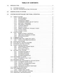
Руководство на английском языке по ремонту и техническому обслуживанию Dodge Ram 2004 года выпуска.
- Автор: —
- Издательство: DaimlerChrysler Corporation
- Год издания: —
- Страниц: 642
- Формат: PDF
- Размер: 1,5 Mb
Руководство на английском языке по ремонту и техническому обслуживанию Dodge Ram Truck 1500-2500-3500 2005 года выпуска.
- Автор: —
- Издательство: DaimlerChrysler Corporation
- Год издания: 2004
- Страниц: 8395
- Формат: PDF
- Размер: 128,0 Mb

Руководство на английском языке по ремонту и техническому обслуживанию Dodge Ram Truck 1500 2009 года выпуска.
- Автор: —
- Издательство: —
- Год издания: —
- Страниц: —
- Формат: HTML
- Размер: 157,7 Mb
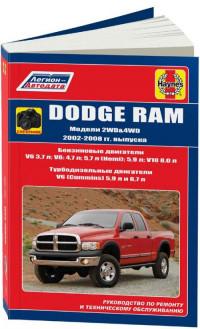
Руководство по техническому обслуживанию и ремонту автомобиля Dodge Ram 2002-2008 годов выпуска с бензиновыми и дизельными двигателями.
- Автор: —
- Издательство: Легион-Автодата
- Год издания: —
- Страниц: 306
- Формат: —
- Размер: —
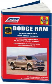
Руководство по техническому обслуживанию и ремонту автомобиля Dodge Ram 2009-2012 годов выпуска с бензиновыми и дизельными двигателями.
- Автор: —
- Издательство: Легион-Автодата
- Год издания: —
- Страниц: 294
- Формат: —
- Размер: —
