Инструкции и ПО для оборудования Javad
Javad Alpha Руководство по эксплуатации
Javad Alpha Технические характеристики
Javad Delta Руководство по эксплуатации
Javad Delta Технические характеристики
Javad Sigma Руководство по эксплуатации
Javad Sigma Технические характеристики
Javad Sigma-G2T Технические характеристики
Javad Sigma-G3T Технические характеристики

Javad Triumph-1 Руководство по эксплуатации
Javad Triumph-1 Быстрый старт
Javad Triumph-1 Технические характеристики
Javad Triumph-1-G3T Технические характеристики
Javad Triumph-1 RTK c GSM-модемом c помощью ПО Tracy
Javad Triumph-1M Руководство по эксплуатации
Javad Triumph-1M Технические характеристики
Javad Triumph-2 Руководство по эксплуатации
Javad Triumph-2 Технические характеристики
Javad Triumpn-LS Руководство пользователя
Javad Triumpn-LS Технические характеристики
Javad Triumph-VS Руководство по эксплуатации
Javad Triumph-VS Технические характеристики
Javad Justin Руководство по использованию ПО
Javad Justin Локализация (калибровка)
Javad Justin Обработка данных ГНСС
Javad Justin Уравнивание
Javad Justin Мониторинг положения спутникового приёмника (NMEA режим)
Javad GIODIS Руководство по использованию программного обеспечения
Deformation Analyzer Руководство по использованию программного обеспечения
Javad HPT104BT Руководство пользователя
Javad HPT135BT Руководство пользователя
Javad HPT135BT Технические характеристики
Javad HPT404BT Первое знакомство
Javad HPT404BT Технические характеристики
Javad HPT435BT Руководство пользователя
Javad HPT435BT Первое знакомство
Javad HPT435BT Технические характеристики
Javad Jlink 3G Технические характеристики
-
JustinSoftware Quick Reference Guide
Version 1.0Last Revised April 10, 2008
All contents in this manual are copyrighted by JAVAD GNSS.All
rights reserved.The information contained herein may not be used,
accessed, copied,stored, displayed, sold, modified, published, or distributed, or
otherwise reproduced without express written consent from JAVAD
GNSS. -
www.javad.com
-
3www.javad.com
TABLE OF CONTENTS
Preface . . . . . . . . . . . . . . . . . . . . . . . . . . . .
. . . . . . . . . . . . . . . . . . . . . . . . . . . . . . . . . .
7Terms and Conditions. . . . . . . . . . . . . . . . . . . . . . .
. . . . . . . . . . . . . . . . . . . . . . . . . . . . . . . . .
7About this Guide. . . . . . . . . . . . . . . . . . . . . . . . .
. . . . . . . . . . . . . . . . . . . . . . . . . . . . . . . . . .
. 9Symbols and Typographic Conventions . . . . . . . . . . . . . .
. . . . . . . . . . . . . . . . . . . . . . . . 9Screen Captures .
. . . . . . . . . . . . . . . . . . . . . . . . . . . . . . . . . .
. . . . . . . . . . . . . . . . . . . . . 9Technical Support. . . . . . . . . . . . . . . . . . . . . . . .
. . . . . . . . . . . . . . . . . . . . . . . . . . . . . . . . . .
. 9Chapter 1. Introduction. . . . . . . . . . . . . . . . . . . . .
. . . . . . . . . . . . . . . . . . . . . . . . . . . . 111.1.
System Requirements . . . . . . . . . . . . . . . . . . . . . . . .
. . . . . . . . . . . . . . . . . . . . . . . . . . . 11Chapter 2. Getting Started . . . . . . . . . . . . . . . . . . .
. . . . . . . . . . . . . . . . . . . . . . . . . . . 132.1.
Understanding Elements of the Main Window . . . . . . . . . . . . .
. . . . . . . . . . . . . . . . . . . 132.1.1. Menu and Tool Bar . . . . . . . . . . . . . . . . . . . .
. . . . . . . . . . . . . . . . . . . . . . . . . . . . 142.1.2.
Project and Map Panes . . . . . . . . . . . . . . . . . . . . . . .
. . . . . . . . . . . . . . . . . . . . . . 142.1.3. Status Bar . .
. . . . . . . . . . . . . . . . . . . . . . . . . . . . . . . . . .
. . . . . . . . . . . . . . . . . . . 152.2. Creating a New Project . . . . . . . . . . . . . . . . . .
. . . . . . . . . . . . . . . . . . . . . . . . . . . . . . . .
152.2.1. Defining General Properties . . . . . . . . . . . . . . .
. . . . . . . . . . . . . . . . . . . . . . . . . . 152.2.2.
Defining Scenario . . . . . . . . . . . . . . . . . . . . . . . . .
. . . . . . . . . . . . . . . . . . . . . . . . 162.2.3. Selecting
Coordinate Systems . . . . . . . . . . . . . . . . . . . . . . . .
. . . . . . . . . . . . . . . . 192.2.4. Setting the Coordinate
System for the Map Pane . . . . . . . . . . . . . . . . . . . . . .
. . . 202.2.5. Setting Geoid Models . . . . . . . . . . . . . . . .
. . . . . . . . . . . . . . . . . . . . . . . . . . . . . .
212.2.6. Loading Fiducial Points. . . . . . . . . . . . . . . . . .
. . . . . . . . . . . . . . . . . . . . . . . . . . . 222.2.7.
Including/Excluding Satellites . . . . . . . . . . . . . . . . . .
. . . . . . . . . . . . . . . . . . . . . 232.3. Creating a Fiducial Points Database . . . . . . . . . . . .
. . . . . . . . . . . . . . . . . . . . . . . . . . . . 252.3.1.
Adding Fiducial Point Coordinates . . . . . . . . . . . . . . . . .
. . . . . . . . . . . . . . . . . . . 252.3.2. Editing Fiducial
Point . . . . . . . . . . . . . . . . . . . . . . . . . . . . . . .
. . . . . . . . . . . . . . . 262.3.3. Deleting a Fiducial Point
from the Database. . . . . . . . . . . . . . . . . . . . . . . . .
. . . . 272.3.4. Deleting a Group of Fiducial Points from the
Database . . . . . . . . . . . . . . . . . . . . 272.3.5. Export
and Import Buttons . . . . . . . . . . . . . . . . . . . . . . . .
. . . . . . . . . . . . . . . . . . 272.4. Setting Application Options . . . . . . . . . . . . . . . .
. . . . . . . . . . . . . . . . . . . . . . . . . . . . . . 29 -
4 www.javad.com
2.5. Importing Files . . . . . . . . . . . . . . . . . . . . . .
. . . . . . . . . . . . . . . . . . . . . . . . . . . . . . . . . .
302.5.1. Importing a File . . . . . . . . . . . . . . . . . . . . .
. . . . . . . . . . . . . . . . . . . . . . . . . . . . . 312.5.2.
Importing a Folder with Raw Data. . . . . . . . . . . . . . . . . .
. . . . . . . . . . . . . . . . . . 322.5.3. Importing Data from a
Project . . . . . . . . . . . . . . . . . . . . . . . . . . . . . .
. . . . . . . . . 332.5.4. Importing SNAP Files . . . . . . . . . .
. . . . . . . . . . . . . . . . . . . . . . . . . . . . . . . . . .
. 332.5.5. Setting the Import Options . . . . . . . . . . . . . . .
. . . . . . . . . . . . . . . . . . . . . . . . . . . 34Chapter 3. Justin GIS Features. . . . . . . . . . . . . . . . .
. . . . . . . . . . . . . . . . . . . . . . . . . . 353.1. Using a
Toolbar and Map Menu. . . . . . . . . . . . . . . . . . . . . . . .
. . . . . . . . . . . . . . . . . . . 353.2. Using the Map Tab . . . . . . . . . . . . . . . . . . . . .
. . . . . . . . . . . . . . . . . . . . . . . . . . . . . . . .
363.3. Using the Map Pane . . . . . . . . . . . . . . . . . . . .
. . . . . . . . . . . . . . . . . . . . . . . . . . . . . . . .
37Chapter 4. Processing . . . . . . . . . . . . . . . . . . . . .
. . . . . . . . . . . . . . . . . . . . . . . . . . . . 394.1.
Processing in Automatic Mode. . . . . . . . . . . . . . . . . . . .
. . . . . . . . . . . . . . . . . . . . . . . . 394.2. Single Vector Processing in Manual Mode . . . . . . . . . .
. . . . . . . . . . . . . . . . . . . . . . . . 414.3. Group of Vectors Processing in Manual Mode . . . . . . . .
. . . . . . . . . . . . . . . . . . . . . . . 414.4. Single Vector Processing in Interactive Mode . . . . . . .
. . . . . . . . . . . . . . . . . . . . . . . . . 424.5. Saving Residuals. . . . . . . . . . . . . . . . . . . . . .
. . . . . . . . . . . . . . . . . . . . . . . . . . . . . . . . .
43Chapter 5. Adjustment . . . . . . . . . . . . . . . . . . . . .
. . . . . . . . . . . . . . . . . . . . . . . . . . . . 455.1.
Running Adjustment Automatically . . . . . . . . . . . . . . . . .
. . . . . . . . . . . . . . . . . . . . . . . 455.2. Running Adjustment Manually. . . . . . . . . . . . . . . .
. . . . . . . . . . . . . . . . . . . . . . . . . . . . 465.2.1.
Setting Adjustment Parameters . . . . . . . . . . . . . . . . . . .
. . . . . . . . . . . . . . . . . . . 46Chapter 6. Reports . . . . . . . . . . . . . . . . . . . . . . .
. . . . . . . . . . . . . . . . . . . . . . . . . . . . . 496.1.
Solution Reports . . . . . . . . . . . . . . . . . . . . . . . . .
. . . . . . . . . . . . . . . . . . . . . . . . . . . . . . 496.2. Vector Reports . . . . . . . . . . . . . . . . . . . . . .
. . . . . . . . . . . . . . . . . . . . . . . . . . . . . . . . . .
506.3. Adjustment Reports . . . . . . . . . . . . . . . . . . . .
. . . . . . . . . . . . . . . . . . . . . . . . . . . . . . . .
51 -
5www.javad.com
LIST OF FIGURES
Main window . . . . . . . . . . . . . . . . . . . . . . . . . .
. . . . . . . . . . . . . . . . . . . . . . . . . . . . . . .
13Menu bar . . . . . . . . . . . . . . . . . . . . . . . . . . . .
. . . . . . . . . . . . . . . . . . . . . . . . . . . . . . . . .
14Tool bar . . . . . . . . . . . . . . . . . . . . . . . . . . . .
. . . . . . . . . . . . . . . . . . . . . . . . . . . . . . . . .
14Project and Map panes . . . . . . . . . . . . . . . . . . . . . .
. . . . . . . . . . . . . . . . . . . . . . . . . . . . 14Project
properties. General tab . . . . . . . . . . . . . . . . . . . . . .
. . . . . . . . . . . . . . . . . . . . . . 15Scenario tab . . . .
. . . . . . . . . . . . . . . . . . . . . . . . . . . . . . . . . .
. . . . . . . . . . . . . . . . . . . . 16Truncate receiver time
check box . . . . . . . . . . . . . . . . . . . . . . . . . . . . .
. . . . . . . . . . . . 17Scenario tab settings . . . . . . . . . .
. . . . . . . . . . . . . . . . . . . . . . . . . . . . . . . . . .
. . . . . . . . 17Tolerance field settings . . . . . . . . . . . .
. . . . . . . . . . . . . . . . . . . . . . . . . . . . . . . . . .
. . . 17Auto-start field settings . . . . . . . . . . . . . . . . .
. . . . . . . . . . . . . . . . . . . . . . . . . . . . . . . .
18Reports form selecting . . . . . . . . . . . . . . . . . . . . .
. . . . . . . . . . . . . . . . . . . . . . . . . . . . . 18
Scenario drop-down list box . . . . . . . . . . . . . . . . . . . .
. . . . . . . . . . . . . . . . . . . . . . . . . 18Saved scenarios
. . . . . . . . . . . . . . . . . . . . . . . . . . . . . . . . . .
. . . . . . . . . . . . . . . . . . . . . 19Coordinate systems tab
. . . . . . . . . . . . . . . . . . . . . . . . . . . . . . . . . .
. . . . . . . . . . . . . . . . 20Map tab . . . . . . . . . . . . .
. . . . . . . . . . . . . . . . . . . . . . . . . . . . . . . . . .
. . . . . . . . . . . . . . . 21Geoid tab . . . . . . . . . . . . .
. . . . . . . . . . . . . . . . . . . . . . . . . . . . . . . . . .
. . . . . . . . . . . . . 22Fiducial points tab . . . . . . . . . .
. . . . . . . . . . . . . . . . . . . . . . . . . . . . . . . . . .
. . . . . . . . . 23Satellites tab . . . . . . . . . . . . . . . .
. . . . . . . . . . . . . . . . . . . . . . . . . . . . . . . . . .
. . . . . . . . 24Fiducial points dialog window . . . . . . . . . .
. . . . . . . . . . . . . . . . . . . . . . . . . . . . . . . . . .
25 Adding a new group . . . . . . . . . . . . . . . . . . . . . . .
. . . . . . . . . . . . . . . . . . . . . . . . . . . . 25Fiducial
point parameters . . . . . . . . . . . . . . . . . . . . . . . . .
. . . . . . . . . . . . . . . . . . . . . . . 26Delete group . . .
. . . . . . . . . . . . . . . . . . . . . . . . . . . . . . . . . .
. . . . . . . . . . . . . . . . . . . . . 27Reference points dialog
window . . . . . . . . . . . . . . . . . . . . . . . . . . . . . .
. . . . . . . . . . . . 28Common tab . . . . . . . . . . . . . . .
. . . . . . . . . . . . . . . . . . . . . . . . . . . . . . . . . .
. . . . . . . . . 29Import files dialog window . . . . . . . . . .
. . . . . . . . . . . . . . . . . . . . . . . . . . . . . . . . . .
. . 31Import Progress window . . . . . . . . . . . . . . . . . . .
. . . . . . . . . . . . . . . . . . . . . . . . . . . . . 32 Import
SNAP files . . . . . . . . . . . . . . . . . . . . . . . . . . . .
. . . . . . . . . . . . . . . . . . . . . . . . . 33Options dialog
window. Import tab . . . . . . . . . . . . . . . . . . . . . . . .
. . . . . . . . . . . . . . . . 34Import Options . . . . . . . . .
. . . . . . . . . . . . . . . . . . . . . . . . . . . . . . . . . .
. . . . . . . . . . . . . 34Edit layer pop-up menu . . . . . . . .
. . . . . . . . . . . . . . . . . . . . . . . . . . . . . . . . . .
. . . . . . . 37 -
6 www.javad.com
Site (on the left) and solution (on the right) pop-up menus . .
. . . . . . . . . . . . . . . . . . . 38Batch process window . . .
. . . . . . . . . . . . . . . . . . . . . . . . . . . . . . . . . .
. . . . . . . . . . . . . 39 Project pane. Process tab . . . . . .
. . . . . . . . . . . . . . . . . . . . . . . . . . . . . . . . . .
. . . . . . . 40Vector pop-up menu . . . . . . . . . . . . . . . .
. . . . . . . . . . . . . . . . . . . . . . . . . . . . . . . . . .
. 41 Vector pop-up menu . . . . . . . . . . . . . . . . . . . . . .
. . . . . . . . . . . . . . . . . . . . . . . . . . . . . 42 Run
time settings Window . . . . . . . . . . . . . . . . . . . . . . .
. . . . . . . . . . . . . . . . . . . . . . . 42Vector node pop-up
menu . . . . . . . . . . . . . . . . . . . . . . . . . . . . . . .
. . . . . . . . . . . . . . . . 43Vector pop-up menu . . . . . . .
. . . . . . . . . . . . . . . . . . . . . . . . . . . . . . . . . .
. . . . . . . . . . 44 Network pop-up menu . . . . . . . . . . . .
. . . . . . . . . . . . . . . . . . . . . . . . . . . . . . . . . .
. . . 46Adjustment parameters dialog window . . . . . . . . . . . .
. . . . . . . . . . . . . . . . . . . . . . . . . 47 Creating a
solution report . . . . . . . . . . . . . . . . . . . . . . . . . .
. . . . . . . . . . . . . . . . . . . . . 49Creating a vector
report . . . . . . . . . . . . . . . . . . . . . . . . . . . . . .
. . . . . . . . . . . . . . . . . . . 50Report dialog window.
Static button . . . . . . . . . . . . . . . . . . . . . . . . . . .
. . . . . . . . . . . . 50 Creating an adjustment report . . . . .
. . . . . . . . . . . . . . . . . . . . . . . . . . . . . . . . . .
. . . . 51Report dialog window. Network button . . . . . . . . . .
. . . . . . . . . . . . . . . . . . . . . . . . . . 51 -
7www.javad.com
PREFACE
Thank you for purchasing this JAVAD GNSS product. The materials
available in this SoftwareQuick Reference Guide (the Guide) have
been prepared by JAVAD GNSS for owners of JAVADGNSS products. It is
designed to assist owners with the operating of the Justin Software
and itsuse is subject to these terms and conditions (the Terms and
Conditions).Note: Please read these Terms and Conditions carefully.
Terms and ConditionsUSE JAVAD GNSS products are designed to be
used by a professional. The user is expected tohave a good
knowledge and understanding of the user and safety instructions
before operating,inspecting or adjusting. Always wear the required
protectors (safety shoes, helmet, etc.) whenoperating the
receiver.COPYRIGHT All information contained in this Guide is the
intellectual property of, andcopyrighted material of JAVAD GNSS.
All rights are reserved. You may not use, access, copy,store,
display, create derivative works of, sell, modify, publish,
distribute, or allow any third partyaccess to, any graphics,
content, information or data in this Guide without JAVAD GNSS
expresswritten consent and may only use such information for the
operation of your software. Theinformation and data in this Guide
are a valuable asset of JAVAD GNSS and are developed by
theexpenditure of considerable work, time and money, and are the
result of original selection,coordination and arrangement by JAVAD
GNSS.TRADEMARKS Justin, JAVAD GNSS are trademarks or registered
trademarks of JAVADGNSS. Windows is a registered trademark of
Microsoft Corporation, Bluetooth word mark isowned by the Bluetooth
SIG, Inc. Product and company names mentioned herein may
betrademarks of their respective owners.DISCLAIMER OF WARRANTY EXCEPT FOR ANY WARRANTIES IN THIS GUIDE
ORA WARRANTY CARD ACCOMPANYING THE PRODUCT, THIS GUIDE AND
SOFTWAREARE PROVIDED AS-IS. THERE ARE NO OTHER WARRANTIES. JAVAD
GNSSDISCLAIMS ANY IMPLIED WARRANTY OF MERCHANTABILITY OR FITNESS
FORANY PARTICULAR USE OR PURPOSE. JAVAD GNSS AND ITS DISTRIBUTORS
SHALLNOT BE LIABLE FOR TECHNICAL OR EDITORIAL ERRORS OR
OMISSIONS -
PrefaceTerms and Conditions
8 www.javad.com
CONTAINED HEREIN; NOR FOR INCIDENTAL OR CONSEQUENTIAL
DAMAGESRESULTING FROM THE FURNISHING, PERFORMANCE OR USE OF THIS
MATERIAL.SUCH DISCLAIMED DAMAGES INCLUDE BUT ARE NOT LIMITED TO
LOSS OF TIME,LOSS OR DESTRUCTION OF DATA, LOSS OF PROFIT, SAVINGS
OR REVENUE, ORLOSS OF THE PRODUCT’S USE. IN ADDITION, JAVAD GNSS IS
NOT RESPONSIBLE ORLIABLE FOR DAMAGES OR COSTS INCURRED IN
CONNECTION WITH OBTAININGSUBSTITUTE PRODUCTS OR SOFTWARE, CLAIMS BY
OTHERS, INCONVENIENCE, ORANY OTHER COSTS. IN ANY EVENT, JAVAD GNSS
SHALL HAVE NO LIABILITY FORDAMAGES OR OTHERWISE TO YOU OR ANY OTHER
PERSON OR ENTITY IN EXCESSOF THE PURCHASE PRICE FOR THE TRACY
SOFTWARE.LICENSE AGREEMENT Use of any computer programs or software
supplied by JAVADGNSS or downloaded from a JAVAD GNSS website (the
Software) in connection with theJAVAD GNSS receivers constitutes
acceptance of these Terms and Conditions in this Guide andan
agreement to abide by these Terms and Conditions. The user is
granted a personal, non-exclusive, non-transferable license to use
such Software under the terms stated herein and in anycase only
with a single computer. You may not assign or transfer the Software
or this licensewithout the express written consent of JAVAD GNSS.
This license is effective until terminated.You may terminate the
license at any time by destroying the Software and Guide. JAVAD
GNSSmay terminate the license if you fail to comply with any of the
Terms or Conditions. You agree todestroy the Software and guide
upon termination of your use of software. All ownership,copyright
and other intellectual property rights in and to the Software
belong to JAVAD GNSS. Ifthese license terms are not acceptable,
return any unused software and guide.CONFIDENTIALITY This Guide, its contents and the Software
(collectively, the ConfidentialInformation) are the confidential
and proprietary information of JAVAD GNSS. You agree totreat JAVAD
GNSS’ Confidential Information with a degree of care no less
stringent that thedegree of care you would use in safeguarding your
own most valuable trade secrets. Nothing inthis paragraph shall
restrict you from disclosing Confidential Information to your
employees asmay be necessary or appropriate to operate Justin
Software. Such employees must also keep theConfidentiality
Information confidential. In the event you become legally compelled
to discloseany of the Confidential Information, you shall give
JAVAD GNSS immediate notice so that it mayseek a protective order
or other appropriate remedy.WEBSITE; OTHER STATEMENTS No statement contained at the JAVAD
GNSS website (orany other website) or in any other advertisements
or JAVAD GNSS literature or made by anemployee or independent
contractor of JAVAD GNSS modifies these Terms and
Conditions(including the Software license, warranty and limitation
of liability).MISCELLANEOUS The above Terms and Conditions may be amended,
modified, superseded,or canceled, at any time by JAVAD GNSS. The
above Terms and Conditions will be governed by, -
PrefaceAbout this Guide
Symbols and Typographic Conventions
9www.javad.com
and construed in accordance with, the laws of the State of
California, without reference to conflictof laws.About this Guide
Symbols and Typographic Conventions
This Guide uses the following text conventions:
Example Description.Port Titles of dialog windows/boxes, names
of menu options.Screen Captures
This Guide includes sample screen captures. Your actual screen
can look slightly different fromthe sample screen due to the
receiver you have connected, operating system used and settings
youhave specified. This is normal and not a cause for concern.Technical SupportOccasionally, Justin users encounter problems
during installation or use of the program. Shouldyou have any
problems with Justin Software, please contact JAVAD GNSS
Support([email protected]). -
PrefaceTechnical SupportScreen Captures
10 www.javad.com
-
Chapter 1
11www.javad.com
INTRODUCTION
The quick reference guide is designed to provide the quickest
way to get started using Justin.The guide is organized as follows:
Creating a project and importing data
Viewing, editing and processing data using the Project and Map
window.Adjusting a network.
Creating reports.
1.1. System Requirements
Before installing and running Justin, be sure that, your
computer satisfies the followingrequirements:PC-compatible computer
Processor: Pentium IV or higher
Installed Open GL drivers
2 GB available hard drive space
512 MB of RAM (minimum) or 1024 MB (recommended)
Microsoft Windows XP, Vista
-
IntroductionSystem Requirements
12 www.javad.com
-
Chapter 2
13www.javad.com
GETTING STARTED
This chapter describes how to create a project, create the
Fiducial Points Database, and importraw data files into a
project.2.1. Understanding Elements of the Main Window
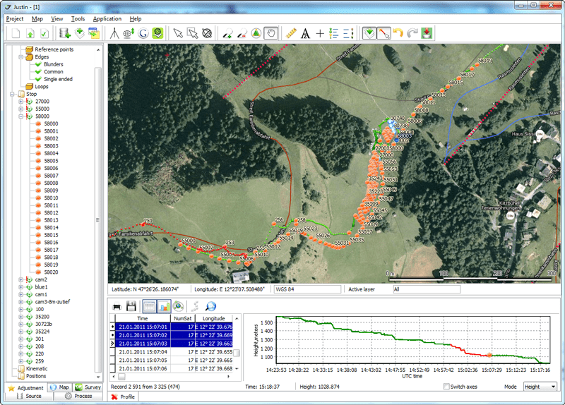
When you start Justin the Main window appears (Figure 2-1). This
window includes the followingcomponents: the Menu and Tool bar, the
Project and Map panes, which are the largest parts of thewindow,
and the Status bar.Figure 2-1. Main window
Menu barTool bar
Project pane
Map pane
Status bar
-
Getting StartedUnderstanding Elements of the Main WindowMenu and
Tool Bar14 www.javad.com
2.1.1. Menu and Tool Bar
The Menu bar (Figure 2-2) extends across the top of the Main
window and contains six menutitles through which the user can
access the program functions. By hovering the mouse pointerover a
menu title and then clicking the left mouse button will cause the
menu to drop down,displaying a list of menu items. Position your
pointing device on the desired menu item, then clickand release the
left mouse button and that function is invoked.Figure 2-2. Menu bar
The Tool bar (Figure 2-3) consists of many buttons, through
which the user can access theprogram functions.Figure 2-3. Tool bar
2.1.2. Project and Map Panes
The Project and Map panes are depicted in Figure 2-4. The
Project pane (on the left) is designedto display data structure.
The Map pane (on the right) is a cartographic window.Figure 2-4. Project and Map panes
-
Getting StartedCreating a New Project
Status Bar
15www.javad.com
2.1.3. Status Bar
The Status bar provides auxiliary information while using
Justin.2.2. Creating a New Project
If you run Justin for the first time the Project and Map panes
will be empty. In this case, youshould create a new project. To
create a new project it is necessary to define the projects
name,scenario, and other settings in the Project properties dialog
window. The sections below areorganized according to tabs of the
dialog window.2.2.1. Defining General Properties
To define a project name and location follow the next steps:
1. Click New on the Project menu or on the Tool bar. A Project
Properties dialog appears(Figure 2-5).Figure 2-5. Project properties. General tab
2. Enter the project name in the Name field.
-
Getting StartedCreating a New ProjectDefining Scenario
16 www.javad.com
3. Enter the location for the project in the Full path field or
click to navigate to thelocation where the project will be stored.
Justin creates a file with the .jpr file extension.4. Enter creator’s name and comment in the Creator and Comment
field respectively, ifneeded.Note: The Name and Full path fields are mandatory to fill
in.5. Click OK to save changes and close the dialog window.
2.2.2. Defining Scenario
Importing data files into the project generates some recordsets
according to Scenario. You shouldset up Scenario before importing
data files.1. Select Properties from the Project menu item or click button
. The Project propertiesdialog window appears.2. Click the Scenario tab (Figure 2-6).
Figure 2-6. Scenario tab
3. Select the Truncate receiver time check box to truncate the
receiver time and reduce thecorresponding raw data measurements to
the nearest whole epoch. -
Getting StartedCreating a New Project
Defining Scenario
17www.javad.com
Note: This procedure is normally applied to Trimbles raw data
files where reference times are wholeepochs originally given in
float (not whole epochs).Figure 2-7. Truncate receiver time check box
4. Enter the number of epochs in the Min recordset size field
(Figure 2-8). If the recordsethas epochs less than the Min
recordset size, the recordset is not included in the project.Figure 2-8. Scenario tab settings
5. Enter the maximum number of epochs in the Max epochs gap
field (Figure 2-8). If themax epoch gap exceeds the set value, a
recordset will be splitted.6. Enter a value in the Criterion for static field, to separate
Static and Kinematic recordsetsby navigational solution (Figure
2-8).7. Enter a value of the Cut off mask. It determines the lower
limit of the satellite elevation tobe used for navigational
solution. By default, it is 15 (Figure 2-8).8. Enter the value of Tolerance for static (Figure 2-9). This
criterion is used to set relationbetween recordsets and sites. If a
distance from navigational solution to an existing siteexceeds the
criterion*RMS, a new site is created.Figure 2-9. Tolerance field settings
-
Getting StartedCreating a New ProjectDefining Scenario
18 www.javad.com
9. Select the Processing check box (Figure 2-10). The vector
processing will startautomatically after data import.Figure 2-10. Auto-start field settings
10. Select the Adjustment check box. The program starts the
network adjustmentautomatically.11. In the Reports box select one or more check boxes of the
report forms to obtain thecorresponding report. Justin creates the
report .txt file automatically.Figure 2-11. Reports form selecting
Note: Click the Default button, to retain default settings.
It is possible to save scenario settings for using them in
another created new project. Follow thenext steps to save new
scenario:1. Click to enter the scenario name (Figure 2-12):
Figure 2-12. Scenario drop-down list box
-
Getting StartedCreating a New Project
Selecting Coordinate Systems
19www.javad.com
2. In the New scenario dialog window type the scenario name and
click OK. The scenariowill be added to the list. It is possible to
apply to the current project one of the savedscenarios selecting it
from the Scenario drop-down list box (Figure 2-13):Figure 2-13. Saved scenarios
3. To save changes click OK.
2.2.3. Selecting Coordinate Systems
It is possible to select the coordinate systems in Justin
database to copy it in the current project. Toselect a coordinate
system follow the next steps:1. Select Properties item from the Project menu or click button
. The Project propertiesdialog window appears. -
Getting StartedCreating a New ProjectSetting the Coordinate
System for the Map Pane20 www.javad.com
2. Click the Coordinate systems tab in the Project properties
dialog window (Figure 2-14):Figure 2-14. Coordinate systems tab
3. Click to open the list of available coordinate systems.
4. Select the coordinate system you want to use in project.
Note: WGS-84, Non-Earth, Oblique Stereographic systems are set
by default.5. Click OK to save changes and close the dialog window.
2.2.4. Setting the Coordinate System for the Map Pane
It is possible to set the coordinate system for the Map pane and
display it in the status bar. To setthe coordinate system follow
the next steps:1. Select Properties item from the Project menu or click button
. The Project propertiesdialog window appears. -
Getting StartedCreating a New Project
Setting Geoid Models
21www.javad.com
2. Click the Map tab (Figure 2-15).
Figure 2-15. Map tab
3. In the Coordinate system category highlight the desired
category of a coordinate system.4. In the Coordinate system highlight the desired coordinate
system.5. Click OK to save changes and close the dialog window.
2.2.5. Setting Geoid Models
Justin operates with global and local geoid models. It is
possible to set the geoid model for theproject in the Geoid list
and import new geoid models.Note: The EGM96 (Earth Geoid Model) is set by default.
To set the geoid model follow the next steps:
1. Select Properties item from the Project menu or click button
. The Project propertiesdialog window appears. -
Getting StartedCreating a New ProjectLoading Fiducial Points
22 www.javad.com
2. Click the Geoid tab (Figure 2-16).
Figure 2-16. Geoid tab
3. Highlight the necessary geoid model from the list.
4. If there is no necessary geoid in the list, click the Import
button. In the Open dialogwindow navigate to the geoid model file
location and click Open. The new model will beadded to the
list.5. Click OK to save changes and close the dialog window.
2.2.6. Loading Fiducial Points
Justin allows creating a Fiducial Points Database in interactive
mode. See Creating a FiducialPoints Database on page 25 for
detailed information.To load fiducial points from the database to the project follow
the next steps:1. Select Properties item from the Project menu or click button
. The Project propertiesdialog window appears. -
Getting StartedCreating a New Project
Including/Excluding Satellites
23www.javad.com
2. Click the Fiducial points tab (Figure 2-17).
Figure 2-17. Fiducial points tab
3. From the Available list, select a group/point you want to
copy to the project.4. Click or drag and drop the selected group/point into the
Project list. The group/pointappears in the Project list.5. Click OK to save changes and close the window.
2.2.7. Including/Excluding Satellites
Justin allows excluding satellites from computations. The green
and red buttons designate enabledand disabled satellites
respectively (Figure 2-18).1. Select Properties item from the Project menu or click button
. The Project propertiesdialog window appears.2. Click the Satellites tab. It displays used in the project
satellites. -
Getting StartedCreating a New ProjectIncluding/Excluding
Satellites24 www.javad.com
3. Click a green/red satellite button to exclude/include the
satellite.Figure 2-18. Satellites tab
4. Click OK to save changes and close the window.
-
Getting StartedCreating a Fiducial Points Database
Adding Fiducial Point Coordinates
25www.javad.com
2.3. Creating a Fiducial Points Database
Create a Fiducial Points database before using fiducial points
in your project. Justin allows addingfiducial points to the Justin
database and edit them. The Fiducial Points database is available
forany Justin projects.2.3.1. Adding Fiducial Point Coordinates
To add a fiducial point into the Database follow the next
steps:1. Click on the Toolbar. The Fiducial Points dialog window
opens.Figure 2-19. Fiducial points dialog window
2. To add a new group right-click the Fiducial points node and
click Add group.Figure 2-20. Adding a new group
3. The Add group dialog windows opens allowing the user to enter
a new group name. -
Getting StartedCreating a Fiducial Points DatabaseEditing
Fiducial Point26 www.javad.com
4. Click OK. The new group appears as a sub-node.
5. Select the group you want the point will be stored.
6. Click Edit point button.
7. Enter a point name in the Point name field (Figure 2-21).
Figure 2-21. Fiducial point parameters
8. Enter the point coordinates.
9. Select the desired coordinate system.
10. Click Add point button, the new point appears at the
appropriate level.11. Repeat the steps 5-10 for each point you want to add to the
database.12. Click OK to apply changes to the database and close the
dialog window.2.3.2. Editing Fiducial Point
To edit a point’s name, coordinates, and Sigmas follow the next
steps:1. Click . The Fiducial Points dialog window opens.
2. Select the point you want to edit.
3. Press Edit point button.
4. Type the new name, coordinates and Sigmas.
5. Press Apply changes button to set and save the changes to the
current point.6. Press Cancel button to exit the edit mode.
-
Getting StartedCreating a Fiducial Points Database
Deleting a Fiducial Point from the Database
27www.javad.com
2.3.3. Deleting a Fiducial Point from the Database
To delete the point from the database:
1. Click . The Fiducial Points dialog window opens.
2. Select the desired point.
3. Click the Delete button.
4. Click OK to apply changes and close the dialog window. Or
click Cancel to close thedialog window without saving changes.2.3.4. Deleting a Group of Fiducial Points from the Database
To delete a group of points from the database:
1. Click . The Fiducial Points dialog window opens.
2. Right-click the desired group.
3. Select Delete group in the pop-up menu.
Figure 2-22. Delete group
4. Click OK to apply changes and close the dialog window. Or
click Cancel to close thedialog window without saving changes.2.3.5. Export and Import Buttons
It is recommended to use the Export/Import buttons when it is
necessary to transfer the fiducialpoints database from one PC to
another.To export fiducial points from the current project to a .jst
file follow the next steps:1. Click to open the Fiducial Points dialog window (see Figure
2-19 on page 25). -
Getting StartedCreating a Fiducial Points DatabaseExport and
Import Buttons28 www.javad.com
2. Press the Export button. A Reference points dialog window
opens.Figure 2-23. Reference points dialog window
3. Select the desired group/point check box to insert the points
into a .jst file.4. Click OK. The Save as dialog window opens.
Enter a file name and location.5. Click OK.
To import the .jst file to the project,
1. Click on the Toolbar to open the Fiducial Points dialog
window.2. Click the Import button.
3. In the Open dialog window navigate to the .jst file you want
to import.4. Click OK to add the fiducial points to the
database. -
Getting StartedSetting Application OptionsExport and Import
Buttons29www.javad.com
2.4. Setting Application Options
Justin Application Options are intended to provide two main
tasks:Supporting Windows regional and language settings.
Customizing Justin environment.
It is possible to change Justins options according user personal
preferences. Use the Optionsdialog window to set up the custom
options. These settings will be system defaults for everyproject
until you change them.To change options follow the next steps:
1. Select the Application item from the Options menu. The
Options dialog window appears.2. Click the Common Tab.
Figure 2-24. Common tab
3. In the Language drop-down list box select the language.
English is set by default.4. Enable the following options:
Open last project to open the last saved project when
starting.Compact project database on exit to compact the project database
when exit. It might beuseful in some cases to save disk space and
optimize a project.Decimal degrees in coordinates form to display coordinates in
the decimal degrees format.Show scale bar to show a scale bar on a map.
Longitude range specifies the range of displaying longitude. It
may be either from -180 to180 or from 0 to 360 degrees.Button panel in object tree to open the button panel in the
Project pane. -
Getting StartedImporting FilesExport and Import Buttons
30 www.javad.com
5. Click OK to save the changes and close the window.
2.5. Importing Files
Justin allows importing raw data files from a PC hard disk to a
project. It can be implemented inone of the following ways:Importing a file or multiple files;
Importing the whole folder;
Importing the data from an existing project.
Justin allows importing the following file formats:
JPS, TPS binary files
RINEX files
SP3 files
Ashtech O- and SNAP-files
Note: The successfully imported raw data files are saved in the
project and might be deleted from PCshard disc after importing. -
Getting StartedImporting Files
Importing a File
31www.javad.com
2.5.1. Importing a File
To import a file to the project follow the next steps:
1. Click Import files item from the Project menu or on the
Toolbar. The Import filesdialog window appears (Figure 2-25):Figure 2-25. Import files dialog window
2. Select the type of file you want to import in the Files of
type drop-down list.3. Navigate to and select the desired file.
Note: To select multiple sequential files, press Shift and then
use the Up and Down keys. To selectnonsequential files press Ctrl
and click the desired files.4. Click Open to import the file to the current project.
5. In the Import progress window it will be shown the import
progress, the name of the filebeing imported, and messages. It is
possible to save the import status information into afile. See
Setting the Import Options on page 34 for detailed information
about this andother useful options. -
Getting StartedImporting FilesImporting a Folder with Raw
Data32 www.javad.com
To stop the import process click Cancel (Figure 2-26).
Figure 2-26. Import Progress window
6. If the import is successfully completed, the imported data
will be shown in the Source tabof the Project pane and on the Map
pane.Note: Click the Import log item from the Project menu to open
the ImportLog.txt file and see adetailed report about data
import.2.5.2. Importing a Folder with Raw Data
To import a folder to the project, follow the next steps:
1. Click Import folder item from the Project menu. The Select
path dialog window.2. Select the desired folder and click OK. It opens a window
with the information about theimport progress, the currently
imported file, and errors.Note: It is possible to import the .**O, .**G, .**N, and .jps
files in the folder.Note: If there are sub-folders in the imported folder, Justin
runs through the sub-folders and extracts therequired files to the
project. During the importing data, Receiver IDs and time spans are
testeddue to avoid data duplication.3. If the import is successfully completed, the imported data
will be shown in the Source tabof the Project pane and on the Map
pane. -
Getting StartedImporting Files
Importing Data from a Project
33www.javad.com
2.5.3. Importing Data from a Project
To import data from a previously created project follow the next
steps:1. Click Import from project item from the Project menu. The
Open project dialog windowappears.2. Select the desired file from the list.
3. Click OK.
2.5.4. Importing SNAP Files
To import SNAP files follow the next steps:
1. Click the Source tab in the Project pane.
2. Right-click the project name. In the pop-up menu (Figure
2-27) select Import SNAP files.Figure 2-27. Import SNAP files
3. The Select path dialog window appears.
Note: This dialog window allows selecting a folder with a couple
of SNAP files (station.dat andvector.dat).4. Navigate to the desired folder and click OK.
-
Getting StartedImporting FilesSetting the Import Options
34 www.javad.com
2.5.5. Setting the Import Options
Use the Options dialog window to customize the Import progress
window information:1. Click the Application item from the Options menu.
2. Click the Import tab.
Figure 2-28. Options dialog window. Import tab
3. Enable the following options:
Figure 2-29. Import Options
Raise error on unknown tag to display messages if any errors
occur during importing afile.Interrupt on error to stop the import process if an error
occurs.Error message logging to log the ImportLog.txt file.
4. Click OK to apply the changes.
-
Chapter 3
35www.javad.com
JUSTIN GIS FEATURES
This chapter describes how to manage the processed data using
the Justin Map options andcontrols, and the basics of specific
Justin GIS features.3.1. Using a Toolbar and Map Menu
We recommend that you do not accomplishing any task on a map
before you familiarize yourselfwith the operating elements and the
map environment.Some map menu items are duplicated in the tool bar. The
following table summarizes theinformation on using the Justin
toolbar and menu items.Buttons The Map Menu Purpose
Add layer Add a layer to a map.
Run Google Earth to display a network scheme on a map.
Save Save a map as a geoset.
Show entire network
Display an entire network in the Map pane
Select a point on a map.
Zoom in Zoom in the map image.
Zoom out Zoom out the map image.
Move Change the cursor to a hand and allows moving the map
views.Distance Change the cursor to a crosshair and allows measuring a
distance between two points. The distance displays in the Status
bar.Get coordinates from a map (it is used for georeferencing).
-
Justin GIS FeaturesUsing the Map Tab
36 www.javad.com
3.2. Using the Map Tab
Note: It is supposed that a project is open and the Map pane
displays imported data files.Justin allows performing the tasks on a map using the Map pane
and the Map tab of the Projectpane. The available actions are
listed below. Detailed instructions are included under each
bullet.Make a layer invisible.
Note: By default all layers are visible.
To hide a layer on the map, follow the next steps:
1. Click the Map tab in the Project pain.
2. Double-click the check box next to the layer, to clear the
check box. The layer becomesinvisible on the map.Make one layer visible. (Hide all the others.)
If you want to display one layer on the map and hide the
others:1. Click the Map tab in the Project pain.
2. Place the mouse cursor over the layer you want to display and
click the right-mousebutton.3. In the pop-up menu select Hide all layers except…
Change layer properties.
To change layer properties, follow the next steps:
1. Click the Map tab in the Project pain.
2. Place the mouse cursor over the layer and click the
right-mouse button.3. Select the desired option from the pop-up menu.
Open an additional pane on the left to display a map in a big
scale.Make program layers accessible. It gives a result, if the button
is pressed.Previous map view.
Next map view.
Buttons The Map Menu Purpose
-
Justin GIS FeaturesUsing the Map Pane
37www.javad.com
3.3. Using the Map Pane
It is possible to perform some tasks in the Map pane. The
available actions are listed below.Detailed instructions are
included under each bullet.Note: It is supposed that a project is open and the Map pane is
not empty.Zoom in and zoom out by using the mouse wheel.
Run Google Earth and display the project on a map.
1. Make sure that Google Earth Version 4.0 or more is installed
on your computer.2. Click on the Toolbar. Justin runs Google Earth and displays
the project location on theglobe.Note: If Google Earth displays a message and prompts you to
update the version of Google Earth.Update it and click once
more.Make a layer active.
To make a layer active, do the following steps:
1. Go to the Status bar.
2. Right-click within the Edit layer field.
3. Click the desired radio button in the pop-up menu (Figure
3-1). This layer becomesaccessible on the map.Figure 3-1. Edit layer pop-up menu
Select an object.
To select an object, do the following steps:
-
Justin GIS FeaturesUsing the Map Pane
38 www.javad.com
1. Click on the Tool bar. The mouse cursor changes to an arrow
with which to select an object.2. Place the arrow over the object and left-click the mouse
button.Use an object’s pop-up menu.
To open the objects pop-up menu, follow the next steps:
1. Select a desired object on the map.
2. Right-click the object.
3. Use the pop-up menu to accomplish your task.
Note: The options displayed on the pop-up menu vary depending on
what you have selected. You willsee different menus when you
right-click on a vector or a site. See the Figure 3-2 for
example.Figure 3-2. Site (on the left) and solution (on the right)
pop-up menus -
Chapter 4
39www.javad.com
PROCESSING
4.1. Processing in Automatic Mode
Processing starts automatically after finishing the data files
import. This option is set by default inthe Project properties
dialog window (see on page 18 how to set the automatic
process).When the file import is completed successfully (see Importing
Files on page 30 how to importthe raw data files), the Batch
process window appears (Figure 4-1):Figure 4-1. Batch process window
To stop the files processing, click Cancel.
-
ProcessingProcessing in Automatic Mode
40 www.javad.com
When the Batch process window closes, click the Process tab of
the Project pane, to see thecomputed vectors tree. It looks like
this (Figure 4-2):Figure 4-2. Project pane. Process tab
The vectors tree has the following structure:
The first node is the data of raw data files creation;
The second is the beginning point node (or base for kinematic).
The beginning point nodeis expanded to show an end point node (or
rover). If the vector has been processed, the endpoint node expands
to reveal a solution.To expand a level, double-click next to desired level.
-
ProcessingSingle Vector Processing in Manual Mode
41www.javad.com
4.2. Single Vector Processing in Manual Mode
To process single vector in manual mode, follow the next
steps:1. Click the Process tab of the Project pane. Right-click the
desired vector in the Projectpane. Or right-click the desired
vector on the Map pane. The pop-up menu opens(Figure 4-3):Figure 4-3. Vector pop-up menu
2. Select Process. The Processing progress bar appears.
3. In the Project pane, the button appears next to the processed
vector. Click the button,to view the solution. In the Map pane, a
new object appears in the Solution layer.Note: You can define a solution displaying style in the Map
pane. Use Style item from the solutionspop-up menu to set a line
color.4.3. Group of Vectors Processing in Manual Mode
If it is necessary to process more, than one vector follow the
next steps:1. Right-click one of the following nodes:
The Vectors node (Project pane, Process tab) to process all
vectors contained in the currentproject.The Data node (under the Vectors node) to process vectors
measured on this date.The Beginning point node to process vectors relating to the
beginning point.2. In the pop-up menu click Process all. The Batch process
window appears. -
ProcessingSingle Vector Processing in Interactive Mode
42 www.javad.com
4.4. Single Vector Processing in Interactive Mode
To process single vector in interactive mode, follow the next
steps:1. Right-click the desired vector in the Project pane. Or
right-click the desired vector on theMap pane. The pop-up menu
appears (Figure 4-4).Figure 4-4. Vector pop-up menu
2. From the pop-up menu, select Run time settings it opens a new
pane allowing the user tochange the settings.Figure 4-5. Run time settings Window
-
ProcessingSaving Residuals
43www.javad.com
1. Change the settings as you need. Use the Shift and Ctrl keys
to limit time intervals.2. To run Process, click .4.5. Saving Residuals
Note: Process yields residuals as a result of subtraction
observed and calculated double differencedcarrier phase values.Justin allows saving residuals using:
Process properties dialog window.
Run time setting window.
To save residuals using Process properties dialog window, follow
the next steps:1. Click the Process tab of the Project pane.
2. Right-click the Vector node.
3. On the pop-up menu click Process properties (Figure 4-6).
Figure 4-6. Vector node pop-up menu
4. On the Process properties dialog window select the Save
residuals check box.5. Click OK.
To save residuals using the Run time setting window, follow the
next steps:1. Select an unprocessed vector in the Project pane or Map
pane. -
ProcessingSaving Residuals
44 www.javad.com
2. Right-click the selected vector, to open the pop-up menu
(Figure 4-7).Figure 4-7. Vector pop-up menu
3. Select Run time settings. It opens the Run time settings
window.4. Select the Save residuals check box.
5. Click .
-
Chapter 5
45www.javad.com
ADJUSTMENT
5.1. Running Adjustment Automatically
This method works when a project is open, but data files are not
imported yet. In this case, do thefollowing steps:1. Select Properties item from the Project menu or click on the
toolbar. The Projectproperties dialog window opens.2. Open the Fiducial points tab to copy the desired fiducial
points from the Justin database tothe project. It allows snapping
sites to the fiducial points.3. Select the Scenario tab.
4. Select the Processing and Adjustment check boxes.
5. Click OK. Justin implements the adjustment automatically when
the file import has beencompleted successfully.6. Select the Adjustment tab of the Project pane to check the
adjustment process is over.Justin uses the following adjustment parameters by default (see
Setting Adjustment Parametersfor detailed information about
adjustment parameters):Mode: XYZ
Blunders: Automatic
Tau test
Transformation: None
Constraints: Fixed constraints.
-
AdjustmentRunning Adjustment ManuallySetting Adjustment
Parameters46 www.javad.com
5.2. Running Adjustment Manually
To adjust the network follow the next steps:
1. Open the Adjustment tab of the Project pane.
2. Right-click the Network node. The pop-up menu appears.
Figure 5-1. Network pop-up menu
3. Select Adjustment parameters, to change the adjustment
parameters.4. Select Adjust, to run the adjustment process.
5.2.1. Setting Adjustment Parameters
To set up the desired adjustment parameters follow the next
steps:1. Open the Adjustment tab of the Project pane.
2. Right-click the Network node.
-
AdjustmentRunning Adjustment Manually
Setting Adjustment Parameters
47www.javad.com
3. In the pop-up menu select Adjustment parameters. The
Adjustment Parameters dialogwindow appears (Figure 5-1).Figure 5-2. Adjustment parameters dialog window
4. Select the desired parameters as explained below:
In the Mode group select a coordinate system (either NEU or XYZ)
in which Justin willadjust.Note: To separate vertical errors select the NEU radio button.
To mark blunders on the Map pane select2D/3D.In the Blunders group select either Automatic or Interactive.
Automatic is set by default.Select a confidence level (either 95% or 99%) for the
Chi-squares and the blunderdetection tests.Note: If the 95% confidence level is selected the more strict
condition for rejecting blunders as the 99%confidence level are
set. The 99% confidence level means that the probability is 0.99
and fewerblunders will be detected.In the Transformation group select either None (no
transformation parameters will beestimated) or Topocentric
(transformation parameters will be determined). None is set
bydefault.In the Constraints group select one of the following:
-
AdjustmentRunning Adjustment ManuallySetting Adjustment
Parameters48 www.javad.com
Inner constraint performs the adjustment of the given vector
network based ononly inner constraints of the network. It is used
to detect blunders.Fixed constraints performs the adjustment based on control
points, which will betreated as stiff points. The control points
Sigmas will be ignored.Fixed and weighted constraints performs the adjustment, in which
adjusted pointsaccuracy depends on control points Sigmas.Weighted constraints solves the whole task of network adjustment
(including con-trol points coordinates).The Use geoid check box specifies whether the geoid model will
be used to convertellipsoidal and orthometric heights or no.5. Click OK to apply changes and close the window.
-
Chapter 6
49www.javad.com
REPORTS
It is possible to define various forms of reports depending on
situation in which the report optionhas been activated. You can
generate reports one of the following ways:by selecting the check boxes in the Reports group of the Project
properties dialog window;by selecting Report from the pop-up menu after right-click on a
solution or the Vectorsnode of the Process tab;by selecting Report from the pop-up menu after right-click on
the Network node of theAdjustment tab.6.1. Solution Reports
To generate a solution report follow the next steps:
1. Select the Process tab of the Project pane.
2. Right-click a desired solution to open the pop-up menu. Or
right-click a desired solution inthe Map pane (Figure 6-1).Figure 6-1. Creating a solution report
3. Click Report. The solution report will be generated and
displayed as .txt file. -
ReportsVector Reports
50 www.javad.com
6.2. Vector Reports
To create a vector report, do the following steps:
1. Select the Process tab of the Project pane.
2. Right-click the Vectors node to open the vectors pop-up menu
(Figure 6-2).Figure 6-2. Creating a vector report
3. Click Report. The Report dialog window appears.
4. In the Report dialog window click the Static tab.
5. Select the Available node to get a report for all vectors of
the project, or select the desiredvectors (Figure 6-3).Figure 6-3. Report dialog window. Static button
6. Drag the Available node/selected vectors under the Report
node. Or click .7. Click Go to generate the report.
-
ReportsAdjustment Reports
51www.javad.com
6.3. Adjustment Reports
To create an adjustment report follow the next steps:
1. Select the Adjustment tab of the Project pane.
2. Right-click the Network node
3. In the pop-up menu, click Report. It opens the Report dialog
window (Figure 6-4).Figure 6-4. Creating an adjustment report
4. In the Report dialog window click the Network button (Figure
6-5).Figure 6-5. Report dialog window. Network button
-
ReportsAdjustment Reports
52 www.javad.com
5. Select the Available node, to get a report for the whole
network, or select networkcomponents you want to see in the
report.6. Drag the Available node/selected components under the Report
node. Or click .7. Click Go, to generate the report.
Note: If you have adjusted with Inner or Weighted constraints,
snapped Sites and Nodes coordinatesdiffer. -
ReportsAdjustment Reports
53www.javad.com
-
1731 Technology Drive, San Jose, CA 95110 USA Phone:
+1(408)573-8100Fax: +1(408)573-9100www.javad.com
Copyright JAVAD GNSS, Inc., 2008All rights reserved. No
unauthorized duplication.Table of ContentsList of FiguresPrefaceTerms and ConditionsAbout
this GuideSymbols and Typographic ConventionsScreen CapturesTechnical Support
Introduction1.1. System Requirements
Getting Started2.1. Understanding Elements of the Main
Window2.1.1. Menu and Tool Bar2.1.2. Project and Map Panes2.1.3.
Status Bar2.2. Creating a New Project2.2.1. Defining General
Properties2.2.2. Defining Scenario2.2.3. Selecting Coordinate
Systems2.2.4. Setting the Coordinate System for the Map Pane2.2.5.
Setting Geoid Models2.2.6. Loading Fiducial Points2.2.7.
Including/Excluding Satellites2.3. Creating a Fiducial Points Database2.3.1. Adding Fiducial
Point Coordinates2.3.2. Editing Fiducial Point2.3.3. Deleting a
Fiducial Point from the Database2.3.4. Deleting a Group of Fiducial
Points from the Database2.3.5. Export and Import Buttons2.4. Setting Application Options2.5. Importing Files2.5.1.
Importing a File2.5.2. Importing a Folder with Raw Data2.5.3.
Importing Data from a Project2.5.4. Importing SNAP Files2.5.5.
Setting the Import OptionsJustin GIS Features3.1. Using a Toolbar and Map Menu3.2. Using
the Map Tab3.3. Using the Map PaneProcessing4.1. Processing in Automatic Mode4.2. Single Vector
Processing in Manual Mode4.3. Group of Vectors Processing in Manual
Mode4.4. Single Vector Processing in Interactive Mode4.5. Saving
ResidualsAdjustment5.1. Running Adjustment Automatically5.2. Running
Adjustment Manually5.2.1. Setting Adjustment ParametersReports6.1. Solution Reports6.2. Vector Reports6.3. Adjustment
Reports
Justin 12.02.2015 00:02

Ссылка для загрузки ПО Justin актуальной версии.
Важно! Перед обновлением ПО Justin сохраните резервную копию базы данных (настроек ПО) — файл Param.jdb хранится в папке: «C:\ProgramDataJAVAD GNSSJustin» (для Windows 7,  или «С:Documents and SettingsAll UsersApplication DataJAVAD GNSSJustin» (для Windows XP). Для доступа к папке необходимо включить показ скрытых файлов и папок «Пуск – Панель управления – Параметры папок – Вид – Показывать скрытые файлы, папки и диски». Если после обновления пропадут какие-то настройки или системы координат в избранном, закройте Justin, удалите файл Param.jdb и на его место переместите аналогичный файл, сохранённый ранее.
Ссылка для загрузки ПО Justin Lite актуальной версии.
Ссылка для загрузки ПО Justin Demo актуальной версии.
Модуль GeoData (содержит стандартные модели геоида EGM2008 с шагом сетки 2.5’x2.5’).
Руководство пользователя ПО Justin.
Добро пожаловать!
Войдите или зарегистрируйтесь сейчас!
Войти
-

- Регистрация:
- 27 май 2016
- Сообщения:
- 5
- Симпатии:
- 0
Здравствуйте. Помогите пожалуйста разобраться с программой Justin с самого нуля. Находила в интернете несколько инструкций, но до конца обработать данные так и не получилось. Буду благодарна любой информации!)
#1
-
- Регистрация:
- 19 окт 2020
- Сообщения:
- 15
- Симпатии:
- 6
Здравствуйте. Вы поделить на чем вы остановились, что не получилось или данными которые вы пытаетесь обработать) Потому, что принцип работы как и с другими программами. Первое создаете проект, затем импортируете данные, в закладке данные(Source) проверяете что установлены параметры антенны для данных(Recordsets) в Свойствах. Там же проверяете, что основная масса спутников зеленые, если много Синих или Желтых это значит плохие эфемериды и лучше тогда использовать не те что приемником были записаны а скаченные с сайтов типа (https://cddis.nasa.gov/Data_and_Derived_Products/GNSS/orbit_products.html). Проверить пересечение по времени для обрабатываемых данных. Далее разделяется от того, что вы обрабатываете статику или киниматику. Для статики хорошо проверить, что после импорта сайты представлены всеми снятыми точками, бывает что из за близкого расстояния они слипаются в одну. Затем создать координатную систему и опорные точки если есть это сразу помогает видеть контрольные точки в правильных координатах. Далее обработать в закладке обработка(Process) , по результатам обработки бывает для получения хорошего результата нужно отрезать плохие значения или удалить плохой спутник или поменять маску возвышения. Затем в закладке Уравнивание(Adjust) выполнить уравнивание. Если есть опора то надо в настройках поменять режим на фиксированное. Собственно если это сеть где много измерений там можно как то анализировать, если это одиночные измерения то уравнивание просто применяет решения и их статистики. Ну и в конце сделать отчет. В принципе это весь процесс

#2
-
- Регистрация:
- 24 мар 2015
- Сообщения:
- 6
- Симпатии:
- 0
- Адрес:
-
Качуг
Доброго времени, подскажите, не сталкивались ли. Нужная Система координат в Jastin не добавляется в избранное. жму, нив какую.
Ride,#3
-
- Регистрация:
- 19 окт 2020
- Сообщения:
- 15
- Симпатии:
- 6
Да там надо что бы GeoData была 2.6.9 версии. Перед установкой более старой версии, надо удалить текущую, которая есть и на всякий удалить папку «C:UsersUserNameAppDataRoamingJAVAD GNSSGeoData». Связано это с тем, что GeoData обновляется, а вот из-за выходы новой версии Justin 3 старый Justin не обновляется.
#4
-
- Регистрация:
- 24 мар 2015
- Сообщения:
- 6
- Симпатии:
- 0
- Адрес:
-
Качуг
Благодарю, решилось НЕ установкой «GeoData была 2.6.9 версии» теперь другая проблема, не грузятся данные базовой станции с EFT
Вложения:
#5
-
- Регистрация:
- 19 окт 2020
- Сообщения:
- 15
- Симпатии:
- 6
Перед загрузкой данных надо загрузить эфемериды. После конвертации из формата производителя в Rinex обычно образуются файлы измерений *.*O, файлы навигации *.*N — GPS, *.*G — GLONASS, *.*L — GALILEO и у Beidou какие то не помню. Если их нет да и лучше обычно бортовыми не пользоваться если есть возможность скачать нормальный с сайтов. Раньше в Justin автоматом подкачивались, но из за того что те кто выкладывают данные меняют пути и способы предоставления этих данных а программа уже не обновляется то и автоматическое скачивание перестало работать. Я беру теперь тут Для GPS и ГЛОНАСС и тут Для Galileo и Beidou . Что бы проще было найти я открываю Инструмены-Временной конвертер там в вожу день данных(в вашем случае 27.01.2022 что дает нам 27 день в году) brdc0270.22g.gz, brdc0270.22n.gz (не сложно догадаться что 27 это и есть день а 22 это год). В ресурсе для Gelileo и Beidou там микс поэтому там один файл BRDC00WRD_S_20220270000_01D_MN.rnx.gz. Все скачиваем импортируем перед импортом данных(*.*O файлов)
#6
Sta1917 и M_A_F нравится это.
-
Форумчанин
- Регистрация:
- 19 июл 2018
- Сообщения:
- 87
- Симпатии:
- 0
Добрый день! в Justin не обрабатываются некоторые вектора и тип решения выдает что нет решения. Подскажите что с этим делать.Спасибо
#7
-
- Регистрация:
- 19 окт 2020
- Сообщения:
- 15
- Симпатии:
- 6
Добрый день! Причин почему решения не было получено может быть много. Первое нужно проверять, что бы эфемериды были для всех спутниковых систем и желательно их скачивать с сайтов внешних, так как бывает бортовые или полученные конвертирование из бортовых в ринекс формат содержат ошибки или недостаточную информацию. Проверить что есть для всех систем эфемериды, это можно сделать в свойствах Рекордсета в закладке Satellites. Те которые зеленые значит для них есть эфемериды, желтые значит что спутник передавал что он плохой и его не брать в обработку, если синие значит нету эфемерид и если серый то просто этот спутник не попал в наблюдения.
Следующий этап это если разбираетесь в данных можно проверить Raw Data Chart там много графиков которые показывают есть в данных разрывы и скачки в измерениях и другие параметры(описать каждый в подробностях это очень много и не факт что я все смогу, но я там смотрю в основном разрывы и на сколько вылеты и сигнал шумы (SNR)
Далее переходим уже к обработки, для векторов которые не обработались в автомате открываем в дереве Обработка на векторе правой кнопкой мыши Параметры обработки в открывшейся панели справа будет график из спутников в цветовой гамме такой же как я описывал выше для свойств рекордсета. В этом окне можно зайти в настройки «Engine Settines» и пробовать с начало получить L1 only, L2 only(при наличии конечно) если не получается то Float и Code. Далее можно менять Угол отсечки как в большую так и в меньшую сторону это бывает включить может хороший или исключит плохой что поможет получить решение. Затем обратно к графику где можно посмотреть если какой то спутник или группа имеет разрывы в зеленых линиях и разрывы большие то значит в эти моменты спутника не было видно(листочек попал, зашел за часть горы ну вообще любое что не дало получить сигнал с спутника). Его можно отключить нажав на него в левой части где спутники отображены так же как в свойствах рекордсета, после нажатия его полоса станет красной что значит что он исключен из обработки. Далее бывает что данные в начале или в конце какие то плохие(причин масса рано начали запись, выключили после того как взяли прибор и стали уносить и другие случаи) поэтому на графики можно сразу левой с начало и правой с конца исключить часть измерений. Я проделываю как правило все такие варианты запускаю обработку и получаю какую то группу решений и смотрю как они сходятся и оставлю потом только одно которое легло ближе к центру группы(свое рода визуальное уравнивание)))).
Это все что относится к способам получить решение по уже имеющимся данным. Но проблема не получения решения это в 99 случаем плохие данные! поэтому методика измерений в конкретных условия обязательно надо соблюдать для получения гарантированного результата. У нас полевики для себя сами вырабатывают временной и сколько стоять для конкретных условий работы, потому что хоть и системы глобальная но измерения например на Юге и Севере страны очень отличны.
Еще конечно нельзя исключать что есть какая то ошибка в программе. Для этого можно всегда отправить в Javad данные измерений и описать проблему, как правило они сообщают в чем конкретно проблема данных и как можно получить решение(эту часть я вам практически описал по ней действую)))#8
-
- Регистрация:
- 15 авг 2016
- Сообщения:
- 15
- Симпатии:
- 0
Ride, Здравствуйте начал осваивать Justin, но не могу понять как тут сделать чтоб Хи-квадрат тест был выполнен?
#9
-
- Регистрация:
- 19 окт 2020
- Сообщения:
- 15
- Симпатии:
- 6
Здравствуйте, честно говоря я не когда не гнался за этим тестом так как большинство измерений были не сетью а база ровер. Вообще в мануале они пишут так
Хи-квадрат тест представляет интегральную характеристику уравнивания. Условием его выполнения является соответствие получаемой при уравнивании ошибки единицы веса некоторым параметрам, вычисляемым на основании числа степеней свободы и заданного доверительного интервала
χ2L < μ = 1/(n-k) × VTPV < χ2H
где n — количество измеренных величин, k — количество параметров, — нижний и верхний лимиты допуска.
Невыполненный тест на хи-квадрат, обычно указывает, что некоторые измерения выполнялись слишком короткое время, поэтому замыкания фигур не укладываются в допуски, определяемые, полученной по внутренней сходимости, слишком оптимистической оценкой точности Решений.Из чего следует, что все зависит от качества замыкания контуров вашей сети. Если измерений много в сети можно проводить интерактивное уравнивание где будут показываться таблица с решениями сортированными по точности и последовательно исключать их. Еще можно изменить критерий доверительного интервала с 99 до 95.
Без схемы вашей сети которую вы уравниваете и проекта сложно, что то еще посоветовать#10
-
- Регистрация:
- 15 авг 2016
- Сообщения:
- 15
- Симпатии:
- 0
Могу Вам сбросить проект Яндекс ссылкой если не сложно посмотрите, а вообще в TBC просто есть галочка окошке уравнивание сети во вкладке назначения весов далее умножить опорный коэффициент на априорный скаляр и Xи-квадрат тест выполнен. Получается что в TBC на выполнение этого теста все автоматизировано, а Justin получается все ручками.
https://disk.yandex.ru/d/h0d97wGA2f_f9w#11
-
- Регистрация:
- 19 окт 2020
- Сообщения:
- 15
- Симпатии:
- 6
С такими большими еще не работал) При беглом осмотре и попытках смены настроек не дало результатов, я как будет на выходных погляжу внимательней, но складывается впечатление, что где то там очень строгие допуски накладываются так как контура хорошо замыкаются а тест все равно не проходит
#12
-
- Регистрация:
- 19 окт 2020
- Сообщения:
- 15
- Симпатии:
- 6
Как мне объяснили более знающие люди то хи квадрат вообще нужен в том случае когда нужно определять проблемные решения среди большого ряда одинаковых измерений. В проекте от двух часов до 13 часов вектора и длина их разная значительно и по идее это не дает проходить этому тесту. В общем не получилось у меня добиться, что бы выполнялось. Даже когда я оставил только 4 пункта BORG NVMS TULA и TULA_EFT, которые образуют всего два контура с одной общей точкой и имею одинаковое время наблюдений примерно одинаковое расстояние то все равно тест не проходит. Проходит только, когда оставляешь один контур. Из чего я сделал вывод, что там скорей всего какая то ошибка и поэтому не стоит ориентироваться на этот тест
#13


Поделиться этой страницей
Justin software is an indispensable tool for wide range of geodetic and surveying tasks. It combines high performance, flexibility for post-processing GNSS observations with GIS interface and features. The Justin software discloses all advantages of the JAVAD technology and has been optimized to deal the highest precision with the least amount of operator invention.
Features
Import/Export
- Import GNSS data (JAVAD.jps, RINEX, Hatanaka compressed, RTCM 3.0, CORS/SOPAC.apr, ANTEX.atx, P1C1 biases, precise ephemeris sp3, snap- and o-files)
- Export to RINEX
- Export project data (c-files, snap- and o-files, PNEZD, csv, kml)
Post-processing
- Baseline and trajectory (static, kinematic, stop&go)
- Moving base kinematic
- GPS, GLONASS, COMPASS, QZSS, GALILEO data
- Interactive mode with timeline and vertical profile
- Receiver tilt compensation
Adjustment
- Networks up to 3000 sites
- Internal and external constraints modes
- XYZ/NEU blunder detection modes
- 1D, 2D and 3D modes with vertical, plane and full control
- Trajectories and stop&go points adjustment
Localization
- Compatibility with JAVAD survey devices and software
- Powerful transformation and adjustment features
- Blunder detection
Data toolkit
- Merging, splitting, picking, thinning, interpolation
- Enable/Disable data via vertical profile or ground track
- Table view, sky plot and ephemeris diagram
Geodetic
- Coordinates calculator and editor using GeoData source
- Online NGS Antennas database (absolute and relative calibrations)
- Reference points catalog
- Accurate map ruler and bearing
GIS Features
- Cartographic window (projection, position, zooming, panning, scaling, ruler)
- Layer control (topology, style, color, labeling)
- Raster georeferencing and background map
- Import vector maps (shapes, tab, MID/MIF, dxf)
- Online Google maps downloading
Mission Planning
- Almanac data viewer
- Sky plot with animation
- Azimuth, elevation and DOPs