- Manuals
- Brands
- Godex Manuals
- Barcode Reader
- EZ2250i
- User manual
-
Contents
-
Table of Contents
-
Troubleshooting
-
Bookmarks
Quick Links
User Manual
: EZ2250i series
Version
: Rev. E
Issue Date
: 2013.11.28
P/N
: 920-014611-00
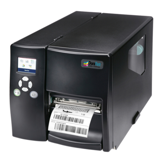
EZ2250i/EZ2350i BARCODE PRINTER
USER MANUAL
1
Related Manuals for Godex EZ2250i
Summary of Contents for Godex EZ2250i
-
Page 1
EZ2250i/EZ2350i BARCODE PRINTER USER MANUAL User Manual : EZ2250i series Version : Rev. E Issue Date : 2013.11.28 : 920-014611-00… -
Page 2: Table Of Contents
EZ2250i/EZ2350i USER MANUAL CONTENTS 1. BOX CONTENT …………….1 Box Content ………………….. 1 Getting to Know Your Printer ……………… 2 2. PRINTER SETUP …………….4 2-1. Loading the label roll ………………..4 2-2. Loading the ribbon………………….. 7 2-3. Connecting the printer to the host computer …………8 Installing Printer Driver and GoLabel with Super Wizard CD ……..
-
Page 3
EZ2250i/EZ2350i USER MANUAL FCC COMPLIANCE STATEMENT FOR AMERICAN USERS This equipment has been tested and found to comply with the limits for a CLASS A digital device, pursuant to Part 15 of the FCC Rules. These limits are designed to provide reasonable protection against harmful interference when the equipment is operated in a commercial environment. -
Page 4: Safety Instructions
EZ2250i/EZ2350i USER MANUAL SAFETY INSTRUCTIONS Please read the following instructions carefully. Keep the equipment away from humidity. Before you connect the equipment to the power outlet, please check the voltage of the power source. Make sure the printer is off before plugging the power connector into the power jack.
-
Page 5: Box Content
Barcode Printer Box Content Please check that all of the following items are included with your printer. EZ2250i/EZ2350i Barcode Printer Label Stock USB Cable EZ2250i Series Quick Guide Ribbon Module Power Adapter Empty Ribbon Core Power Cord …
-
Page 6: Getting To Know Your Printer
Barcode Printer Getting to Know Your Printer External view Operator panel Lower cover plate Viewing window Printer cover Feed slot for continuous labels Auto-Calibration button Parallel port (optional) Applicator interface (optional) USB Host N Ethernet port USB port Serial port (DB-9) Power jack On/Off switch Feed slot for continuous labels…
-
Page 7
Barcode Printer Internal view Ribbon rewind hub Ribbon supply hub Print mechanism Platen roller Tear-off plate Release lever for print head Adjustment wheel for sensor Paper guide Label tension guide Label supply hub Label roll guide Release catch Movable sensor… -
Page 8: Printer Setup
Printer Setup Loading the label roll This printer supports the following printing methods: Thermal transfer printing (TTP):Requires a ribbon for transferring a printed image to a medium. Direct thermal printing (DTP):Does not require a ribbon, only thermal paper. Please check which printing method you are using and alter the settings accordingly in the printer driver, printer menu, and/or software.
-
Page 9
Printer Setup Place the label roll on the label supply hub, pushing it right up to the printer housing. (Do not apply too much pressure to avoid damaging the label stock.) Fold the label roll guide back down and push it against the label roll. -
Page 10
Printer Setup The labels pass between the wall of the printer housing and the adjustable paper guide. Note 【 】 Pass the labels through the printer as shown in the illustration. 10. Return the print head release lever to its original position. -
Page 11: Loading The Ribbon
Printer Setup Loading the Ribbon 1. Place the printer on a flat surface and open the printer cover. 2. Pull out the print head release lever as shown in the illustration (1) and turn it anticlockwise to a top right position (2).
-
Page 12: Connecting The Printer To The Host Computer
Printer Setup Connecting the Printer to the Host Computer Please make sure that the printer is switched off. Connect the power cord to the AC adapter and connect the adapter to the printer. Connect the USB cable to the printer and host computer. Switch on the printer.
-
Page 13: Installing Printer Driver And Golabel With Super Wizard Cd
Printer Setup Installing Printer Driver and GoLabel with Super Wizard CD Insert the Super Wizard CD in the CD/DVD drive of the host computer and the program should pop up automatically. You will see the Welcome screen first. On the Welcome screen, choose “Standard Installation”. The wizard will then ask you to make sure your USB and power cables are connected and that the power is turned on.
-
Page 14
Printer Setup As the printer driver and GoLabel are installing, a screen will display a progress bar. Once the installation is complete, you can start to make and print labels with GoLabel or throug the printer driver. As the optional steps, you can also print a test label or register your printer during the “Standard Installation” procedure. -
Page 15
Insert the product CD in the CD/DVD drive of the host computer and open the «Seagull Drivers» folder on the CD. Select the icon for the driver file and click it to start the installation. Follow the instructions on the screen. The Driver Wizard guides you through the installation procedure. Select «Install printer drivers». Specify your printer model. Godex EZ2250i… -
Page 16
Printer Setup Specify the port used to connect the printer to the host computer. Enter a printer name and assign the appropriate rights. Godex EZ2250i Godex EZ2250i Once the installation is complete, a summary of the printer settings is displayed. -
Page 17
Printer Setup Once the driver installation is complete, the new printer should appear in the «Printers and Faxes» folder. Godex EZ2250i Godex EZ2250i… -
Page 18: Printer Setting And Control
Printer Setting and Control Operation Panel Operation Panel Introduction LCD SCREEN OPERATION PANEL DIRECTION KEY FEED BUTTON POWER BUTTON POWER Button Press the POWER button to turn on the printer, and the START UP SCREEN appears. The printer is on “ready to print” status, the LCD screen should display the message “READY“…
-
Page 19: Lcd Interface Introduction
Setting and Control for Operation Panel LCD Interface Introduction Getting Started Press the POWER button to turn on the printer, and the START UP SCREEN appears. Power on If the printer is on “ready to print” status, the LCD screen should display the message “Ready“ on the screen. Please keep pressing …
-
Page 20
Setting and Control for Operation Panel Operations on Setting Page On MAIN PAGE, press or button to move the cursor and select the functions. Select a designated function and press FEED button, you will enter the SETTING PAGES for the function. Select Enter On SETTING PAGES, press … -
Page 21
Setting and Control for Operation Panel On SETTING VALUE PAGES, press or button to change the setting values. Select Press FEED button will apply the setting value you just selected, and the red tick will appear to mark the value. Apply **** The blue arrow indicates the value you are selected. -
Page 22
Setting and Control for Operation Panel Exit from Current Page to Ready Status The icon on top-left corner displays the capture of upper level screen and also guides you back to upper level with left or up arrow. NAVIGATION ICON On SETTING VALUE PAGES, press button will go back to the upper level screen. -
Page 23
Setting and Control for Operation Panel On MAIN PAGE, select the “EXIT” icon and press the FEED button to exit from SETTING MODE and the printer goes back to READY status. EXIT from Setting Mode Back to the Ready status… -
Page 24: Lan Setting
Setting and Control for Operation Panel LAN Setting Operations on Setting Page On MAIN PAGE,press or button to move the cursor and select the functions. Select a designated function and press FEED button, you will enter the SETTING PAGES for the function. Select Device Device Enter LAN Setting…
-
Page 25
Setting and Control for Operation Panel The default of DHCP is Disable. ,Press or button to change the setting values. Select to enable DHCP Press FEED button twice to save the setting. Press FEED once to exit. Press FEED again to save and return to previous SETTING PAGE. -
Page 26: Lcd Password
Setting and Control for Operation Panel LCD Password Operations on Setting Page On MAIN PAGE, press or button to move the cursor and select the functions. Seclect a designated function and press FEED button, you will enter the SETTING PAGE for the function. Select Device Device Enter LCD Password…
-
Page 27
Setting and Control for Operation Panel Select button again to setup the password Press FEED button twice to svae the setting Press FEED button onece to exit. Press FEED button again to save and reture to previous SETTING PAGE… -
Page 28: Lcd Interface Function
Setting and Control for Operation Panel LCD Interface Function Main Page Setting items for printer, ex. Printing speed, darkness. Also includes a Printing Wizard for your ease of printing. Printer Setting Setting items for printing label, ex. Rotation, Printing position offset. Label Setting Option modules and connection port settings.
-
Page 29
Setting and Control for Operation Panel Setting Items in Setting Mode English Deutsch LCD Language 繁體中文 简体中文 Printer Setting Français Español German 日本語 Italiano Pусский Türk Speed 2-5 or 7 Darkness 0-19 Label with Gaps Media Type Label with Marks Wizard Continuous Direct Thermal… -
Page 30
Setting and Control for Operation Panel Apply Buzzer Cancel None Cutter Option Device Label Dispensor Optional Setting Applicator Apply Pre-Printing Cancel 09100 Part NO. Disable DHCP Enable LAN Setting Default Gateway 192.168.000.254 Dynamic IP 192.168.102.076 Subnet Mask 255.255.255.000 Disable LCD Password Enable 4800 bps 9600 bps… -
Page 31
Setting and Control for Operation Panel Status of LCD Interface When printer is on standby status (ready to print), the LCD interface will display “Ready” on screen. You can only print on this “Ready“ status. If there is any printers error, the LCD screen will display the error screen to show the type of error. You can fix the error according the notice. -
Page 32: Label Calibration And Self Test
The printer will now measure the label stock and store the label height. Once the printer has successfully measured the label stock, it will print a self-test label. The contents of a self-test printout are listed below. EZ2250i:GX.XXX Model & Version USB S/N:12345678…
-
Page 33
Setting and Control for Operation Panel Label Calibration Button A hardware button to make a Label Calibration while printer encountering ‘’Media Error’’ during the cases when first-time printer start up or change label or ribbon to another type, such as change using gap label to continuous or black mark labels. -
Page 34: Dump Mode
Setting and Control for Operation Panel Dump mode If the label settings do not match the printer output, you can switch the printer to dump mode to check whether an error has occurred during the transfer between printer and host computer. In dump mode, the unprocessed raw data are sent to the printer and printed.
-
Page 35: Error Alerts
Setting and Control for Operation Panel Error Alerts In the event of a problem that prevents normal functioning of the printer, you will see an error message on LCD screen and hear some beep signals. Please refer to below table for the error alerts. LCD SCREEN OPERATION PANEL DIRECTION KEY…
-
Page 36
Setting and Control for Operation Panel Operation Panel Status Type Beeps Description Solution The memory is full. The printer Delete unnecessary data or install prints the message «File System full additional memory. «. Use the «~X4» command to print Unable to find file. The printer all files. -
Page 37: Usb Host
USB memory stick : It supports hot-plugging function; printer will create a Folder ‘’LABELDIR’’ and switch ‘’User Flash’’ to ‘’ Extended Memory‘’ automatically while user plugs an USB memory stick into a GoDEX ‘’i’’ model printer. Connect the USB Stick plugged -in printer to PC via USB Device or Ethernet port and run ‘’GoLabel’’ software to …
-
Page 38
Setting and Control for Operation Panel USB Keyboard When plug-in an USB keyboard to the printer, LCD panel will display “Standalone Mode”, press the “Enter” key on keyboard and “Feed” key in the printer to entering to the dialog for “Recall Label” operation. Only the sub-dialog “Recall Label”… -
Page 39: Netsetting For Ethernet
NetSetting for Ethernet Installing the NetSetting software The NetSetting software is used to manage the network configurations when connecting the printer via Ethernet port. It is available on product CD or can be downloaded from official website. To install the NetSetting, please follow below steps.
-
Page 40: The Interface Of Netsetting
PC. RT700i Click the magnifier icon to search the Godex printers which are connected via Ethernet port in you network environment. Once a connected Godex printer is detected, it will be listed on the start page.
-
Page 41
NetSetting for Ethernet IP Setting The IP Setting tab can change the printer name, Port number, Gateway setting and the password for configuring the printer. You can also set the printer’s IP address ether by DHCP or by Static IP. You can press “Set”… -
Page 42
NetSetting for Ethernet Alert Path Setting NetSetting will send the alert messages to designated mail account when the error happened on printer. The alert messages are sent by SMTP (Simple Mail Transfer Protocol) or SNMP (Simple Network Management Protocol). You can set or change the configurations of SMTP and SNMP on this “Alert Path Setting” tab. You can press “Set”… -
Page 43
NetSetting for Ethernet Alert Message Setting For the alert message notification function, you can decide which error cases need to be sent out to the operator. Moreover, the alert messages can be set to be sent by SMTP, SNMP or both. You can press “Set”… -
Page 44
NetSetting for Ethernet Printer Configuration Set or change the configurations of connected printer. Most of key settings for the printer operation can be done by this setting page. RT700i You can press “Set” button to apply the settings and “ReGet” button to refresh the setting values. -
Page 45
NetSetting for Ethernet User Command The “User Command” tab provides a communication interface for operator to control the printer. Input printer commands in «Input Command» window and press “Send Command” button, the commands will be sent to the printer. For some commands that will return response message, the message will be displayed in «Output Message» window. You can press “Send Command”… -
Page 46
NetSetting for Ethernet Firmware Download On “Firmware Download” tab, the current version of printer firmware will be showed on the screen. If you need to update the printer firmware, just specify the file location of firmware file and press “Start Download Firmware” button. The printer firmware then can be updated remotely. -
Page 47: Accessories
Accessories Internal rewinder Rewinder Retention clip Screws (set of 4) Rewinder guide Note 【 】 Maximum height of the rewound medium: 118 mm Suggestion 【 】 Medium thickness: 0.06 mm– 0.25 mm Place the printer on a flat surface and open the printer cover.
-
Page 48
Accessories Remove the retention clip from the rewinder. Secure the rewinder on the printer housing using the four screws supplied. Now connect the rewinder cable to the printer housing. Installation of the rewinder module is now complete. -
Page 49: Installing The Rewinder Guide
Accessories Installing the rewinder guide Unscrew the screw marked in the illustration on the front of the printer, which secures the lower cover plate. Remove the lower cover plate. Note 【 】 Switch off the printer before starting the installation. Mount the rewinder guide on the print mechanism and secure it with screws.
-
Page 50: Label Dispenser
Accessories Label dispenser Unscrew the screw marked in the illustration on the front of the printer, which secures the lower cover plate. Remove the lower cover plate. Note 【 】 Switch off the printer before starting the installation. Place the printer the right way up again.
-
Page 51
Accessories Wind the label liner around the rewinder and secure it using the retention clip. Return the print head release lever to its original position. Note 【 】 Please make sure that the label stock rewinds the right way onto the rewind hub. 10. -
Page 52: Installing The Cutter
Accessories Installing the cutter Cutter cover Cutter module Cable clips Screws (set of 4) Note 1 【 】 Remember to switch off the printer before installing the cutter. Note 2 【 】 Do not use to cut adhesive labels! Glue residue will be left on the cutter blade and impair its functioning.
-
Page 53
Accessories Secure the cutter module on the printer housing using the screws. Connect the cutter cable connector to the cutter jack on the printer. Route the connection cable along the bottom of the printer housing using the cable clips. Place the cutter cover over the cutter module and secure it using the screw you removed from the lower… -
Page 54: Installing The Parallel Adapter
Accessories Installing the Parallel adapter Parallel cable Parallel adapter Connection cable Screws (set of 2) Check whether the printer is switched off. Place the printer on a flat surface and open the printer cover. Unscrew the two screws marked in the illustration on the right and remove the left-hand side of the printer housing.
-
Page 55
Accessories Install the Parallel adapter in its place and secure it on the housing with screws. Connect the 30-pin connection cable to the motherboard. Replace the left-hand part of the printer housing and secure it with the screws you removed earlier. Installation of the Parallel adapter is now complete. -
Page 56: Maintenance And Adjustment
Maintenance and Adjustment Installing / removing the print head module Open the printer cover. Note 【 】 Remember to switch off the printer before removing the print head module. Pull out the print head release lever as shown in the illustration (1) and turn it anticlockwise to a top right position (2).
-
Page 57: Adjusting The Print Line
Maintenance and Adjustment Adjusting the print line Please contact your local dealer for technical support. Open the printer cover. Pull out the print head release lever as shown in the illustration (1) and turn it anticlockwise to a top right position (2). TPH print line adjustment: When printing is slow or …
-
Page 58: Adjusting The Ribbon Tension
Maintenance and Adjustment Adjusting the print line You can adjust the ribbon tension by turning the ribbon shaft knob (green wheel at the base of the ribbon supply hub – see illustration) clockwise or anticlockwise. There are 4 possible settings, which are marked on the knob of the ribbon rewind hub and the ribbon supply hub.
-
Page 59: Cleaning The Thermal Print Head
Maintenance and Adjustment Cleaning the thermal print head Dirt on the print head or ribbon may result in inadequate print quality (no printed image on part of the label). The printer cover should therefore be kept closed whenever possible. Keeping dirt and dust away from the paper or labels ensures a good print quality and a longer lifespan of the print head.
-
Page 60: Adjusting The Balance And Print Head Tension
Maintenance and Adjustment Adjusting the balance and print head tension Open the printer side cover. Pull out the print head release lever as shown in the illustration (1) and turn it anticlockwise to a top right position (2). When using a variety of label stock and ribbons, the ink may not be evenly distributed.
-
Page 61: Ribbon Shield Settings
Maintenance and Adjustment Ribbon shield settings The use of different ribbon materials may cause wrinkling of the ribbon, which in turn affects the print result as illustrated by the examples in (a) and (b). To change the print quality, you can adjust the ribbon shield screws. If your print result looks like the example in (a), you need to turn ribbon shield screw A clockwise.
-
Page 62: Cutter Settings
Maintenance and Adjustment Cutter settings Socket head screws for adjusting the cutter are located on both sides of the cutter. In the event of a paper jam, the cutter will no longer function correctly. Switch off the printer and use a hex key (#M3) to turn the socket head screw.
-
Page 63: Troubleshooting
Maintenance and Adjustment Troubleshooting Problem Solution ♦ Check the power supply. The printer is switched on but the LED does not light up. Please see the Section 2.4 Check the software settings (driver settings) or command codes. ♦ Look for the error alert in the table in Section 3.3. Error Alerts. ♦…
-
Page 64: Appendix
* **Minimum print height and maximum print speed specification compliance can be dependent on non-standard material variables such as label type, thickness, spacing, liner construction, etc. Godex is pleased to test non-standard materials for minimum print height and maximum print speed capability.
-
Page 65
EZ2250i/EZ2350i USER MANUAL APPENDIX INTERFACE Parallel port Handshaking : DSTB is sent to the printer, BUSY to the host computer Interface : Parallel cable compatible with IBM computers cable Pinout : See below Pin No. Function Transmitter /Strobe Computer / printer… -
Page 66
EZ2250i/EZ2350i USER MANUAL APPENDIX INTERFACE Connector Type : Type B Pin NO. Function VBUS Internal interface UART1 wafer Ethernet module E_MD E_MD E_RST E_RST UART2 wafer Add-on module Appendix… -
Page 67
EZ2250i/EZ2350i USER MANUAL APPENDIX FILE MANIPULATION WHEN USING USB STICK File Manipulation The files in both devices (USB memory stick and printer internal Flash memory) are able to copy and move by the commands ‘’~MCPY’’ and ‘’MMOV’’ that sends from GoLabel on a PC via either connection — USB or Ethernet ports.
This manual is also suitable for:
Ez2350i
Посмотреть инструкция для Godex EZ2250i бесплатно. Руководство относится к категории Принтеры для этикеток, 2 человек(а) дали ему среднюю оценку 7.2. Руководство доступно на следующих языках: английский. У вас есть вопрос о Godex EZ2250i или вам нужна помощь? Задайте свой вопрос здесь
Не можете найти ответ на свой вопрос в руководстве? Вы можете найти ответ на свой вопрос ниже, в разделе часто задаваемых вопросов о Godex EZ2250i.
Что означает аббревиатура DPI?
Какие сертификаты Godex EZ2250i имеет?
Какая высота Godex EZ2250i?
Какая ширина Godex EZ2250i?
Какая толщина Godex EZ2250i?
Инструкция Godex EZ2250i доступно в русский?
Не нашли свой вопрос? Задайте свой вопрос здесь
Смотреть руководство для Godex EZ2250i ниже. Все руководства на ManualsCat.com могут просматриваться абсолютно бесплатно. Нажав кнопку «Выбор языка» вы можете изменить язык руководства, которое хотите просмотреть.

MANUALSCAT | RU
Вопросы и ответы
У вас есть вопрос о Godex EZ2250i, но вы не можете найти ответ в пользовательском руководстве? Возможно, пользователи ManualsCat.com смогут помочь вам и ответят на ваш вопрос. Заполните форму ниже — и ваш вопрос будет отображаться под руководством для Godex EZ2250i. Пожалуйста, убедитесь, что вы опишите свои трудности с Godex EZ2250i как можно более детально. Чем более детальным является ваш вопрос, тем более высоки шансы, что другой пользователь быстро ответит на него. Вам будет автоматически отправлено электронное письмо, чтобы проинформировать вас, когда кто-то из пользователей ответит на ваш вопрос.
Задать вопрос о Godex EZ2250i
- Бренд:
- Godex
- Продукт:
- Принтеры для этикеток
- Модель/название:
- EZ2250i
- Тип файла:
- Доступные языки:
- английский
Сопутствующие товары Godex EZ2250i
3
Setting and Control for Operation Panel
Operation Panel
Status
Type
Beeps
File Error
2 x 2 beeps
Description
The memory is full. The printer
prints the message «File System full
«.
Unable to find file. The printer
prints the message «File Name not
found»
A file of the same name already
exists. The printer prints the
message «Duplicate Name».
32
Solution
Delete unnecessary data or install
additional memory.
Use the «~X4» command to print
all files. Then check whether the
files exist and whether the names
are correct.
Change the name of the file and
try storing it again.
Page 1 — USER MANUAL
1EZ2250i/EZ2350i BARCODE PRINTERUSER MANUALUser ManualVersionIssue DateP/N : EZ2250i series : Rev. E : 2013.11.28 : 920-014611-00
Page 2 — CONTENTS
62 Printer Setup9. The labels pass between the wall of the printer housing and the adjustable paper guide. 【Note】 Pass the labels through the pri
Page 3 — Decleration
72 Printer Setup2.2 Loading the Ribbon1. Place the printer on a flat surface and open the printer cover. 2. Pull out the print head release l
Page 4 — SAFETY INSTRUCTIONS
82 Printer Setup2.3 Connecting the Printer to the Host Computer1. Please make sure that the printer is switched off.2. Connect the power c
Page 5 — 1 Barcode Printer
92 Printer Setup* If the Super Wizard program did not run automatically, you can either turn on the “Auto-run” setting for your CD/DVD driver
Page 6
102 Printer Setup4. As the printer driver and GoLabel are installing, a screen will display a progress bar.5. Once the installation is comple
Page 7
111. Insert the product CD in the CD/DVD drive of the host computer and open the «Seagull Drivers» folder on the CD. Select the ic
Page 8
122 Printer Setup2 Printer Setup4. Specify the port used to connect the printer to the host computer.6. Once the installation is complete,
Page 9
132 Printer Setup7. Once the driver installation is complete, the new printer should appear in the «Printers and Faxes» folder.Godex E
Page 10 — 2 Printer Setup
143 Printer Setting and Control3.1 Operation PanelOperation Panel IntroductionFEED ButtonWhen you press the FEED button, the printer moves the l
Page 11
153 Setting and Control for Operation Panel3.2 LCD Interface IntroductionGetting StartedPress the POWER button to turn on the printer, and the S
Page 12
ContentsEZ2250i/EZ2350i USER MANUALCONTENTSContents1. BOX CONTENT … 1 1.1
Page 13
163 Setting and Control for Operation PanelOperations on Setting PageOn MAIN PAGE, press or button to move the cursor and select the functions.
Page 14
173 Setting and Control for Operation PanelPress FEED button will apply the setting value you just selected, and the red tick will appear to mark t
Page 15
18On SETTING PAGES, press button will go back to the MAIN PAGE screen.Exit from Current Page to Ready StatusThe icon on top-left corner displays the
Page 16 — Godex EZ2250i
19On MAIN PAGE, select the “EXIT” icon and press the FEED button to exit from SETTING MODE and the printer goes back to READY status.orEXIT from Setti
Page 17
203.3 LAN SettingOperations on Setting PageOn MAIN PAGE,press or button to move the cursor and select the functions.Select a designated functio
Page 18 — Calibration and Self Test
213 Setting and Control for Operation PanelThe default of DHCP is Disable. ,Press or button to change the setting values.Press FEED button twic
Page 19
223 Setting and Control for Operation Panel3.4 LCD PasswordOperations on Setting PageOn MAIN PAGE, press or button to move the cursor and se
Page 20
233 Setting and Control for Operation PanelSelect button again to setup the password Press FEED button onece to exit.Press FEED button twice to s
Page 21
243 Setting and Control for Operation Panel3.5 LCD Interface FunctionMain PagePrinter SettingLabel SettingDeviceAnalysisExitSetting items for pr
Page 22 — NAVIGATION ICON
253 Setting and Control for Operation PanelSetting Items in Setting ModePrinter SettingLabel SettingLCD Language English German 繁體中文 简体中文 Wizard Sp
Page 23 — Back to the Ready status
EZ2250i/EZ2350i USER MANUALFCC COMPLIANCE STATEMENTFOR AMERICAN USERSThis equipment has been tested and found to comply with the limits for a CLASS A
Page 24 — 3.3 LAN Setting
26DeviceAnalysisExitBuzzer Apply Cancel Optional Setting Option None Cutter Label Dispensor Applicator Pre-Printing Apply Cancel Serial Port Setting B
Page 25
27Status of LCD InterfaceWhen printer is on standby status (ready to print), the LCD interface will display “Ready” on screen.You can only print on th
Page 26 — 3.4 LCD Password
283 Setting and Control for Operation Panel3.6 Label Calibration and Self TestLabel CalibrationThe printer can automatically detect and store la
Page 27
293 Setting and Control for Operation PanelLabel Calibration ButtonA hardware button to make a Label Calibration while printer encountering ‘’Media
Page 28 — 3.5 LCD Interface Function
303 Setting and Control for Operation Panel3.7 Dump modeIf the label settings do not match the printer output, you can switch the printer to dum
Page 29 — Français
313 Setting and Control for Operation Panel3.8 Error AlertsIn the event of a problem that prevents normal functioning of the printer, you will s
Page 30 — Analysis
323 Setting and Control for Operation PanelOperation Panel Status Type Beeps Description Solution File Error 2 x 2 beeps The memory is full. The
Page 31 — Check Ribbon
333 Setting and Control for Operation Panel3.9 USB HostDefinition : USB Host port supports either device:USB memory stick, keyboard or scanner.P
Page 32
343 Setting and Control for Operation Panel** The USB Host port on ‘’i’’ ‘’x’’ model printer is without ‘’HUB’’ function.** The USB Memory Stic
Page 33 — CALIBRATION BUTTON
354 NetSetting for Ethernet4.1 Installing the NetSetting softwareThe NetSetting software is used to manage the network configurations when conne
Page 34 — 3.7 Dump mode
EZ2250i/EZ2350i USER MANUALSAFETY INSTRUCTIONSPlease read the following instructions carefully.1. Keep the equipment away from humidity.2. Befor
Page 35 — 3.8 Error Alerts
364 NetSetting for Ethernet4.2 The Interface of NetSettingClick the NetSetting icon to start the program; you will see the start page as below.
Page 36 — Operation Panel
37**** To fully benefit from the NetSetting software, you should be familiar with basic networking principles. Please contact your network admi
Page 37 — 3.9 USB Host
38You can press “Set” button to apply the settings and “ReGet” button to refresh the setting values.Alert Path SettingNetSetting will send the alert m
Page 38
39You can press “Set” button to apply the settings and “ReGet” button to refresh the setting values.Alert Message SettingFor the alert message notific
Page 39 — 4 NetSetting for Ethernet
40You can press “Set” button to apply the settings and “ReGet” button to refresh the setting values.Printer ConfigurationSet or change the configurati
Page 40
41You can press “Send Command” button to send printer commands via Ethernet port and control the printer remotely.User CommandThe “User Command” tab p
Page 41 — NetSetting for Ethernet
42In addition to the firmware update, you can press “Recover To Factory Settings” button to restore the printer configurations back to factory default
Page 42
435 Accessories5.1 Internal rewinder1 Rewinder 1234 2 Retention clip 3 Screws (set of 4) 4 Rewinder guide 【Note】 Maximum height of the rewound m
Page 43 — Alert Message Setting
445 Accessories3. Remove the retention clip from the rewinder. 4. Secure the rewinder on the printer housing using the four screws supplied. 12
Page 44
455 Accessories5.2 Installing the rewinder guide1. Unscrew the screw marked in the illustration on the front of the printer, which secures the
Page 45
11 Barcode Printer1.1 Box ContentPlease check that all of the following items are included with your printer.EZ2250i/EZ2350i Barcode PrinterUSB
Page 46
465 Accessories5.3 Label dispenser1. Unscrew the screw marked in the illustration on the front of the printer, which secures the lower cover pl
Page 47 — 5 Accessories
475 Accessories8. Wind the label liner around the rewinder and secure it using the retention clip. 9. Return the print head release lever to its
Page 48
485 Accessories5.4 Installing the cutter1 Cutter cover 2 Cutter module 3 Cable clips 4 Screws (set of 4) 【Note 1】 Remember to switch off the pr
Page 49
495 Accessories3. Secure the cutter module on the printer housing using the screws. 4. Connect the cutter cable connector to the cutter jack on
Page 50
505 Accessories5.5 Installing the Parallel adapter1 Parallel cable 123 4 2 Parallel adapter 3 Connection cable 4 Screws (set of 2) 1. Check wh
Page 51
515 Accessories4. Install the Parallel adapter in its place and secure it on the housing with screws. 5. Connect the 30-pin connection cable to t
Page 52
526 Maintenance and Adjustment6.1 Installing / removing the print head module1. Open the printer cover. 【Note】 Remember to switch off the print
Page 53
536 Maintenance and Adjustment6.2 Adjusting the print linePlease contact your local dealer for technical support. 1. Open the printer cover.
Page 54
546 Maintenance and Adjustment6.3 Adjusting the print lineYou can adjust the ribbon tension by turning the ribbon shaft knob (green wheel at the
Page 55
556 Maintenance and Adjustment6.4 Cleaning the thermal print headDirt on the print head or ribbon may result in inadequate print quality (no pri
Page 56
21 Barcode Printer1.2 Getting to Know Your PrinterExternal view 1. Operator panel 2. Lower cover plate 3. Viewing window 4. Printer cov
Page 57
566 Maintenance and Adjustment6.5 Adjusting the balance and print head tension1. Open the printer side cover. 2. Pull out the print head relea
Page 58
576 Maintenance and Adjustment6.6 Ribbon shield settings1. The use of different ribbon materials may cause wrinkling of the ribbon, which in tu
Page 59
586 Maintenance and Adjustment6.7 Cutter settings1. Socket head screws for adjusting the cutter are located on both sides of the cutter. 2. I
Page 60
Appendix6 Maintenance and Adjustment6.8 Troubleshooting**** If any problems occur that are not described here, please contact your dealer.Proble
Page 61 — 6.6 Ribbon shield settings
AppendixEZ2250i/EZ2350i USER MANUALAPPENDIXPRODUCT SPECIFICATIONS****Specifications are subject to change without notice. All company and/or product n
Page 62 — 6.7 Cutter settings
AppendixAppendixINTERFACESerial PortDefault settings: Baud rate 9600, no parity, 8 data bits, 1 stop bit, XON/XOFFprotocol and RTS/CTS RS232 Housing(
Page 63 — 6.8 Troubleshooting
AppendixINTERFACEEZ2250i/EZ2350i USER MANUALAPPENDIXConnector Type : Type B USBPin NO. 1 2 3 4 Function VBUS D- D+ GND Internal interfaceUART1 w
Page 64 — APPENDIX
AppendixFILE MANIPULATION WHEN USING USB STICKEZ2250i/EZ2350i USER MANUALAPPENDIXFile Manipulation The files in both devices (USB memory stick and
Page 65
31 Barcode PrinterInternal view 1. Ribbon rewind hub 2. Ribbon supply hub 3. Print mechanism 4. Platen roller 5. Tear-off plate 6.
Page 66
42 Printer SetupThis printer supports the following printing methods:Thermal transfer printing (TTP):Requires a ribbon for transferring a printed i
Page 67
52 Printer Setup5. Place the label roll on the label supply hub, pushing it right up to the printer housing. (Do not apply too much pressure to av

1
EZ2250i/EZ2350i BARCODE PRINTER
USER MANUAL
User Manual
Version
Issue Date
P/N
: EZ2250i series
: Rev. E
: 2013.11.28
: 920-014611-00