Furuno ECDIS Operator’s Manual (Russian) / Furuno ЭКНИС Руководство Оператора FEA-2807/2107/2107-BB [PDF]
Год выпуска: 2004
Язык: русский
Автор: Furuno
Жанр: Руководство
Формат: PDF
Качество: Изначально компьютерное (eBook)
Количество страниц: 582
Описание: ЭКНИС серииFEA-2107 – это продукт огромного опыта фирмыFURUNO в области компьютерной технологии и
морской электроники. Он отвечает требованиям РезолюцииIMO A.817(9), IEC 61174 и другим соответствующим
стандартам. ЭКНИС отображает электронные карты, навигационные линии, данные САРП, цели АИС и другие
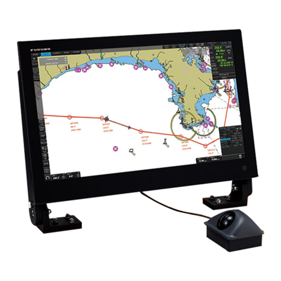
навигационные данные на дисплее с высоким разрешением размером20.1 дюйма(FEA-2107) или23.1 дюйма(FEA-2807). FEA-2107-BB поставляется без монитора, позволяя вам использовать покупной монитор по своему выбору.
Основные особенности ЭКНИС следующие
• Непрерывный мониторинг позиции судна через обработку многоканальным фильтром Кальмана с
использованиемGPS, DPGS, SDME (морское оборудование измерения скорости и пройденного расстояния)
• Функции предварительной прокладки(планирования) и мониторинга маршрута
• Широкий спектр функций предупреждения, обеспечивающих более безопасную и эффективную навигацию
• Возможность наложения радиолокационного изображения на электронные карты(факультативная)
• Предупреждения о возможности посадки на мель, безопасные изобаты
• Картографическая база данных, загружаемая и обновляемая при помощиCD ROM
• Данные цели от РЛС/САРП и транспондера АИС, помогающие избежать столкновение. (Транспондер АИС и
САРП)
Настоящее руководство приводит следующую информацию:
• Конфигурация системы
• Интерпретация экрана и использование блока управления
• Подготовка к выходу в рейс
• Правила замены бумажных карт электронными
• Управление картографическим материалом
• Ручные обновления, которые используются для ручного ввода Извещений мореплавателям и предупреждений
Navtex
• Расчет картографических тревог
• Предварительная прокладка(планирование) и мониторинг маршрута
• Различные инструменты пользователя, такие как карты пользователя, лоцманские данные и навигационные
инструменты
• Операции по созданию резервных копий
• Общая Справочная Система
• Использование навигационных датчиков
• Использование целей САРП
• Использование целей АИС
• Наложение радиолокационного изображения
• Различные функции записи
• Обязательная информация о принятой системе координат, используемой картами и ЭКНИС
• Операции, связанные с управлением судном
• Список тревог
Содержание
Смотрите скриншоты
Скриншоты
-
Contents
-
Table of Contents
-
Troubleshooting
-
Bookmarks
Quick Links
OPERATOR’S MANUAL
ELECTRONIC CHART
DISPLAY AND
INFORMATION SYSTEM
(ECDIS)
FMD-3100
Model
www.furuno.com
Related Manuals for Furuno FMD-3100
Summary of Contents for Furuno FMD-3100
-
Page 1
OPERATOR’S MANUAL ELECTRONIC CHART DISPLAY AND INFORMATION SYSTEM (ECDIS) FMD-3100 Model www.furuno.com… -
Page 2
・FURUNO Authorized Distributor/Dealer 9-52 Ashihara-cho, Nishinomiya, 662-8580, JAPAN A : FEB 2014 Printed in Japan All rights reserved. E : DEC . 05, 2017 Pub. No. OME-44840-E ( GREG ) FMD-3100 0 0 0 1 7 8 7 5 5 1 4… -
Page 3: Important Notices
How to discard a used battery Some FURUNO products have a battery(ies). To see if your product has a battery, see the chapter on Maintenance. Follow the instructions below if a battery is used. Tape the + and — terminals of battery before disposal to prevent fire, heat generation caused by short circuit.
-
Page 4
SAFETY INSTRUCTIONS The operator must read the safety instructions before attempting to operate the equipment. Indicates a potentially hazardous situation which, if not avoided, WARNING could result in death or serious injury. Indicates a potentially hazardous situation which, if not avoided, CAUTION could result in minor or moderate injury. -
Page 5: Table Of Contents
TABLE OF CONTENTS FOREWORD ……………………xi SYSTEM CONFIGURATION ………………xiii INTRODUCTION ………………..1-1 1.1 System Configuration ………………..1-1 1.2 Panel Computer Unit ………………..1-1 1.3 Trackball Control Unit ………………..1-3 1.4 DVD Drive……………………1-3 1.5 How to Turn the Power On or Off …………….1-3 1.6 How to Select a Color Palette………………1-4 1.7 How to Adjust the Display Brilliance …………….1-5 1.8 Silent Mode…………………….1-6 1.9 How to Select Sensor Settings ……………….1-7…
-
Page 6
TABLE OF CONTENTS 2.4 How to Select the Presentation Mode…………..2-19 2.5 Cursor Position Box ………………..2-20 2.6 True Motion Reset………………..2-21 2.7 How to Control Route and User Charts in Voyage Navigation and Voyage Planning Modes ………………….. 2-22 2.8 How to Use the VRM and EBL…………….. 2-23 2.8.1 How to hide/show an EBL, VRM ………….. -
Page 7
TABLE OF CONTENTS 3.18 How to Print Chart List, Cell Status List…………..3-24 3.18.1 How to print the chart list …………….3-24 3.18.2 How to print the cell status list …………..3-25 3.19 How to Delete Charts ………………..3-26 3.20 How to Show Publishers Notes for ENC Charts…………3-27 3.21 How to Find the Chart Type………………3-28 3.22 How to Update ENC, C-MAP Charts Manually…………3-28 3.22.1 How to insert update symbols …………..3-29… -
Page 8
TABLE OF CONTENTS RASTER (ARCS) CHARTS ……………….6-1 6.1 ARCS Charts………………….6-1 6.1.1 Chart legend of ARCS chart…………….6-1 6.2 Datum and ARCS Charts ………………. 6-5 6.3 Permanent Warnings of ARCS ……………… 6-5 6.4 ARCS Subscriptions………………..6-6 6.4.1 ARCS Navigator………………… 6-6 6.4.2 ARCS license information ……………. -
Page 9
TABLE OF CONTENTS 9.10 How to Export Route Data………………9-21 9.10.1 How to export FMD-3xx0 route data …………9-21 9.10.2 How to export route data in FEA-2×07, RTZ, CSV, ASCII format ….9-22 9.11 How to Delete Routes………………..9-22 9.12 How to Transfer Routes………………..9-23 9.13 Reports ……………………9-25 10. -
Page 10
TABLE OF CONTENTS 12.3 Look-ahead ………………….12-5 12.4 Ring…………………….. 12-5 12.5 Predictor……………………12-7 12.6 Anchor Watch………………….12-8 12.7 UKC (Under Keel Clearance)………………. 12-9 12.7.1 UKC overview ………………..12-9 12.7.2 How to set UKC………………12-10 12.7.3 UKC window………………..12-10 12.8 Curved EBL………………….12-11 12.9 Mini Conning Display ………………… -
Page 11
TABLE OF CONTENTS 15.2 Navtex Messages …………………15-3 15.2.1 How to receive Navtex messages …………..15-4 15.2.2 How to delete received Navtex messages ………..15-5 16. RADAR OVERLAY ………………..16-1 16.1 Introduction…………………..16-1 16.2 How to Activate, Setup the Radar Overlay ……………16-2 16.3 How to Adjust the Radar Signal Fed From the Radar Connection Box….16-3 16.4 Error Between Radar Echo Image and Chart…………16-7 16.5 Error Sources for Radar Echo Image and TT Mismatch ……….16-8 17. -
Page 12
TABLE OF CONTENTS 20. ALERTS …………………..20-1 20.1 What is an Alert?…………………. 20-1 20.2 Alert Box……………………20-2 20.3 Aggregated Alerts ………………..20-5 20.4 How to Temporarily Silence the Buzzer for an Alarm or Warning……20-6 20.5 How to Acknowledge an Alarm or Warning………….. 20-6 20.6 Alert List …………………… -
Page 13: Foreword
FOREWORD Congratulations on your choice of the FURUNO ECDIS (Electronic Chart Display and Information System) FMD-3100. We are confident you will see why the FURUNO name has become synony- mous with quality and reliability. Since 1948, FURUNO Electric Company has enjoyed an enviable reputation for innovative and dependable marine electronics equipment.
-
Page 14
GPL or LGPL as published by the Free Software Foundation. Please access to the following URL if you need source codes: https://www.furuno.co.jp/cgi/cnt_oss_e01.cgi. This product uses the software module that was developed by the Independent JPEG Group. -
Page 15: System Configuration
SYSTEM CONFIGURATION Single workstation Trackball Control Unit RCU-030 Serial interface Switching Hub Sensor Adapter HUB-100 MC-3000S 24 VDC USB DVD Drive Keyboard Digital IN interface 100-230 VAC Sensor Adapter 5139U (Black) MC-3020D External Monitor* , VDR* PANEL Digital OUT interface Sensor Adapter COMPUTER USB Printer,…
-
Page 16
SYSTEM CONFIGURATION Multiple workstations (max. 3) Trackball Control Unit RCU-030 USB DVD Drive Keyboard 5139U (Black) External Monitor* , VDR* USB Printer, USB Flash Drive Serial Interface (4 ports): • IEC 61162-1/2×2 (AIS, GYRO) • IEC 61162-1×2 (GPS, LOG) PANEL PANEL Switching Hub 100-230VAC… -
Page 17: Introduction
INTRODUCTION System Configuration The FMD-3100 mainly consists of the Panel Computer Unit (hereafter referred to as PCU) and Trackball Control Unit. The PCU is connected to various navigation sen- sors, and performs electronic chart operations, navigation calculations, route planning and route monitoring. The Trackball Control Unit selects items stored in the PCU and, subsequently, performs actions on those items.
-
Page 18
1. INTRODUCTION Bottom panel The bottom panel has connectors and ports for connection of external equipment. The USB ports, which carry USB 2.0 connectivity, are for connection of the Trackball Con- trol Unit, USB DVD drive, designated keyboard and printer, mouse and USB flash memory. -
Page 19: Trackball Control Unit
1. INTRODUCTION Trackball Control Unit The Trackball Control Unit consists of a trackball, scrollwheel and left and right mouse buttons. You operate the unit just like a PC mouse; roll the trackball and operate the left and right buttons and the scrollwheel to do various functions. Left button •…
-
Page 20: How To Select A Color Palette
1. INTRODUCTION How to Select a Color Palette The system provides six sets of preset color and brilliance combinations to match any ambient lighting condition. The specifications of each set are as shown in the table be- low. Palette Brilliance (%)* Text color Background color Day-gray…
-
Page 21: How To Adjust The Display Brilliance
[CALIB] button button Calibration state Not used on FMD-3100. (CALIB or UNCALIB) 2. For coarse adjustment, place the cursor at the approximate location on the slide- bar where you want to set the brilliance, then click to change the brilliance.
-
Page 22: Silent Mode
1. INTRODUCTION Silent Mode The silent mode, which requires a password to activate, deactivates the audio alarms from the ECDIS. Use this mode when the ECDIS is not required, like in a harbor. To go to the silent mode, first click the [OTHERS] button on the Status bar then click [SILENT].
-
Page 23: How To Select Sensor Settings
1. INTRODUCTION How to Select Sensor Settings This ECDIS system accepts navigation data input two ways: System or Local. System shares sensor data among multiple ECDIS in the network. Sensor priority is also com- monly shared among the ECDIS. Local selects a sensor outside the network. 1.
-
Page 24: How To Enter Ship Speed
The speed can be entered from a log (STW) or GPS (SOG), or manually on the menu. Note that FURUNO GPS Navigator GP-150 provides both COG and SOG. 1. Right-click anywhere in the [Own ship information] box to show the context-sensi- tive menu.
-
Page 25
1. INTRODUCTION Check for automatic speed input Speed sensor list Stabilization mode LOG/GPS selection Check for manual speed input SPD page, system sensor 5. For automatic input, follow the procedure below. For manual input, go to step 1) Check [Sensors]. 2) Set the priority for the speed sensors in case of Local sensor. -
Page 26: How To Enter Heading
1. INTRODUCTION 1.11 How to Enter Heading Heading can be entered manually or automatically. Note: When the vessel is in high latitudes (over 85°), data from the gyrocompass is not used. The internal filter data is used for heading calculation. In this case, the head- ing source in the sensor information box appears as «FILT».
-
Page 27: How To Mark Mob Position
1. INTRODUCTION 5. For automatic input follow the procedure below. For manual input, go to step 6. 1) Check [Sensors]. 2) For local system settings, set the priority for each sensor connected, referring to section 1.10. 3) Go to step 7. Note: For the local sensor, an offset can be applied to the gyro reading if it is wrong.
-
Page 28: How To Select Time Format, Set Local Time
1. INTRODUCTION 1.13 How to Select Time Format, Set Local Time A GPS navigator feeds time and date data to the ECDIS and they appear on the Status bar. Neither the time nor the date can be adjusted, however you can select between UTC time (default) and local time.
-
Page 29: The Settings Menu
1. INTRODUCTION 1.15 The Settings Menu The [Settings] button gives you access to the user profiles and the [Settings] menu. The [Settings] menu has facilities for screenshot management, file management, di- agnostic tests and customizing. See chapter 22. [Settings] button 1.16 How to Manage User Profiles Ten sets of [Chart Display], [Symbol Display] and [Chart Alert] menu settings can be…
-
Page 30: How To Erase The Settings For A Profile
1. INTRODUCTION 1.16.4 How to erase the settings for a profile 1. Click [ ] on the Status bar then click [Manage Profile]. 2. Select a profile number from the “Profile” drop-down list. 3. Click [Clear Profile]. The confirmation message «This profile will be cleared. Do you wish to continue?» appears.
-
Page 31
1. INTRODUCTION Item Settings Tracking page CCRP Checked Primary Checked Secondary Checked Pivot Checked Length 720 min Labels 30 min Mariner page Labels Checked Lines Checked Clearing Lines Checked Tidals Checked Areas Checked Circles Checked [Chart Alert] menu Chart Alert page Safety Contour Keeps previous setting Safety Depth… -
Page 32: How To View Ecdis Software Version No., Ecdis System Information, And Operator’s Manual
1. INTRODUCTION 1.17 How to View ECDIS Software Version No., ECDIS System Information, and Operator’s Manual You can show ECDIS program no., ECDIS system information, and the operator’s manual. Click the [?] button on the Status bar then select [Manual] to show the oper- ator’s manual, or [About] to show ECDIS and system related information.
-
Page 33: Split Screen
1. INTRODUCTION 1.18 Split Screen You can split the screen in two, horizontally or vertically, in the Voyage navigation mode. 1.18.1 How to activate, deactivate the split screen To activate the split screen or return to the full screen, click the [DISP] and [TWO DISP] buttons on the InstantAccess bar™…
-
Page 34: Function Availability In Split Screen Operation
1. INTRODUCTION 1.18.2 Function availability in split screen operation Viewable Operable Item Main view Sub view Main view Sub view AIS target Anchor watch Chart display Danger highlight Divider EBL, VRM Parallel index lines Radar overlay Range rings Weather display 1.18.3 Split screen usage characteristics •…
-
Page 35: Tips
1. INTRODUCTION 1.19 Tips This ECDIS provides operational tips for the display area and the InstantAccess bar™. To get a tip, simply put the cursor on an object. The tip appears to the right of the ob- ject. For example, put the cursor on the [BRILL] button on the InstantAccess bar™. The tip «Adjust brilliance»…
-
Page 36
1. INTRODUCTION This page is intentionally left blank. 1-20… -
Page 37: Operational Overview
OPERATIONAL OVERVIEW ECDIS Display The ECDIS (Electronic Chart Display and Information Systems) screen is divided into several areas, as illustrated below. The ECDIS operational area has no limitations. That is, high latitudes (85° and higher) are correctly displayed always. The ECDIS uses “cylindrical equidistant”…
-
Page 38: Electronic Chart Area
2. OPERATIONAL OVERVIEW Name Description Chart scale/presentation mode box Selects the chart scale and presentation mode. Electronic chart area Shows the ECDIS chart. Note: If the display indications freeze (because of ECDIS error, etc.), the buzzer sounds continuously. Restart the system to restore normal operation. 2.1.1 Electronic chart area The ECDIS can use the following types of charts:…
-
Page 39
«Non-ENC» charts in this manual. Note: Some eToken dongles from the FEA-2xx7 can be used with this system. These are labeled «JeT FURUNO XXXXX». Contact your dealer for details. This ECDIS accepts the following C-MAP chart types: ENC SERVICE, PROFES- SIONAL+, ENC+ SERVICE and ADMIRALTY ENC SERVICE. -
Page 40
2. OPERATIONAL OVERVIEW ARCS raster format ARCS charts are digital reproductions of British Admiralty (BA) paper charts. They re- tain the same standards of accuracy, reliability and clarity as paper charts. Zooming into the ARCS chart can be useful for magnifying a complex detail, however this decreases the density of the data displayed, and can give a false impression of the distance from danger. -
Page 41: Status Bar
2. OPERATIONAL OVERVIEW 2.1.2 Status bar The Status bar mainly provides for selection of operating mode, chart type and IMO chart display setting. ECDIS NAVI Button Description Display mode No use NAVI Selects the Voyage navigation mode. CHARTS Goes to the Chart maintenance mode. PLAN Selects the Voyage planning mode.
-
Page 42
2. OPERATIONAL OVERVIEW How to operate the buttons on the Status bar There are two types of buttons on the Status bar: Toggle button and Drop-down list button. Click the button to operate it. Button type Operating procedure Toggle button A toggle button alternately selects one of two functions assigned to a button. -
Page 43: Instantaccess Bar
2. OPERATIONAL OVERVIEW 2.1.3 InstantAccess bar™ The InstantAccess bar™ runs vertically along the left edge of the screen. The bar con- tains all the operating functions related to the selected ECDIS operating mode (Voy- age planning, Voyage navigation and Chart maintenance). The bar is divided into two sections, upper and lower.
-
Page 44
2. OPERATIONAL OVERVIEW Button Description Voyage navigation mode bar Minimizes the InstantAccess bar™. To restore the maximized bar, click anywhere on the minimized bar. Click arrow Click anywhere on the minimized Voyage Route selects/deselects routes, and moves route to Voyage planning mode (for editing). -
Page 45
2. OPERATIONAL OVERVIEW Button Description Common bar Chart INFO Provides chart information. Chart Legend shows chart legend, in the Voyage planning and Voyage navigation modes. Viewing Dates sets Display date and Approved until dates. Chart 1 displays an overview of the ECDIS chart symbols. DISP SET shows the [Basic Setting] dialog box, [Chart Display] menu, [Symbol Display] menu, [Chart Alert] dialog box. -
Page 46: Sensor Information Box
2. OPERATIONAL OVERVIEW 2.1.4 Sensor information box The sensor information box displays ship’s heading, speed, course over the ground, speed over the ground and position. When the user-selected sensor fails, the system automatically selects another sensor. For details, see «Color of nav data indications and sensor name»…
-
Page 47: Own Ship Functions Box
2. OPERATIONAL OVERVIEW 2.1.5 Own ship functions box The own ship functions box shows information about own ship, enables offset, and does TM reset. Offset button WGS 84 button ENC info appears here. RNC info appears here. TM/CU status • [Offset] button: See section 18.8.1. This button is only operative in the Voyage navi- gation mode.
-
Page 48: Route Information Box
2. OPERATIONAL OVERVIEW 2.1.6 Route information box Asterisks appear in data locations when no route is selected for navigation. Minimize button • Route: Name of monitored route • Plan Speed: Planned speed to approach «To WPT». • Plan Course: Planned course between previ- ous WPT and «To WPT».
-
Page 49: Overlay/Nav Tools Box
2. OPERATIONAL OVERVIEW 2.1.7 Overlay/NAV Tools box The Overlay/NAV Tools box sets up Minimize button Page name the following: • TT/AIS • Echo (radar overlay) Page • Parallel index lines selection • Range rings buttons • Predictor (predicts ship’s future movements) •…
-
Page 50: Context-Sensitive Menus
2. OPERATIONAL OVERVIEW 2.1.12 Context-sensitive menus Context-sensitive menus are available at the locations shown below. Right-click the applicable area then select the appropriate item from the menu. The availability of the context-sensitive menu depends on the mode in use, as shown in the table below. Mode and availability Item Functions…
-
Page 51: How To Enter Alphanumeric Data
2. OPERATIONAL OVERVIEW 2.1.13 How to enter alphanumeric data On some screens it is necessary to enter alphanumeric data. The data can be input two ways: software keyboard, trackball, or optional keyboard. Alphanumeric data entry from the optional keyboard 1. Click the input box. Cursor Input box example 2.
-
Page 52
2. OPERATIONAL OVERVIEW 3. Click the input box. 4. Click appropriate keys and finally click the [Enter] key. To erase the software keyboard, click the X button at the top right corner of the key- board. Alphanumeric data entry with the trackball module The trackball module can also be used to enter alphanumeric data. -
Page 53: How To Select The Ecdis Operating Mode
2. OPERATIONAL OVERVIEW How to Select the ECDIS Operating Mode The ECDIS has three operating modes: Voyage navigation, Chart maintenance, and Voyage planning. Select the mode from the Status bar with the [PLAN], [CHARTS] and [NAVI] buttons. The background of the button of the active mode is blue. For Voyage navigation For Voyage planning mode…
-
Page 54: How To Select The Chart Scale
2. OPERATIONAL OVERVIEW How to Select the Chart Scale When you open a chart it is displayed with the default scale, called the compilation scale. To change the chart scale, do one of the procedures shown below. The scale range is 1:1,000 to 1:70,000,000. •…
-
Page 55: How To Select The Presentation Mode
2. OPERATIONAL OVERVIEW How to Select the Presentation Mode There are seven presentation modes available. However, depending on whether voy- age navigation mode or voyage planning mode is active, some presentations modes are not available. Voyage Voyage Presentation navigation planning Mode mode mode…
-
Page 56: Cursor Position Box
2. OPERATIONAL OVERVIEW Cursor Position Box The Cursor position box shows • Cursor position in latitude and longitude • Time to go to the cursor position • The bearing (True or Relative) and range to the cursor position, or x-y coordinates of cursor position.
-
Page 57: True Motion Reset
2. OPERATIONAL OVERVIEW True Motion Reset In the true motion mode, the chart is stationary and own ship moves on the screen. With TM reset active, own ship moves until it reaches the true motion reset border- line(s), then the chart is redrawn and own ship jumps back to an opposite position on screen based on its course.
-
Page 58: How To Control Route And User Charts In Voyage Navigation And Voyage Planning Modes
2. OPERATIONAL OVERVIEW How to Control Route and User Charts in Voyage Navigation and Voyage Planning Modes Click for Voyage navigation mode Click for Voyage planning mode Functions in Voyage navigation mode Functions in Voyage planning mode Click the appropriate chart mode button [PLAN] or [NAVI] at the top of the display to go to respective mode.
-
Page 59: How To Use The Vrm And Ebl
2. OPERATIONAL OVERVIEW How to Use the VRM and EBL The VRM measures the range to an object and the EBL measures the bearing to an object. There are two each of VRMs and EBLs. The lengths of the dashes on the EBL2 and VRM2 are longer than those of the EBL1 and VRM1 to distinguish them.
-
Page 60: Ebl, Vrm Functions Available With The Context-Sensitive Menu
2. OPERATIONAL OVERVIEW 2.8.4 EBL, VRM functions available with the context-sensitive menu The EBLs and VRMs have additional functions that are accessed from the context- sensitive menu. Right-click any VRM or EBL box to show the context-sensitive menu. Function Description Centered Centers the origin of the EBL and VRM on the current position.
-
Page 61: How To Select Range Calculation Method
2. OPERATIONAL OVERVIEW 2.8.5 How to select range calculation method The range calculation method for the EBL and VRM can be selected to Rhumbline or Great Circle. Do as follows to select a calculation method. 1. Open the menu, then select [NAV Tools] and [Geometry] to show the [Geometry] page.
-
Page 62: Datum
2. OPERATIONAL OVERVIEW Datum 2.9.1 General Datum is a mathematical model of the earth based on which a sea chart is produced. If the datum of a position sensor and that of a sea chart are different, a transformation has to be made somewhere in the system. Not doing so can result in errors of several sea miles.
-
Page 63: Set Up Before Departure
2. OPERATIONAL OVERVIEW 2.10 Set up Before Departure 2.10.1 Updates before departure Update chart material Update your chart material before embarking on a new voyage. See section 3.22. Display and approve dates for charts and manual updates Note: It is very important that you set the [Display Date] and [Update Review] dates for charts as the current date.
-
Page 64
2. OPERATIONAL OVERVIEW Conditions for chart alerts during route monitoring, which includes safety contour and other chart alerts, on the [Alert Parameters] page of the [Route Plan] dialog box. Name of the user chart to be used during route monitoring together with this planned route, on the [User Chart] page of the [Route Plan] dialog box. -
Page 65: How To Check And Prepare Route, User Chart To Monitor
2. OPERATIONAL OVERVIEW Recalculate timetable and ETA values Timetable and ETA values can be recalculated from the [Optimize] page in the [Route Plan] dialog box. Minimally set ETD to equal departure time, and set optimization val- ues. Route Bank 2.10.3 How to check and prepare route, user chart to monitor Select the route to monitor, view linked user charts Select a route for the voyage: In the Voyage navigation mode, click the [Voyage],…
-
Page 66
2. OPERATIONAL OVERVIEW To see all the user charts linked to the route, click the [Linked User Chart] tab to show the names of all the user charts linked to the route. Click a user chart to view its con- tents. -
Page 67
2. OPERATIONAL OVERVIEW Select the user chart(s) to monitor A user chart can be monitored without linking it to a route. You can select a user chart two ways. • Click the [Voyage], [User Chart] and [Select/Unselect] buttons on the InstantAccess bar™… -
Page 68: Check Configuration Of Navigation Sensors
2. OPERATIONAL OVERVIEW 2.10.4 Check configuration of navigation sensors You can check the configuration of your navigation sensors in the [System Sensor Settings] page and [Local System Settings] page in the [Sensor] menu. Check speed settings ([SPD] page) Open the menu and click the [SPD] tab in the [System Sensor Settings] page or [Local System Settings] page.
-
Page 69: How To Reset Odometer And Trip Meter
2. OPERATIONAL OVERVIEW Check position sensors (POSN page) Open the menu and click the [POSN] tab in the [System Sensor Settings] page or [Lo- cal System Settings] page. The [PRIM] and [Second] labels indicate the type of the position sensor. (In the figure below the [PRIM] label shows FILT). [PRIM] and [Sec- ond] indicate sensor status and priority.
-
Page 70
2. OPERATIONAL OVERVIEW This page is intentionally left blank. 2-34… -
Page 71: How To Manage Charts
HOW TO MANAGE CHARTS This chapter mainly shows you how to install the public keys, licenses and charts, manually update chart objects, and synchronize charts. All chart-related operations begin from the Chart maintenance mode, which you access by clicking the [CHARTS] button on the Status bar.
-
Page 72: How To Install Public Keys For Enc Charts
3. HOW TO MANAGE CHARTS How to Install Public Keys for ENC Charts Public keys authenticate the source and integrity of the ENC chart materials used in this chart system. Before you install a new ENC chart, confirm that the corresponding public key is installed.
-
Page 73: How To Install Enc Licenses, Charts
3. HOW TO MANAGE CHARTS How to Install ENC Licenses, Charts Install your ENC licenses and charts, in that order. 3.3.1 How to install an ENC license Automatic installation 1. Set the medium (DVD, USB flash memory, etc.) that contains the ENC license. 2.
-
Page 74: How To Install Enc Charts
3. HOW TO MANAGE CHARTS 2. Click the [Input Manually] button to show the [Input License Manually] box. 3. Select the type [ENC/ARCS] at the bottom of the screen. 4. Enter the license number(s) then click the [OK] button. 3.3.2 How to install ENC charts When you install charts from a medium, the system first loads a catalog, which stores certain information into your SSD such as cell IDs, their position, and edition number,…
-
Page 75
3. HOW TO MANAGE CHARTS 3. Click the [OK] button to install the charts. The [Install chart data] window appears and shows the percentage of completion, with digital and analog indications. To show details during the installation, click the [Show detail] button. To close the [Message] window, click the [Hide detail] button. -
Page 76: How To Install Arcs Licenses, Charts
3. HOW TO MANAGE CHARTS How to Install ARCS Licenses, Charts 3.4.1 How to install an ARCS license An ARCS license can be installed automatically or manually. The procedure which fol- lows is for automatic installation. For manual installation, see «Manual installation»…
-
Page 77: How To Install Arcs Charts
3. HOW TO MANAGE CHARTS 3.4.2 How to install ARCS charts When you install charts from a medium, the system first loads a catalog, which stores certain information into your SSD such as cell IDs, their position, and edition number, from the install medium.
-
Page 78
3. HOW TO MANAGE CHARTS To show details during the installation, click the [Show detail] button. To close the [Message] window, click the [Hide detail] button. 4. When the installation is completed, information about the installation appears in the [Error/Warning/Guidance] window. Click the [Confirm] button to finish. Result 5. -
Page 79: How To Delete Enc, Arcs Licenses
3. HOW TO MANAGE CHARTS How to Delete ENC, ARCS Licenses 1. Get into the Chart maintenance mode. 2. Click the [License] button on the InstantAccess bar™. 3. Click the [ENC] or [ARCS] tab as appropriate to show a list of licenses. 4.
-
Page 80: How To Install C-Map Charts
3. HOW TO MANAGE CHARTS How to Install C-MAP Charts Synchronize chart data before you install C-MAP charts, grouping the ECDIS units to synchronize, otherwise the chart data cannot be shared. See the procedure in section 3.23.1 for how to synchronize chart data. If C-MAP charts are not synchro- nized after installation, delete all C-MAP charts, and do the above procedure again.
-
Page 81
3. HOW TO MANAGE CHARTS How to install the C-MAP database 1. Insert the medium that contains the C-MAP database. 2. Get into the Chart maintenance mode then click the [AUTO Import] button on the ™ InstantAccess bar The [Install chart data] window appears and shows the percentage of completion, with digital and analog indication. -
Page 82
3. HOW TO MANAGE CHARTS How to install C-MAP licenses A C-MAP license file is normally installed automatically. Manual installation is also available. Automatic installation: 1. Set the medium (DVD, USB flash memory, etc.) that contains the C-MAP license. 2. Get into the Chart maintenance mode then click the [License] button on the InstantAccess bar™. -
Page 83: How To Generate, Order And Apply An Update File
3. HOW TO MANAGE CHARTS 3.7.3 How to generate, order and apply an update file How to generate and order an update file To update the C-MAP chart database, you have to generate an update file, and e-mail the file directly to C-MAP. The update file defines coverage of charts you can display on your chart radar.
-
Page 84: How To Confirm License Status
3. HOW TO MANAGE CHARTS 3.7.4 How to confirm license status If you cannot display a C-MAP chart, follow the procedure below to check license sta- tus. Database and license should be installed beforehand. 1. Get into the Chart maintenance mode, then click the [License] button on the InstantAccess bar™.
-
Page 85: How To Enable And Set Up The C-Map Dl
3. HOW TO MANAGE CHARTS 6. Select the USB flash memory, then click the [Save] button to save the order file to the USB flash memory. 7. Send the order file to updates@c-map.com. Within a few minutes you will receive a file that includes the terms for using the chart service and the chart updates.
-
Page 86: How To Export A List Of Charts
3. HOW TO MANAGE CHARTS charts is discontinued and can be resumed only after the confirmation answer al- lowing use of the charts is received via e-mail. • [Confirmation Date] is the date when you receive the confirmation answer for your request via e-mail.
-
Page 87: How To Show The Enc Permit, Arcs License
3. HOW TO MANAGE CHARTS 3.12 How to Show the ENC Permit, ARCS License 1. Get into the Chart maintenance mode then click the [License] button. 2. Click the [ENC] or [ARCS] tab as applicable. 3. Click the [ENC User Permit] or [ARCS Licenses] button as applicable to show per- mit or license.
-
Page 88: How To View Permit Expiration Date
3. HOW TO MANAGE CHARTS 3.14 How to View Permit Expiration Date Permits are used to control the right to use chart data in the ECDIS. A permit is con- nected to the edition of a chart. Permits are issued in two different types: •…
-
Page 89: How To Display Install/Update History
3. HOW TO MANAGE CHARTS 3.15 How to Display Install/Update History You can see a history of chart installations and updates. On the InstantAccess bar™, click the [Log] and [Update Log] buttons followed by the [ENC], [ARCS] or [C-MAP] button. The example below shows the install/update history for ENC charts. You can filter the log with [Period Covered (UTC)].
-
Page 90: Catalog Of Chart Cells
3. HOW TO MANAGE CHARTS 3.16 Catalog of Chart Cells A catalog is used to view graphical coverage of the charts stored in your SSD. Avail- able charts are displayed using their limits of charts. Note that sometimes the real cov- erage of the charts may be considerably less than the declared limits of it.
-
Page 91
3. HOW TO MANAGE CHARTS Purpose Display chart according to its purpose — Overview, General, Coastal, NtoM, Approach, Harbour, Berthing. 9) Group See the next section for how to group charts. 10) Route Show or hide chart area with route. 11) Chart boundary boxes Define the area covered by a chart and are color-coded according license and per- mit status.
 -
Page 92: How To Group Chart Cells
3. HOW TO MANAGE CHARTS 3.16.1 How to group chart cells You can define groups of like-format chart cells. This means you can collect related charts, for example, all cells that cover a route from Liverpool to New York or all cells available from a National Hydrographic Office.
-
Page 93: How To View Status Of Chart Cells
3. HOW TO MANAGE CHARTS How to delete a group of chart cells You can delete group of chart cells as follows: 1. In the Chart maintenance mode, click the [Manage Charts] button on the InstantAccess bar™ to show the [Filter] window. 2.
-
Page 94: How To Open Charts
3. HOW TO MANAGE CHARTS 3.17 How to Open Charts In the Chart maintenance mode, click the [Manage Charts] button on the InstantAccess bar™ to display the dialog box shown below. Select the chart to open then click the [Open Chart] button. 3.18 How to Print Chart List, Cell Status List 3.18.1…
-
Page 95: How To Print The Cell Status List
3. HOW TO MANAGE CHARTS Description of chart list printout Item Description Ship Name Name of ship IMO Number Ship’s IMO number Call Sign Ship’s call sign MMSI Ship’s MMSI number Printing Date Date list printed Data Location Location of charts; normally “Internal”. Filter Settings of the items in the [Filter] window.
-
Page 96: How To Delete Charts
3. HOW TO MANAGE CHARTS Description of cell status printout Item Description Ship Name Name of ship IMO Number Ship’s IMO number Call Sign Ship’s call sign MMSI Ship’s MMSI number Printing Date Date list printed Content [Full]: A full list of charts, based on the filter settings. [Filtered for Route Plan]: Where a route is selected at the filter settings, this indication appears with the route name.
-
Page 97: How To Show Publishers Notes For Enc Charts
3. HOW TO MANAGE CHARTS 3.20 How to Show Publishers Notes for ENC Charts You should read the text file associated with each catalog, which you can view when installing a chart from a medium. Click the [Note] button in the [Manage Charts] dialog box.
-
Page 98: How To Find The Chart Type
3. HOW TO MANAGE CHARTS 3.21 How to Find the Chart Type The electronic chart system can display more than one ENC chart cell at a time. This feature is called multi-cell display. If one ENC chart cell does not cover the whole dis- play, the system opens more ENC chart cells for display, if appropriate cells for the displayed area are available.
-
Page 99: How To Insert Update Symbols
3. HOW TO MANAGE CHARTS 3.22.1 How to insert update symbols An update symbol can be added as shown in the procedure below. Note 1: If the system freezes when updating the drawing type [area], reset the power. Note 2: An update symbol that straddles the international date line cannot be edited. In this case, insert the same symbol on each side of the line.
-
Page 100: How To Copy Objects From An Official Chart And Insert Them
3. HOW TO MANAGE CHARTS 9. To add textual information to an attribute, select the attribute from the [Attributes] window then add text in the [Edit Attribute’s Value] window. The [Date end] factory default is set to three months from the date of insertion and applies to all chart items.
-
Page 101: How To Delete (Hide) A Chart Object
3. HOW TO MANAGE CHARTS 3.22.4 How to delete (hide) a chart object You can hide a manually inserted chart object by doing the following: 1. Referring to step 1 and step 2 of section 3.22.1, show the [Manual Update] dialog box.
-
Page 102: How To Synchronize Chart Data
3. HOW TO MANAGE CHARTS 3.23 How to Synchronize Chart Data This section shows you how to synchronize chart data between FMD-3xx0, FAR-2xx9 and FCR-2xx9 units, so that all units share the same chart data. Synchronization can be done automatically or manually (see section 3.23.2), however all units selected for synchronization must be powered to complete the synchronization.
-
Page 103: How To Check Synchronization Status
3. HOW TO MANAGE CHARTS 2. To select a unit for synchronization: Put a checkmark next to the unit’s name in the [Not Synchronize with This Unit] window then click the << button. That unit’s name is moved to the [Grouped with This Unit] window. To deselect a unit from synchronization: Put a checkmark next to the unit’s name in the [Grouped with This Unit] window then click the >>…
-
Page 104: Manual Updates And Synchronization
3. HOW TO MANAGE CHARTS Note 1: In normal operation do not disable synchronization. If you accidentally disable synchronization, try to synchronize by clicking the [Enable Sync] button. If that does not work, reset the power of all units selected for synchronization then click the [Urge Sync] button to synchronize.
-
Page 105: How To Control Chart Objects
HOW TO CONTROL CHART OBJECTS This chapter provides the information necessary for controlling chart features. How to Browse Your Charts You can view your charts using different positions and different scales. The basic tools for browsing charts are the scrollwheel, chart offcenter, and scroll. The scrollwheel changes the chart scale.
-
Page 106
4. HOW TO CONTROL CHART OBJECTS MULTI-COLOR presentation Chart zero Shallow contour Safety contour (input value) Safety contour (exisiting in ENC) Deep contour Non-navigable area Navigable area In the multi-color presentation four colors are used for depths. If the value entered as the safety contour does not exist in the electronic chart, the system automatically se- lects the next available deeper depth contour as the safety contour. -
Page 107: Basic Setting Menu
4. HOW TO CONTROL CHART OBJECTS 4.2.2 Basic Setting menu To display this menu, click [DISP], [SET] and [Basic Setting] on the InstantAccess bar™. Light Popup: Show or hide light sectors information. Light sector center Light sector center [ON] provides light sector information (including length of arc of visibility) when the cursor is put on a light or light sector.
-
Page 108: Chart Display Menu
4. HOW TO CONTROL CHART OBJECTS 4.2.3 Chart Display menu To access the [Chart Display] menu and its pages, click [DISP], [SET] and [Chart ™ DISP] on the InstantAccess bar . then select [General], [Standard], [Other], [Text], or [NtoM] page as appropriate. General page This page turns chart features on (checkbox checked) or off.
-
Page 109: Display Base
4. HOW TO CONTROL CHART OBJECTS Highlight Date Dependent: Put a highlight mark on the chart object which carries a date dependent attribute. Highlight INFO, Highlight Document: Put a highlight Highlight mark mark on a chart object that has information or document (date dependent) attribute.
-
Page 110: How To Control Visibility Of Symbols, Features
4. HOW TO CONTROL CHART OBJECTS How to Control Visibility of Symbols, Features Control of symbols and features is divided into five pages in the [Symbol Display] menu, which you can access by clicking the [DISP], [SET] and [Symbol DISP] buttons on the InstantAccess bar™.
-
Page 111: Tracking Page
4. HOW TO CONTROL CHART OBJECTS Velocity Vectors Ship Vectors: Show or hide own ship vector. Target Vectors: Show or hide target vectors. Style: Select the vector style. The [std ECDIS] vector is a speed-referenced vector symbol. [Conventional] is a simplified symbol. Time Increments: Check to show ticks of velocity vector.
-
Page 112
4. HOW TO CONTROL CHART OBJECTS Events Events marks are based on the [Voyage] log records. User Events: Display event symbols on the chart. User events are recorded by click- ing [Record], [Event Log] and [User Event] on the InstantAccess bar™. Auto Events: Display automatically entered event symbols, where the system has re- corded an event based on conditions you have set. -
Page 113: Route Page
4. HOW TO CONTROL CHART OBJECTS 4.3.3 Route page The [Route] page selects the route parts of the monitored and planned routes to show on the ECDIS. XTD Limit: The distance from the centerline to one side of the nav lane. Safety Margin: The distance from one side of the channel limit to the safety margin distance.
-
Page 114: Mariner Page
4. HOW TO CONTROL CHART OBJECTS 4.3.4 Mariner page Description Labels: Check to show labels on user charts. Lines: Check to show lines on user charts. Clearing Lines: Check to show clearing lines (for marking dangerous areas) on user charts. Tidals: Check to show tidal symbols and tidal data on user charts.
-
Page 115: Targets Page
4. HOW TO CONTROL CHART OBJECTS Point Circle Area Line The Navtex page can be opened from the context-sensitive menu. Right-click MSI mark, then select [NAVTEX MSG]. See section 15.2. 4.3.5 Targets page Color : Select color of target (TT and AIS, common) from the list box. AtoN Symbol Color: Select color of target (TT and AIS, common) from the list box.
-
Page 116: How To Control Predefined Imo Chart Display Settings
4. HOW TO CONTROL CHART OBJECTS How to Control Predefined IMO Chart Display Settings There are three sets of predefined chart display settings that can be used to display charts with certain chart features. The predefined chart display settings are •…
-
Page 117: Vector (S57) Charts
VECTOR (S57) CHARTS Theoretically a chart can be coded for use on a computer as a vector chart. Vector- coded charts are coded using a variety of techniques. One technique is called S57ed3 and it has been chosen by IMO as the only alternative for SOLAS compliant electronic charts.
-
Page 118: Definitions Of Terms
5. VECTOR (S57) CHARTS 5.1.1 Definitions of terms Cell A cell is a geographical area containing ENC data and it is the smallest di- vision of ENC data. Each cell has a separate unique name. Hydrographic Offices divide their responsibility area by the cells that they publish. S57 chart A database, standardized as to content, structure and format, is issued for use with this system without any authority of government-authorized Hydro-…
-
Page 119: Permanent Warnings For S57 Charts
5. VECTOR (S57) CHARTS Edition: Edition number of the chart. Edition Date: Date the edition was published. Update Number: Update number Update Date: Date of update Compilation Scale: The scale of the original paper chart is shown here. Projection: Projection of current chart. Horizontal Datum: Horizontal datum used with current chart.
-
Page 120: Chart Viewing Dates And Seasonal Features Of The S57 Chart
5. VECTOR (S57) CHARTS Chart Viewing Dates and Seasonal Features of the S57 Chart 5.2.1 Introduction S57 charts contain date-dependent features. Updating in general, including reissues, new editions and updates, creates date dependency. In addition to the obvious date de- pendency, some features of the S57 charts create additional date dependency.
-
Page 121: About Chart Viewing Date Dependency Of S57 Standard
5. VECTOR (S57) CHARTS 3. Click the date button to show the [Set date] dialog box. 4. Select the appropriate date from the calendar, then click [OK] to close the [Set date] dialog box and return to the [Viewing Dates] dialog box. 5.
-
Page 122: How To Highlight Updated Data
5. VECTOR (S57) CHARTS 5.2.4 How to highlight updated data You can highlight updated data by setting a date (or date period) and creating a report. ™ 1. On the InstantAccess bar , click the [Chart INFO] and [Viewing Dates] button. The [Viewing Date] dialog box appears.
-
Page 123: Symbology Used In S57 Charts
5. VECTOR (S57) CHARTS Symbology Used in S57 Charts You can familiarize yourself with the symbology used by browsing IHO Chart 1, which is included in this system. Note that it behaves as any S57 chart and it follows your selections.
-
Page 124: How To Find Information For S57 Chart Objects
5. VECTOR (S57) CHARTS How to Find Information for S57 Chart Objects The ability to cursor-pick an object to find additional information about the object is an important function of the system. However, an unprocessed cursor pick, which does not discriminate or interpret and merely dumps on the interface panel all the informa- tion available at that point on the display, will normally result in pages of unsorted and barely intelligible attribute information.
-
Page 125: Admiralty Information Overlay (Aio)
5. VECTOR (S57) CHARTS Admiralty Information Overlay (AIO) The Admiralty Information Overlay includes all Admiralty Temporary and Preliminary Notices to Mariners (T&P NMs) and provides additional navigationally significant in- formation from UKHO’s ENC validation programme. The AIO is displayed as a single layer on top of the basic ENC and is available free of charge as part of the Admiralty S57 Chart Service and within Admiralty Value Added Resellers’ services.
-
Page 126: Catalog Of Aio Cells
5. VECTOR (S57) CHARTS 5.5.3 Catalog of AIO cells A catalog of AIO cells is maintained in the [Manage Charts] dialog box. To show this box, get into the Chart maintenance mode then click the [Manage Charts] button on the InstantAccess bar™. The AIO cell is GB800001. 5.5.4 How to find AIO chart object information Do the following to find chart object information contained in the AIO.
-
Page 127: How To Select The Information To Display
5. VECTOR (S57) CHARTS • Quality of position • The preview box provides a scaled-down image of the area selected. Click the im- age to enlarge it. • The [Attribute] window shows the attributes for the AIO area selected. To find infor- mation about an attribute, click it to show its information in the [Description] box.
-
Page 128
5. VECTOR (S57) CHARTS This page is intentionally left blank. 5-12… -
Page 129: Raster (Arcs) Charts
RASTER (ARCS) CHARTS ARCS Charts Approximately 2,700 ARCS charts are available on 11 chart CD-ROMs, covering the world’s major trading routes and ports. Regionally based chart CD-ROMs RC1 to RC10 contain standard BA navigation charts, while RC11 contains ocean charts at scales of 1:3,500,000 and smaller.
-
Page 130
6. RASTER (ARCS) CHARTS Edition Date: Date when the chart was issued. Update Date: Issue date of Update CD-ROM used to update the system Latest NM: Date of the latest Notice to Mariners included in the chart. Compilation Scale: The scale of the original paper chart is shown here. Projection: Projection of current chart. -
Page 131
6. RASTER (ARCS) CHARTS Warnings There could be warnings not included in Notices to Mariners. British Admiralty may re- lease textual warnings for any chart and they are available here. Click the [Warnings] button to display the [Warnings] window. How to set preference for inset (panel) If there are the different insets with the same position, the operator can select pre- ferred inset, which displays your ship’s position. -
Page 132
6. RASTER (ARCS) CHARTS How to display notes of ARCS chart The operator can select a desired item from the combo box in the [ARCS Details] di- alog box in order to view notes for that item. Select an item on the [Notes] combo box then click the [Show Notes] button to show the notes for the selected item. -
Page 133: Datum And Arcs Charts
6. RASTER (ARCS) CHARTS Datum and ARCS Charts The difference between ARCS chart local datum and WGS 84 datum is known as WGS 84 shift. This difference is known and the system does the conversion automat- ically. If the WGS shift for a chart is defined, the amount of shift is indicated. If the WGS shift is not defined, «Undefined»…
-
Page 134: Arcs Subscriptions
6. RASTER (ARCS) CHARTS ARCS Subscriptions ARCS customers can subscribe to one of two service levels, ARCS Navigator or ARCS Skipper. Note: If you receive an ARCS chart permit on a floppy disk, copy the contents of the disk to a USB flash memory and then install the permit files. 6.4.1 ARCS Navigator ARCS Navigator operators receive a comprehensive weekly updating service on a…
-
Page 135: C-Map By Jepessen Charts
C-MAP BY JEPESSEN CHARTS Your chart system has the capability of using and displaying the latest C-MAP world- wide vector chart database. These charts are fully compliant with the latest IHO S-57 3.1 specifications. In order to prepare the system for use with the C-MAP database, there are a number of things that must be done.
-
Page 136: Troubleshooting
7. C-MAP BY JEPESSEN CHARTS Troubleshooting If you are having problems installing your software or charts please check the follow- ing before contacting C-MAP: • Check that the charts are available, with the chart management function. • Check that the license is correctly installed, with the license function Contact Information: For information please call you’re nearest C-MAP Office (de- tails can be found on the reverse side of the C-MAP chart CO box) or contact C-MAP.
-
Page 137
7. C-MAP BY JEPESSEN CHARTS Chart Legend Type Name: Name of chart. Type: Type of chart. Edition: Edition number of the chart. Edition Date: Date the edition was published. Update Number: Update number Update Date: Date of update Compilation Scale: The scale of the original paper chart is shown here. Projection: Projection of current chart. -
Page 138: Permanent Warnings
7. C-MAP BY JEPESSEN CHARTS Permanent Warnings Permanent warnings help you keep the C-MAP up-to-date and these are shown at the bottom of the screen. Permanent warnings appear if the system detects a condition that may cause a chart to be not up-to-date. Message Meaning, Remedy Database is not up to date.
-
Page 139: Notice To Mariners (Nm)
7. C-MAP BY JEPESSEN CHARTS Notice to Mariners (NM) The NM has been developed to ensure mariners can simply view the information they need — in addition to the standard chart — to navigate safely and compliantly. By clearly showing where important Temporary or Preliminary changes may impact a voyage, the NM will give seafarers the same consistent picture of the maritime environment on their charts as they have always had.
-
Page 140
7. C-MAP BY JEPESSEN CHARTS This page is intentionally left blank. -
Page 141: Chart Alerts
CHART ALERTS The ECDIS can detect areas where the depth is less than the safety contour or detect an area where a specified condition exists. If prediction of own ship movement goes across a safety contour or an area where a specified condition exists, the system does the following: •…
-
Page 142: Chart Alerts
8. CHART ALERTS Chart Alerts Official S57 chart material contains depth contours that can be used for calculation of chart alerts. A chart database also includes different types of objects that the operator can use for chart alerts. The procedure for setting chart alerts is outlined below. 1.
-
Page 143: How To Select Objects Used In Chart Alerts
8. CHART ALERTS 8.1.2 How to select objects used in chart alerts You can also include calculation areas that have to be noted when sailing (for exam- ple, restricted areas). To include these areas in chart alerts, do the following: ™…
-
Page 144: How To Activate Own Ship Check
8. CHART ALERTS How to Activate Own Ship Check Calculation of own ship predicted movement area is done using a check area (two places) about own ship position. Set the check area as follows: 1. Select the [Look-ahead] page from the [Overlay/ NAV Tools] box.
-
Page 145: Route Planning
8. CHART ALERTS Route Planning The system will calculate chart alerts using user-defined channel limit for routes. Dan- ger areas are shown highlighted if safety contour or user-chosen chart alert areas are crossed by the planned route. For more information on route planning, see chapter 9. Note: If your voyage is going to take a long time or you are planning it much earlier than it is to take place, use the Display date and Approved until dates corresponding to the dates you are going to sail.
-
Page 146
8. CHART ALERTS • [Safety Contour] unchecked: «Indication of crossing safety contour if Off. (in plan- ning)» • [Navigational Hazard] unchecked: «Indication of navigational hazards is Off. (in planning)» • Other alerts unchecked: «Indication of some prohibited areas or areas with special conditions is Off. -
Page 147: Routes
ROUTES Route Planning Overview A route plan defines the navigation plan from starting point to the final destination. The plan includes: • Route name • Name, latitude and longitude of each waypoint • Radius of turn circle at each waypoint •…
-
Page 148: Main Menu For Route Planning
9. ROUTES Main Menu for Route Planning The main parameters for the route planning are: • Latitude and longitude of the waypoint • Channel (XTD) limits to the waypoint • Turning radius of the waypoint • Maximum speed limit and planned speed for each leg There are two phases for a route: Route Plan and Route Monitor.
-
Page 149: How To Create A New Route
In this condition you can make a route and use it for navigation, but you cannot save it. Contact a FURUNO dealer for instruction. 4. Use the cursor to select a position for the first waypoint then push the left mouse button.
-
Page 150
9. ROUTES 5. Repeat step 4 to enter other waypoints. 6. After you enter the final waypoint, right-click the display area to show the context- sensitive menu then select [Finish]. 7. Click the [Save] button. Enter a name (max. 63 characters) for the route, using the software keyboard. -
Page 151: How To Use The Waypoints Page
9. ROUTES 9.4.1 How to use the Waypoints page The following fields and boxes can be found in the [Waypoints] page. Scroll the list rightward to see hidden items. WPT: Each waypoint has a number. XTD LIM/m: The radio button [XTD LIM] de- Name: You can name each waypoint.
-
Page 152: How To Use The User Chart Page
9. ROUTES Note: You can select the route information data to display on the [Waypoints] page with the context-sensitive menu. Right click the “Edit Columns” to show the context- sensitive menu. Check or uncheck items as appropriate then click the [OK] button. 9.4.2 How to use the User Chart page The [User Chart] page lets you link user charts to routes.
-
Page 153: How To Use The Optimize Page
9. ROUTES 9.4.3 How to use the Optimize page After all waypoints are inserted and you have made safe water calculation, you can optimize your route, on the [Optimize] page. If not chosen, then optimization will be done automatically with max. speed. If you want do optimization with a specific strat- egy, see section 9.8 for how to optimize a route.
-
Page 154: How To Use The Alert Parameters Page
9. ROUTES 9.4.4 How to use the Alert Parameters page The [Alert Parameters] page sets the alert conditions to use when checking a route. Put a “W” for an item to highlight on the chart. ([Safety Contour] is fixed to “A” (Alarm). If you do not require the highlight display for an item, put a “C”…
-
Page 155: How To Use The Check Results Page
9. ROUTES Item Description Item Description Permit Permit for chart has expired. Not Up-to-date Chart not up to date. Expired Context sensitive menus A context-sensitive menu for setting the Set “ALL” setting to all legs draught is available on the [Alert Parameters] Clear setting page.
-
Page 156: How To Modify An Existing Route
9. ROUTES How to Modify an Existing Route 9.5.1 How to change waypoint position To change position of a waypoint you have the following choices: • Enter latitude and longitude on the [Waypoints] page in the [Route Plan] dialog box. •…
-
Page 157: How Insert A Waypoint
9. ROUTES 9.5.4 How insert a waypoint How to insert a waypoint between waypoints from the electronic chart area 1. Put the cursor anywhere on the route where you want to insert a waypoint. 2. Right-click to show the context-sensitive menu then click [Edit]. 3.
-
Page 158: Sar Operations
9. ROUTES SAR Operations The SAR feature facilitates search and rescue operations for MOB. To use the SAR feature, get into the Voyage planning mode then do the following: 1. Click the [Planning] and [Route] buttons on the InstantAccess bar™ to show the [Route Plan] dialog box then click the [SAR] button.
-
Page 159
9. ROUTES Search Options Sample pattern type Expanding WPT7 square 90.00° Start Leg Length WPT3 90° WPT4 WPT8 Direction: Set the direction to start 90.00° WPT2 the search, Clockwise or Anticlock- WPT6 wise. Search Pattern 90.00° Search Pattern Heading: See the Heading right figure. -
Page 160
9. ROUTES Search Options Sample pattern type Sector Search Pattern Heading search WPT3 WPT6 Sector #2 Sector #1 60° WPT9 WPT4 Direction: Select the direction to WPT2 WPT5 start the search, Clockwise or Anti- clockwise. Search Pattern Heading: See the Sector #3 right figure. -
Page 161: Route Bank
9. ROUTES Route Bank The route bank stores all the routes you have created. To show the route bank, in the Voyage planning mode, select [Route], [Route Bank] in [Route Plan] dialog box: Route name Date created or Route ID modified Total no.
-
Page 162: Route Optimization
9. ROUTES 6. Click the << button to insert the waypoint(s) from the inactive route to the active route. In the example below, WPT1 of the inactive route is inserted at the end of the active route, becoming its waypoint 5. Route1 Route2 7.
-
Page 163: How To Optimize A Route
9. ROUTES 9.8.2 How to optimize a route You can define Estimated Time of Departure (ETD), desired number of waypoints and Estimated Time of Arrival (ETA) on the [Optimize] page in the [Route Plan] dialog box to optimize your route. 1.
-
Page 164: How To Plan A Speed Profile
9. ROUTES 3) For [Time table], the [Set ETA] window appears. Set the ETA to use for each waypoint. To enter the Time and Date, click the [Date] window to show the [Set date] window. Click the appropriate date. The date entered appears in the [Set ETA] window.
-
Page 165: How To Import Routes
9. ROUTES How to Import Routes 9.9.1 How to import route data from another unit You can import a route created on another FMD-3xx0, FAR-3xx0, FCR-2xx9. 1. Set the USB flash memory that contains the route data to import in a USB port on the PCU.
-
Page 166: How To Import Rtz, Csv, Ascii Format Route Data
9. ROUTES 9.9.3 How to import RTZ, CSV, ASCII format route data 1. Set the USB flash memory to the USB port on the PCU. 2. Activate the Voyage planning mode. 3. On the InstantAccess bar™, click the [Manage Data] and [Route] buttons to show the [Route Data Management] dialog box.
-
Page 167: How To Export Route Data
9. ROUTES 9.10 How to Export Route Data 9.10.1 How to export FMD-3xx0 route data You can export route data to share the data with other FMD-3xx0 units. 1. Set a USB flash memory in a USB port on the PCU. 2.
-
Page 168: How To Export Route Data In Fea-2X07, Rtz, Csv, Ascii Format
9. ROUTES 9.10.2 How to export route data in FEA-2×07, RTZ, CSV, ASCII format 1. Activate the Voyage planning mode then set a USB flash memory to the USB port on the PCU. 2. On the InstantAccess bar™, click the [Route], [Route] and [Route Data Management] buttons to show the [Route Data Management] dialog…
-
Page 169: How To Transfer Routes
9. ROUTES 9.12 How to Transfer Routes The route transfer feature lets you send and receive route data (RRT sentence) among the units connected in the LAN. Information about transmitted and received route data is stored in the route transfer log (see section 19.7). Turn on the route trans- fer by following the procedure below.
-
Page 170
9. ROUTES 4. Click the [Save] button to save your settings, then click the [Close] button to finish and close the dialog box. With route transfer selected to ON, the option [Route Transfer (LAN)] is added to the drop down list box in the [Route Data Management ]dialog box. How to select the route data to transfer 1. -
Page 171: Reports
9. ROUTES 9.13 Reports This ECDIS generates reports for waypoints in the selected route. If connected to a printer, reports can be printed by clicking the [Print Text] button. Text in reports can be searched with the [Find] button. To generate a report, do the following: 1.
-
Page 172
9. ROUTES WPT report The WPT report contains the following information for each waypoint in the route se- lected. • Route name • Date of report • Waypoint no. • Position in latitude and longitude • Length of waypoint • Distance remaining in route •… -
Page 173
9. ROUTES Full WPT report You can generate a full waypoint report for the route selected. The report includes the following for each waypoint • Route name • Date of report • Waypoint no. • Position in latitude and longitude •… -
Page 174
9. ROUTES Passage plan report The passage plan report generates waypoint information for each waypoint in the route selected. • Route name • Date of report • Waypoint no. • Position in latitude and longitude • Length • Cumulative length •… -
Page 175: 10. User Charts
10. USER CHARTS 10.1 Introduction User charts are overlays that the user creates to indicate safety-related objects and areas. They can be displayed on both the radar overlay and the electronic chart. These charts are intended for pointing out safety-related items like position of import- ant navigation marks, safe area for the ship, etc.
-
Page 176: How User Charts Are Synced
10. USER CHARTS system generates a warning to the user. These areas can be used to specify safe areas as defined by the master or by the policy of the ship’s owner. They are always available regardless of the type of chart material used. •…
-
Page 177: How To Create A User Chart
10. USER CHARTS 10.3 How to Create a User Chart You can create and modify a user chart in the Voyage planning mode. To make a complete user chart, do the following: 1. Click the [PLAN] button on the Status bar to go to the Voyage planning mode. 2.
-
Page 178
10. USER CHARTS (3) Click (1) Click (2) Click (4) Right-click; select Finish. (2) Drag cursor; (1) Click double-click to set. 1) Put cursor where to locate center of circle then click. 2) Drag cursor to set radius; double-click to set. How to create a line How to create a circle (1) Click… -
Page 179
10. USER CHARTS • Blank: No message display. 3) At the [Range of notes] input box, enter the distance from the line position at which to display the Notes. Note: You cannot select both Danger and Notes for these symbols; select ei- ther Danger or Notes. -
Page 180
10. USER CHARTS • The Line with the name «Coast» is a coastline. • The Circle has the Notes «Arrival No.1,» which means the message «Arrival No.1» will be shown on the screen when the ship is 1 NM from the position of the center of the circle. -
Page 181: How To Edit Objects On A User Chart
10. USER CHARTS 10.4 How to Edit Objects on a User Chart 1. Do steps 1 and 2 in section 10.3 to show the [User Chart] dialog box. 2. Click the [Select] button to show the [Select User Chart] dialog box. 3.
-
Page 182: How To Delete Objects From A User Chart
10. USER CHARTS 3) Select [Insert Before] or [Insert After] to insert the point before or after the se- lected point. 4) Change latitude and longitude position of new point if necessary. 5. Click the [Save] button to save, then click the [Close] button to close the dialog box.
-
Page 183: How To Select The User Chart Objects To Display
10. USER CHARTS 10.7 How to Select the User Chart Objects to Display User charts can be displayed on the electronic chart. On the InstantAccess bar™, click [DISP], [SET], and [Symbol DISP]. Open the [Mariner] page and check the user chart items to display.
-
Page 184: User Chart Created With Ecdis Fea-2X07
10. USER CHARTS 10.8.2 User chart created with ECDIS FEA-2×07 User charts created at the ECDIS FEA-2×07 can easily be imported to this ECDIS. Copy the user charts to a folder (see chapter 17 in the operator’s manual of the FEA- 2×07) in a USB flash memory then do as follows.
-
Page 185: How To Export A User Chart
10. USER CHARTS 10.9 How to Export a User Chart 10.9.1 User chart created on FMD-3×00 Do as follows to import user charts created on other units (FMD-3×00, FCR-2xx9, FAR-3xx0). 1. Insert a USB flash memory in the USB port on the PSU. 2.
-
Page 186: 10.10 How To Delete User Charts
10. USER CHARTS 10.10 How to Delete User Charts 1. Click the [PLAN] button on the Status bar to get into the Planning navigation mode. 2. Click the [Manage Data] button on the InstantAccess bar™ followed by the [User Chart] button. 3.
-
Page 187
10. USER CHARTS Full report The full report contains information about each tidal, line, clearing line, label, area and circle in the user chart selected. Check or uncheck the boxes at the top of the display to select the report(s) to display. Check the report(s) to display. -
Page 188
10. USER CHARTS Line report The Line report provides line name and latitude and longitude of each point on the line. Clearing line The Clearing line report shows the name and position of clearing lines entered on the user chart selected. 10-14… -
Page 189
10. USER CHARTS Area report The area report provides • Area no. and area name • The description of the area • The latitude and longitude position of • «On radar» is shown if the area is shown each point of the area on the radar overlay. -
Page 190: How To Select The User Chart(S) To Use In Route Monitoring
10. USER CHARTS 10.12 How to Select the User Chart(s) to Use in Route Monitoring Do the procedure below to monitor a user chart without linking it to a route. Click the [NAVI] button on the Status bar then do as shown below. 1.
-
Page 191: 11. How To Monitor Routes
11. HOW TO MONITOR ROUTES Route monitor is a means for permanent monitoring of the ship’s behavior relative to the monitored route. The [Monitor Information] box displays the data on the ship’s po- sition relative to the monitored route. The monitored route consists of the following in- formation, displayed in the electronic chart area: •…
-
Page 192
11. HOW TO MONITOR ROUTES Method 2: Selection from the Route information box Right-click the route name location in the [Route Information] box then select [Select Route] to show the [Select Route] dialog box. Select a route then click the [Open] but- ton. -
Page 193: How To Stop Monitoring A Route (Manual, Auto)
11. HOW TO MONITOR ROUTES About monitoring routes When you choose a route for monitoring, the messages shown below appear, on the [Select Route] dialog box or in a message window, when a route cannot be opened for monitoring. • «Impossible turn at waypoint XX» (XX=waypoint no.). Geometry of the route makes it impossible for the ship to accomplish a turn.
-
Page 194: How To Select What Parts Of A Route To Display
11. HOW TO MONITOR ROUTES 11.3 How to Select What Parts of a Route to Display You can specify what parts of the monitored route to display. Click the [DISP], [SET] and [Symbol DISP] buttons on the InstantAc- cess bar™. Click the [Route] tab.
-
Page 195: How To View Linked User Chart Information
11. HOW TO MONITOR ROUTES Check ETA win- Parameters for checking ETA. The arrow to the left of [Check ETA] col- lapse or display the [Waypoints] and [Linked User Chart] tabs. WPT, Distance Select a WPT to find the distance to that waypoint from current position. Plan When planned speed is used in navigation, ETA to selected waypoint ap- pears.
-
Page 196: How To View User Chart Object Information In Route Monitoring
11. HOW TO MONITOR ROUTES 11.6 How to View User Chart Object Information in Route Monitoring In route monitoring, you can cursor pick user chart objects to show their information. Put the cursor on the user chart symbol to show the pop-up menu. Select [User Chart INFO] from the pop-up menu.
-
Page 197: Safe Off Track Mode
11. HOW TO MONITOR ROUTES [Back to Track]. This mode creates a track to follow to return to the monitored route when the vessel goes outside the channel limits. The mode is automatically selected according to whether a monitored route is active or not and the amount of off course.
-
Page 198: Back To Track Mode
11. HOW TO MONITOR ROUTES 3. Roll the trackball to select the angle of approach to the destination then click. Current position Monitored route Instant track WPT2 WPT2 (orange) Instant track waypoints Destination (orange) Click a location to set desired angle of Click destination point .
-
Page 199
11. HOW TO MONITOR ROUTES 2. Click a leg or a waypoint on the monitored route. The location must be within 50 NM of current position. Monitored route Current position WPT2 WPT2 Instant track Click a leg on monitored route. Instant track (orange) waypoints… -
Page 200: Instant Track Messages
11. HOW TO MONITOR ROUTES 11.8.3 Instant track messages The table below shows all the instant track messages and their meanings. Message Meaning Color (1) Instant Track mode «Back to Track» Back to track mode White «Safe Off Track» Safe off track mode White (2) Check result, error message «Could not create the Track.»…
-
Page 201: Instant Track Details
11. HOW TO MONITOR ROUTES 11.8.4 Instant track details You can see the location and alert type found in an instant track by clicking the [De- tails] button on the [Instant Track] pop-up window. Note: If the Status is not [OK], an alert (alarm or warning priority, depending on set- ting) appears in the Alert box.
-
Page 202
11. HOW TO MONITOR ROUTES To close the [Instant Track] dialog box, click the [Close] button. (The system continues monitoring the instant track route.) The following occurs when sensor data is lost while using the instant track function. Monitoring condition Result Instant track route monitor- •… -
Page 203: How To Return To A Monitored Route When Following An Instant Track Route (Safe Off Track Mode Only)
11. HOW TO MONITOR ROUTES 11.8.6 How to return to a monitored route when following an instant track route (safe off track mode only) Do the following to return to a monitored route while following an instant track route. 1. While monitoring an instant track route, click the [Original Route] dialog box and its [Monitoring] page in the [Instant Track] dialog box to show the [Select Route] dialog box.
-
Page 204: Button Label And Equipment State
11. HOW TO MONITOR ROUTES 11.8.7 Button label and equipment state The label on the button at the position circled in the figure below changes according to the state of the instant track and TCS (where an EC-3000 with TCS functionality is connected to the same network).
-
Page 205: How To Share Route During Route Monitoring
11. HOW TO MONITOR ROUTES 11.9 How to Share Route During Route Monitoring With multiple units (FMD-3xx0, FCR-2xx9, FAR-3xx0) connected, the master unit can share a monitored route with the units mentioned above Follow the procedure below to set master and backup units. Follow the procedure below to enabling the route sharing feature.
-
Page 206
11. HOW TO MONITOR ROUTES This page is intentionally left blank. 11-16… -
Page 207: 12. Navigation Tools
12. NAVIGATION TOOLS This chapter presents the various navigation tools available with the system. With the exception of the divider and mini-conning display, the tools listed below are in the [Overlay/NAV Tools] Box. • TT/AIS (see chapters 13 and 14) •…
-
Page 208: Parallel Index (Pi) Lines
12. NAVIGATION TOOLS 12.2 Parallel Index (PI) Lines The parallel index lines are useful for keeping a constant distance between own ship and a coastline or a partner ship when navigating. There are six sets of PI lines (PI- P6) and you can turn them on or off individually. Select the PI line to process with the [Display] pull-down list then click the [ON] or [OFF] button as appropriate.
-
Page 209: How To Adjust Pi Line Orientation, Pi Line Interval
12. NAVIGATION TOOLS 12.2.5 How to adjust PI line orientation, PI line interval There are two ways to adjust PI line orientation and PI line interval: through the menu and on the screen. How to adjust PI line orientation, PI line interval from the menu 1.
-
Page 210: How To Adjust Pi Line Length
12. NAVIGATION TOOLS 12.2.7 How to adjust PI line length You can adjust the forward and backward lengths of each PI line as follows. 1. Open the main menu and select [NAV Tools], [PI Lines] and [Truncate]. 2. If not already displayed, click the ON/OFF button to display the PI line whose length you want to adjust.
-
Page 211: Look-Ahead
12. NAVIGATION TOOLS 12.3 Look-ahead [Look-ahead] sets the area ahead and around own ship for which to check for safe navigation. See section 8.2 for how to activate own ship check. 12.4 Ring The range rings are the concentric set of rings on the ECDIS display. They provide an estimation of the range to an object.
-
Page 212
12. NAVIGATION TOOLS How to select range calculation method The range calculation method for the range rings can be selected to Rhumbline or Great Circle. Do as follows to select a calculation method. 1. Open the menu, then select [NAV Tools] and [Geometry] to show the [Geometry] page. -
Page 213: Predictor
12. NAVIGATION TOOLS 12.5 Predictor The predictor is a tool for estimating your ship’s future positions and behavior. The on- screen predictor graphic consists of three pieces of your ship, drawn in true scale to successive future positions. The position of the third symbol will be your approximate position at the end of the time interval selected.
-
Page 214: Anchor Watch
12. NAVIGATION TOOLS 12.6 Anchor Watch The anchor watch feature checks to see if your ship is drifting when it should be at rest. The anchor mark appears at the location of your ship’s anchor. You can adjust the lo- cation for the anchor (see section 22.13).
-
Page 215: Ukc (Under Keel Clearance)
12. NAVIGATION TOOLS 12.7 UKC (Under Keel Clearance) 12.7.1 UKC overview UKC is the distance between the deepest point of the vessel’s hull and the seabed. The Actual UKC feature continuously checks the ship’s draught setting (UKC), and ac- tual depth. When a look-ahead area is set and the depth within the set area gets shallower than the UKC, the Alert 30173 “UKC Limit”…
-
Page 216: How To Set Ukc
12. NAVIGATION TOOLS 12.7.2 How to set UKC 1. Select the [UKC] page from the [Overlay/NAV Tools] box. 2. Use [Echo Alarm Limit] to set the distance for the echo alarm. To activate the alarm, click the [ON/OFF] button to show [ON]. 3.
-
Page 217: Curved Ebl
12. NAVIGATION TOOLS 12.8 Curved EBL The [Curved EBL] function shows the planned steering radius. You can use this func- tion to determine the best location to begin a turn. You can also use the [Curved EBL] function to determine whether a turn is conduct as planned. To show/hide the [Curved EBL], click the [ON]/[OFF] button on the [Curved EBL] page of the [Overly/NAV Tools] box.
-
Page 218: 12.10 Divider
12. NAVIGATION TOOLS 12.10 Divider The divider performs the following calculations: • Range and bearing between two points • TTG between two points • Total TTG from start to end • Total distance from start to end The divider is available in the Voyage navigation and Voyage planning modes. Only one divider can be displayed.
-
Page 219: 2Usage Characteristics, Limitations
12. NAVIGATION TOOLS 00:13 2.75NM 00:26 11.63NM 00:13 358.6° 261.1° 22.60NM 00:26 22.60NM 11.63NM 11.63NM 170.6° 170.6° Drag here 00:13 00:13 00:13 00:13 10.57NM 10.57NM 10.97NM 10.97NM° 213.6° 213.6° 00:00 00:00 00:00 00:00 12.10.2 Usage characteristics, limitations • The distance between points is shown to the hundredths decimal place up to 100 NM and to the tenths decimal place thereafter.
-
Page 220: 4How To Select Range Calculation Method
12. NAVIGATION TOOLS 12.10.4 How to select range calculation method The range calculation method for the EBL and VRM can be selected to Rhumbline or Great Circle. Do as follows to select a calculation method. 1. Open the menu, then select [NAV Tools] and [Geometry] to show the [Geometry] page.
-
Page 221: Tracked Target (Tt) Functions
13. TRACKED TARGET (TT) FUNCTIONS With connection to a radar, the movement of a maximum of 100 radar-tracked targets can be shown on the chart. Note: The following conditions must be met to use the TT function: • The TT data from the radar must be true bearing referenced. •…
-
Page 222: Tt Symbols And Tt Attributes
13. TRACKED TARGET (TT) FUNCTIONS 13.2 TT Symbols and TT Attributes 13.2.1 TT symbols The symbols used in this equipment comply with IEC 62288. Symbol Default color Name Description Green Past position point Marks a past position of a TT. Green Target under A target acquired manually is initially indicated…
-
Page 223: How To Filter Tt Targets
13. TRACKED TARGET (TT) FUNCTIONS 13.3 How to Filter TT Targets When there is a large number of TT targets tracked at one time, the screen can be- come crowded. You can limit the TT targets display on your screen, based on distance from your vessel.
-
Page 224: How To Set Vector Length And Vector Motion
13. TRACKED TARGET (TT) FUNCTIONS 13.4 How to Set Vector Length and Vector Motion Ground stabilization and sea stabilization Target vectors can be ground stabilized or sea stabilized in the True Motion mode. To select speed over the ground or speed through the water data, open the [SPD] page from the [System Sensor Settings] or [Local System Settings] menu.
-
Page 225
13. TRACKED TARGET (TT) FUNCTIONS Relative vector Relative vectors on targets that are not moving over the ground such as land, naviga- tional marks and ships at anchor will represent the reciprocal of own ship’s ground track. A target whose vector passes through own ship is on a collision course. (Dotted lines in the figure are for explanation only.) Current (Set and drift) -
Page 226: How To Display Tt Data
13. TRACKED TARGET (TT) FUNCTIONS 13.5 How to Display TT Data 13.5.1 How to display target data for individual TT Click the TT for which you want to show its data. TT data To erase TT data from a data box, click the appropriate close data button. The basic TT data display shows the following information: •…
-
Page 227: Displaying Past Positions Of Tt
13. TRACKED TARGET (TT) FUNCTIONS 13.6 Displaying Past Positions of TT The past position display shows equally time-spaced dots marking past positions of TT. A new dot is added at preset time intervals until the preset number is reached. If a TT changes its speed, the spacing will be uneven.
-
Page 228: How To Set The Tt Source
13. TRACKED TARGET (TT) FUNCTIONS 13.7 How to set the TT Source 13.7.1 TT source for configurations compliant with the latest regula- tions When the connected radar is compliant with the latest regulations, the TT source can be set as one of the antennas (ANT_1 etc.) from the [TT Source] drop-down box. Normally, select the radar antenna which is selected to display radar echoes as the TT source.
-
Page 229: Tt Source For Non-Compliant Configurations
13. TRACKED TARGET (TT) FUNCTIONS 13.7.2 TT source for non-compliant configurations For retro-fits and configurations where the connected radar does not comply with the latest regulations, you can select one of the antennas listed as “other antennas” (RA0201, etc.) as the TT source. From the drop-down box, select the antenna SFID (set at installation) for the antenna to use as the TT source.
-
Page 230
13. TRACKED TARGET (TT) FUNCTIONS This page is intentionally left blank. 13-10… -
Page 231: 14. Ais Target Functions
14. AIS TARGET FUNCTIONS 14.1 Introduction An AIS transponder can be connected to the ECDIS to display AIS targets received from an AIS transponder. The ECDIS can store up to 2,000 AIS targets in its storage buffer. When this buffer becomes full of AIS targets, Alert 533 “AIS Target Capacity 100%”…
-
Page 232: Ais Symbols
14. AIS TARGET FUNCTIONS There can be several hundreds or several thousands AIS targets, and of those only a few will be significant for your ship. To remove unnecessary AIS targets from the EC- DIS display, the feature «active and sleeping AIS targets» is available. Initially any new AIS target received by an AIS transponder is not-active (=»sleeping»).
-
Page 233
14. AIS TARGET FUNCTIONS Default Symbol Name Description color Green SAR Vessel SAR (Search And Rescue) vessel Green Non HDG/COG sleeping The AIS symbol has dashed lines in the AIS target following instances: • No STW or SOG. If speed data be- Green Non HDG/COG activated comes invalid, all AIS symbols are… -
Page 234
14. AIS TARGET FUNCTIONS AIS Physical AIS Virtual Default Meaning AtoN Symbol AtoN Symbol Color Blue Basic shape Blue RACON Blue Emergency wreck mark Blue North cardinal mark Blue East cardinal mark Blue South cardinal mark Blue West cardinal mark Blue Port hand mark Blue… -
Page 235: Voyage Data
14. AIS TARGET FUNCTIONS 14.3 Voyage Data Before you embark on a voyage, set your navigation status, ETA, destination, draught and crew, on the [Voyage Data] page in the [NAV Status] menu. 1. Open the MENU then click both [NAV Status] in the [TT/AIS] menu and the [Voy- age Data] tab.
-
Page 236: How To Show, Hide Ais Targets
14. AIS TARGET FUNCTIONS 14.4 How to Show, Hide AIS Targets Targets that are being tracked by an AIS transponder can also be displayed on the ECDIS display. To show or hide AIS target, select the [TT/AIS] page from the [Overlay/ NAV Tools] box.
-
Page 237: How To Filter Ais Targets
14. AIS TARGET FUNCTIONS 14.5 How to Filter AIS Targets 1. Right-click [AIS] on the [TT/AIS] page in the [Overlay/NAV Tools box], select [Set- ting] and open the [Setting] page. Note: The Setting page can also be opened as follows: •…
-
Page 238: Activated Targets
14. AIS TARGET FUNCTIONS 14.6 Activated Targets When you change a sleeping target to an activated target, the target’s course and speed are indicated with a vector. The vector can be monitored to find vessel move- ment. To activate a sleeping target, put the cursor on the target then press the ACQ/ACT key.
-
Page 239: How To Display Ais Target Data
14. AIS TARGET FUNCTIONS 14.8 How to Display AIS Target Data Standard data Put the cursor on a desired AIS target then push the left button. (1/2) Title bar Normal/Expand button MMSI Scroll buttons* Vessel name Close button Bearing Heading Range Course over ground Rate of turn…
-
Page 240
14. AIS TARGET FUNCTIONS Expanded data Put the cursor on a desired AIS target then push the left button. Click the [Expand] but- ton on the [AIS Info] box to show expanded AIS data. (1/2) Title bar Normal/Expand button MMSI Scroll buttons* Vessel name Close button… -
Page 241: Vector Length, Vector Stabilization In True Motion Mode
14. AIS TARGET FUNCTIONS 14.9 Vector Length, Vector Stabilization in True Motion Mode Ground stabilization and sea stabilization Target vectors can be ground stabilized or sea stabilized in the True Motion mode. To select speed over the ground or speed through the water data, open the [SPD] page from the [System Sensor Settings] or [Local System Settings] menu.
-
Page 242: 14.10 How To Display Ais Target Past Positions
14. AIS TARGET FUNCTIONS 14.10 How to Display AIS Target Past Positions The past position display shows equally time-spaced dots marking past positions of activated AIS targets. A new dot is added at preset time intervals until the preset num- ber is reached.
-
Page 243: 14.11 Tt, Ais Target Association
You can see own ship’s data on the [Own Ship] page in the [NAV Status] menu. Open the menu then click both [NAV Status] in the [TT/AIS] menu and the [Own Ship] tab. MMSI: 457804356 Length(LOA): 223.2 m Name: FURUNO Voyager Width: 31.8 m Call Sign: JZ5890312 Ref Bow: 3.3 m…
-
Page 244
14. AIS TARGET FUNCTIONS This page is intentionally left blank. 14-14… -
Page 245: Ais Safety, Navtex Messages
15. AIS SAFETY, NAVTEX MESSAGES 15.1 AIS Safety Messages You can send and receive messages via the VHF link, to a specified destination (MMSI) or all AIS-equipped ships within communication range of your ship. Messages can be sent to warn of safety of navigation, for example, an iceberg sighted. Routine messages are also permitted.
-
Page 246: How To Display Received And Sent Ais Safety Messages
How to display the Message dialog box, view a message Click the [MSG] and [Safety MSG] buttons on the InstantAccess bar. Click the [Re- ceive Box] or [Send Box] button as appropriate. Click a message to view its contents. WELCOME TO FURUNO 15-2…
-
Page 247: How To Delete A Received Or Sent Message
15. AIS SAFETY, NAVTEX MESSAGES 15.1.3 How to delete a received or sent message How to delete a sent or received message 1. Click the [Receive Box] or [Send Box] as appropriate. 2. Click the box that is before the date to show a check mark. (All messages can be checked or unchecked with the context-sensitive menu.
-
Page 248: How To Receive Navtex Messages
15. AIS SAFETY, NAVTEX MESSAGES 15.2.1 How to receive Navtex messages To display a received NAVTEX message, do the following: 1. In Voyage navigation mode, click the [MSG] and [NAVTEX MSG] buttons on the InstantAccess bar™. 2. Click the message to view. The text of the message appears in the [Description] box.
-
Page 249: How To Delete Received Navtex Messages
15. AIS SAFETY, NAVTEX MESSAGES • You can check the settings for the Navtex receiver (if connected). Click the [Re- ceiver] button to show the settings. 15.2.2 How to delete received Navtex messages Note: A large amount of messages may take some time to delete. How to delete received Navtex messages 1.
-
Page 250
15. AIS SAFETY, NAVTEX MESSAGES This page is intentionally left blank. 15-6… -
Page 251: 16. Radar Overlay
The radar overlay has the radar echo image overlaid on the ECDIS chart display, in the Voyage navigation mode. The radar video signal can be fed from a FURUNO radar connected to the ECDIS via LAN, or via the optional Radar Connection Box (RCB- 002) in the case of a FURUNO radar or a non-FURUNO radar.
-
Page 252: How To Activate, Setup The Radar Overlay
16. RADAR OVERLAY 16.2 How to Activate, Setup the Radar Overlay Radar echoes can be output to the ECDIS and shown on its display. Like details on S57 charts, the radar overlay can be displayed or removed from the chart display. The transparency of the echo display can be set from the [Echo] page in the [Overlay/NAV Tools] box.
-
Page 253: How To Adjust The Radar Signal Fed From The Radar Connection Box
16. RADAR OVERLAY 16.3 How to Adjust the Radar Signal Fed From the Radar Connection Box Follow the procedure below to set up the radar overlay for the radar connected via the Radar Connection Box. These adjustments are not necessary for the radar which feeds the radar signal via LAN.
-
Page 254
ECDIS via the Radar Connection Box. Note: For FURUNO radars, it is recommended to use the settings set on the radar in order to match the radar overlay picture with the radar picture. -
Page 255
16. RADAR OVERLAY 1) [Noise Reject] suppresses white noise. 2) [Video Contrast] adjusts the video dynamic range and curve. Refer to the fig- ure below for settings and results. The gain at the center of the signal strength is low, suitable for distinguishing “Standard”… -
Page 256
16. RADAR OVERLAY 6) [Heading Align]: Some positioning error may occur when the antenna unit is installed. This error can be compensated from the ECDIS. Correct bearing (relative to heading) Target Apparent position of target Antenna mounted error Picture appears to port (HDG SW advanced) deviated clockwise. -
Page 257: Error Between Radar Echo Image And Chart
16. RADAR OVERLAY 16.4 Error Between Radar Echo Image and Chart There are several reasons why the radar echo image and chart display do not match exactly. The mismatch is a combination of several reasons and removing one reason doesn’t solve the mismatch perfectly. There is a fundamental difference between the radar echo image and corresponding chart feature.
-
Page 258: Error Sources For Radar Echo Image And Tt Mismatch
16. RADAR OVERLAY 16.5 Error Sources for Radar Echo Image and TT Mismatch There are several reasons why the radar echo image and tracked target symbols do not match exactly. • Different gyro value at radar overlay and at ECDIS. •…
-
Page 259: 17. Weather Overlay
17. WEATHER OVERLAY 17.1 What is the Weather Overlay? The weather overlay, available in the Voyage navigation and Voyage planning modes, provides an animated display of weather information over time for the area selected. The information may include wave, ocean current, wind, temperature, cloud coverage, and precipitation rate.
-
Page 260: How To Select, Playback A Weather Data File
17. WEATHER OVERLAY When the weather overlay is made active, two weather overlay dialog boxes appear, [Weather Overlay Control] and [Weather Overlay]. The [Weather Overlay Control] di- alog box selects and plays back weather data files. The [Weather Overlay] dialog box controls what weather information to display and how to display it.
-
Page 261: How To Set Up The Weather Overlay
17. WEATHER OVERLAY 3. Select the weather data file then click the [Open] button. The message «Now Preparing… «appears while the file is being read, and «Now unmounting the media» appears when the reading is completed. The [Weather Overlay Control] dialog box shows the start and end times of the file. If the file is too large, the message «An error occurred.
-
Page 262
17. WEATHER OVERLAY [Precipitation Rate], [Wave], and [Ocean Current]. (The weather data file must contain the data selected in order to display it.) 2. The [Color] checkbox, when checked, provides a color presentation of the weath- er item selected. (Unchecking the checkbox erases the color presentation.) 3. -
Page 263: Weather Overlay Examples
17. WEATHER OVERLAY 17.5 Weather Overlay Examples 17.5.1 Wind display The wind display provides wind speed and direction. Windbarbs show both wind speed and direction. The relative wind speed is shown in colors, from blue (low) to ma- genta (high). How to read the windbarbs Windbarbs represent both wind speed and direction.
-
Page 264: Temperature Display
17. WEATHER OVERLAY 17.5.2 Temperature display The temperature display provides air temperature information, in colors from blue (low) to red (high). The entire area in the figure below has moderately high tempera- tures. 17.5.3 Cloud coverage display The cloud coverage display shows areas obscured by clouds, in transparent (low) to light gray (high).
-
Page 265: Waves Display
17. WEATHER OVERLAY 17.5.5 Waves display The waves display shows the average height of the highest waves, in colors from transparent (low) to red (high). The length of an arrow indicates wave height. The ar- row points in the direction of the main swell. Arrow length and wave height (m) Less than 1 Less than 3…
-
Page 266: Weather Spot Information
17. WEATHER OVERLAY 17.6 Weather Spot Information You can get various weather information for any area with the weather spot informa- tion feature, in the Voyage navigation and Voyage planning modes. The weather over- lay must be active and position data available. 1.
-
Page 267: 18. Navigation Sensors
18. NAVIGATION SENSORS 18.1 CCRS This ECDIS employs a Consistent Common Reference System (CCRS) for the acqui- sition, processing, storage and distribution of sensor information. The CCRS ensures that all parts of the system uses the same source and values, e.g., speed through wa- ter, heading, etc.
-
Page 268: How To Select Navigation Sensors
18. NAVIGATION SENSORS 18.2 How to Select Navigation Sensors The operator can choose navigation sensors to use for navigation and view their cur- rent values on the applicable page in the [System Sensor Settings] and [Local Sensor Settings] menus. To access these menus, right-click the [Sensor information] box then click [Open MENU].
-
Page 269
18. NAVIGATION SENSORS Reference SPD: If checked, radar is used as the source for speed and course. Check- mark is valid when the speed measurement method is “ground”. Not available with system sensor. Set and drift: Check the [Set Drift] checkbox to manually set speed and course of drift. Note that you can select manual drift only if you deactivate the AIS function. -
Page 270
18. NAVIGATION SENSORS POSN (Position) page PRIM: FILT FILT Not Available Sensor: Name of sensor used. Position sensors have priority in order of accuracy. When a sensor is changed, the Alert 30602 «Position Source Change» appears. Manual: When a sensor cannot be used, select [Manual], then enter position manual- Other sensors page To show the [Other Sensors] page, open the menu and select [Other Sensor Settings]. -
Page 271: Source Of Position
18. NAVIGATION SENSORS 18.3 Source of Position The figure below shows how source for position is chosen. The position sensors have either primary or secondary as input for their calculation. DGPS position sensors are considered more accurate than other position sensors. The latitude and longitude position is shown at the top-right position on the chart dis- play, and in the example below the position source is DGPS.
-
Page 272: Ccrp, Primary And Secondary Positions Of Own Ship
18. NAVIGATION SENSORS 18.4 CCRP, Primary and Secondary Positions of Own Ship This system displays position in one of four methods • CCRP position: CCRP • Primary position: Position generated by position source chosen as highest priority. • Secondary position: Position generated by position source chosen as 2nd highest priority.
-
Page 273: Source Of Navigation Data
18. NAVIGATION SENSORS 18.5 Source of Navigation Data The figure below shows how various sources of navigation data are chosen. «SOG, COG» is speed over the ground and course over the ground, respectively. «SPD» is speed through the water.”Drift” is the difference between speed through the water and speed over ground.
-
Page 274
18. NAVIGATION SENSORS Speed used by the system is shown at the top-right position on the chart display.The figure below shows the source of water speed is used for drift calculation. Selected and Water Stabilization Manual set drift exists Speed Manual speed Mode Selected Manual… -
Page 275: Switching Of Sensor And Indication
18. NAVIGATION SENSORS 18.6 Switching of Sensor and Indication When a sensor cannot be used because of some problem, the system automatically switches the sensor. When this occurs the name of the newly selected sensor appears in yellow. Speed sensor changed 18.7 Filter Status…
-
Page 276
18. NAVIGATION SENSORS Note: The integrity results appear in the [Local Sensor Setting] and [System Sensor Setting] menus only if the menu item [Color of own ship’s information(TEXT) will be changed by result of integrity check] is checked during installation. Passed: Data is available for comparison and data is normal. -
Page 277: Position Alignment
18. NAVIGATION SENSORS • [Not Available] (no sensor information) • [Excluded] (automatically excluded sensor) The [Integrity] column indicates sensor integrity as either [Passed] or [Failed]. The in- tegrity evaluation is [Doubtful] when there are no other sensors to compare with. The [Comparisons] column shows the sensors compared and the integrity evaluation of compared sensors in parentheses.
-
Page 278: How To Cancel Position Alignment
18. NAVIGATION SENSORS The latitude and longitude position indication is shown in yellow characters when the position align feature is active. 18.8.2 How to cancel position alignment Click the [Offset] button to cancel the position offset. 18.9 Wind Sensor ECDIS can display and output wind data in the following three formats: Apparent: Windmeter-measured wind speed and direction.
-
Page 279
18. NAVIGATION SENSORS Wind Angle North (Apparent: 345°) Wind speed Wind from NNW (330°) (Apparent: 10 kn) Apparent Wind Heading True Wind Ship’s Speed (SOG: 8.7 kn) Wind Speed (North/Theoretical: 5.0 kn) Angle (reference North) Wind Angle (Theoretical: 285°) Wind Angle (North: 330°) Apparent, North (true wind referenced to North), Theoretical (true wind referenced to heading) may be selected from the [Other Sensor Settings] menu. -
Page 280: 18.10 Depth Sensor
18. NAVIGATION SENSORS 18.10 Depth Sensor The depth output from a depth sensor (for example, echo sounder) is shown on the [Other Sensor] page in the [Other Sensor Settings] menu. The content of the [Other Sensor] page depends on sensors connected. In this example there are three transducers (bow, mid and aft) installed.
-
Page 281: Recording Functions, Playback Functions
19. RECORDING FUNCTIONS, PLAY- BACK FUNCTIONS The ECDIS records various items during a voyage, like movement and position of your ship and dangerous radar targets (from the radar). These items are recorded in the following logs: Update log: Records the install and update history for the ENC, ARCS and C-MAP charts (see section 7.3).
-
Page 282: Position Events
19. RECORDING FUNCTIONS, PLAYBACK FUNCTIONS 19.1.2 Position events The purpose of a position event is to record current position data to the [Voyage] log. Position events can be shown in the chart area by checking [Positions] on the [Track- ing] page of the [Symbol Display] menu. Do as shown below to record position events. To record a position, do the following.
-
Page 283
19. RECORDING FUNCTIONS, PLAYBACK FUNCTIONS 5. If you selected [Manual] at step 3, enter latitude and longitude position and com- ment (optional), then click the [Record] button. Manually entered Enter comment position here. The [Position Event] window shows the position at 1044 the moment the [Record] button is clicked. -
Page 284
19. RECORDING FUNCTIONS, PLAYBACK FUNCTIONS timestamp on the chart. The method of transfer may be selected in the bottom of the dialog. Transfer to latest transfers the measurements as if they were all made at the time of the newest measurement. Continuous transfer transfers all measurements to real time. -
Page 285: Details Log
19. RECORDING FUNCTIONS, PLAYBACK FUNCTIONS 19.2 Details Log The [Details] log contains various voyage information, recorded once per minute. • Date of entry • Time of entry • Source: No. of unit which generated log • Type: Type of position data •…
-
Page 286: Voyage Log
19. RECORDING FUNCTIONS, PLAYBACK FUNCTIONS 19.3 Voyage Log The [Voyage] log records all voyage-related data of the past three months. Recorded events are: • Date: Date of entry • Time: Time of entry • Type: Log entry types • Auto: Automatic entry of ship position, in 1 to 4 hr intervals, set by operator. •…
-
Page 287: How To Set Conditions For Voyage Logging
19. RECORDING FUNCTIONS, PLAYBACK FUNCTIONS How to view the Voyage log Click the [Record], [NAV Log] and [Voyage] buttons on the InstantAccess bar. LO O G1 Export File • To show the logs of a specific period, enter the period to show with [Period Cov- ered (UTC)] then click the [Set Period] button.
-
Page 288: Chart Usage Log
19. RECORDING FUNCTIONS, PLAYBACK FUNCTIONS 19.4 Chart Usage Log The [Chart Usage] log stores which charts were used on the ECDIS display. To open ™ the log, click [Log], [NAV Log] and [Chart Usage] on the InstantAccess bar . The fol- lowing information is recorded in the chart usage log: •…
-
Page 289: Danger Targets Log
19. RECORDING FUNCTIONS, PLAYBACK FUNCTIONS 19.5 Danger Targets Log The [Danger Targets] log stores information about dangerous targets (CPA/TCPA alarm) that are received from a radar (TTs) and/or AIS targets received from an AIS transponder. If a TT or AIS target is within the set CPA (Closest Point of Approach) and TCPA (Time to CPA), information of all TTs (including non-dangerous targets) are recorded into the danger target log.
-
Page 290: How To Filter The Dangerous Targets Log
19. RECORDING FUNCTIONS, PLAYBACK FUNCTIONS 19.5.1 How to filter the dangerous targets log You can filter the dangerous targets log by CPA or TCPA. When a TT or AIS target’s CPA or TCPA is lower than the setting here, the target’s details are automatically logged.
-
Page 291
19. RECORDING FUNCTIONS, PLAYBACK FUNCTIONS How to view the route transfer log On the InstantAccess bar™, click the [Log], [Target Log] and [Route TRANS Log] but- tons • To show the logs of a specific period, enter the period to show with [Period Cov- ered (UTC)] then click the [Set Period] button. -
Page 292: How To Playback The Log
19. RECORDING FUNCTIONS, PLAYBACK FUNCTIONS 19.7 How to Playback the Log The log can be played back to check ship’s movements within a given time frame. If an AMS is connected, deactivate it to enable playback. Cautions for data recording, playback •…
-
Page 293
19. RECORDING FUNCTIONS, PLAYBACK FUNCTIONS • The [Select] button selects a file. Playback is stopped and a message asks if you are sure to select a different file. 14:46 05 Mar 2014 14:54 05 Mar 2014 Select button (Select different file to playback.) Time 05 Mar 2014… -
Page 294
19. RECORDING FUNCTIONS, PLAYBACK FUNCTIONS This page is intentionally left blank. 19-14… -
Page 295: 20. Alerts
20. ALERTS 20.1 What is an Alert? «Alert» is a generic name for a notice to any unusual or potentially dangerous situation generated within the system. Alerts are classified according to priority and category. Alert priority There are four alert priorities: emergency*, alarm, warning and caution. * Generated when this ECDIS is connected to the optional AMS (Alert Management System).
-
Page 296: Alert Box
20. ALERTS 20.2 Alert Box When an alert is generated, the related alert message and alert state icon appear in the [Alert] box, which is at the bottom right corner on the screen. An audible alarm is additionally generated for emergencies, alarms and warnings. In addition to the alert message and alert state icon, the [Alert] box provides access to the [Alert List] and [Alert Log].
-
Page 297
20. ALERTS Alert message display format Priority of Alert indication Display state Alert state alert Emergency, — Not acknowledged, Not rectified. Black characters on red Alarm background. Off Track Alarm — Not acknowledged, Rectified. (Flashing) Displayed alternately Red characters on gray background. -
Page 298
20. ALERTS Alert state icons The table shows the icons used to indicate the different alert states for the emergency, alarm, warning and caution alerts. Icon Alert state Description Emergency, Alarm alert Active — unacknowledged alarm Red triangle with black loudspeaker in center of triangle. -
Page 299: Aggregated Alerts
Aggregated Alerts MSC302(87) requires the use of the “aggregated alert,” which groups multiple similar alerts. The illustration below shows the grouping possible with the FURUNO AMS. Grouped alerts can be collectively temporarily silenced. Grouping of similar alerts with a single sensor…
-
Page 300: How To Temporarily Silence The Buzzer For An Alarm Or Warning
20. ALERTS 20.4 How to Temporarily Silence the Buzzer for an Alarm or Warning When the buzzer for an Emergency, Alarm or Warning sounds, you can temporarily silence it by clicking the [Silence] button in the [Alert] list. The buzzer stops, however, the alert message remains in the [Alert] box and [Alert] list until acknowledged and rectified.
-
Page 301: Alert List
20. ALERTS 20.6 Alert List The [Alert List] displays all active alerts, with unacknowledged alerts at the top, in pri- ority order. To display the list, right-click the [Alert List/Alert Log] button in the [Alert] box then select [Alert List]. The ZDA sentence is required to display the time in the list. The list shows: •…
-
Page 302
20. ALERTS The [Silence] button silences the buzzer. The [Aggregation] window can be shown by clicking an aggregate icon. The window can also be opened by clicking an aggregate icon in the [Alert] box. Unacknowledged aggregate alerts can be acknowledged by clicking the [ACK] button. Aggregate Aggregate ACK button… -
Page 303: Alert Log
20. ALERTS 20.7 Alert Log The [Alert Log] stores and displays the latest 10,000 alerts. To display the log, right- click the [Alert List/Alert Log] button then select [Alert Log Window]. The log shows the following information for each alert: •…
-
Page 304: List Of Alerts
20. ALERTS 20.9 List of Alerts The table below lists the possible alerts for this radar. Each alert is listed with priority, category and escalation. This radar can output alerts in ALF or ALR format. The alert number for each depends on the output format and may differ. Alert which are not acknowledge within the set time limit are escalated to either Alarm level, or are repeated as a warning.
-
Page 305
20. ALERTS Aggregated Alert Priority/ Alert name Escalation name Category Inst.* Datum Mismatch EPFS1 Invalid/ Warning/ Repeated warning missing datum EPFS2 Invalid/ missing datum EPFS3 Invalid/ missing datum EPFS4 Invalid/ missing datum EPFS5 Invalid/ missing datum EPFS6 Invalid/ missing datum EPFS7 Invalid/ missing datum EPFS8 Invalid/… -
Page 306
20. ALERTS Aggregated Alert Priority/ Alert name Escalation name Category Inst.* 30002 HW Status Notice Processor Unit Caution/B CPU board 3.3V Power Error 30002 Processor Unit CPU board 12V Power Error 30050 Serial Ch. COM Processor Unit Caution/B Timeout Ch.01 COM Time- 30050 Processor Unit Ch.02 COM Time-… -
Page 307
20. ALERTS Aggregated Alert Priority/ Alert name Escalation name Category Inst.* 30300 Sensor Adapter Sensor Adapter 13 Caution/B COM Timeout COM Timeout 30300 Sensor Adapter 14 COM Timeout 30300 Sensor Adapter 15 COM Timeout 30300 Sensor Adapter 16 COM Timeout 30310 IAS COM Timeout IAS COM Timeout… -
Page 308
20. ALERTS Aggregated Alert Priority/ Alert name Escalation name Category Inst.* 30400 Sensor COM Error Rudder 3 COM Er- Caution/B 30400 HCS 1 COM Error 30400 HCS 2 COM Error 30400 VDR COM Error 30400 BNWAS COM Er- 30400 Wind Sensor 1 COM Error 30400 Wind Sensor 2… -
Page 309
20. ALERTS Aggregated Alert Priority/ Alert name Escalation name Category Inst.* 30400 Sensor COM Error Other Sensor 17 Caution/B COM Error 30400 Other Sensor 18 COM Error 30400 Other Sensor 19 COM Error 30400 Other Sensor 20 COM Error 30400 Other Sensor 21 COM Error 30400… -
Page 310
20. ALERTS Aggregated Alert Priority/ Alert name Escalation name Category Inst.* 30500 Sensor Banned Gyro 1 Sensor Caution/B Banned 30500 Gyro 2 Sensor Banned 30500 Gyro 3 Sensor Banned 30500 Gyro 4 Sensor Banned 30500 Gyro 5 Sensor Banned 30500 SDME 1 Sensor Banned 30500… -
Page 311
20. ALERTS Aggregated Alert Priority/ Alert name Escalation name Category Inst.* 30602 Sensor Source Datum Change Caution/B Change 30603 Sensor Data Not Depth(Bow) Not Caution/B Available Available 30603 Sensor Data Not Depth(Mid) Not Caution/B Available Available 30603 Depth(Stern) Not Available 30603 STW Not Available 30603… -
Page 312
20. ALERTS This page is intentionally left blank. 20-18… -
Page 313: 21. Parameters
21. PARAMETERS 21.1 Ship and Route Parameters The purpose of the ship and route parameters is set the basic parameters for the ship. These parameters are relative to ship steering and they are very important to get cor- rect function of the integrated navigation system. They must be maintained carefully. Modification requires a good knowledge of the parameters’ importance.
-
Page 314: Forwarding Distances
However, the operator can view the forwarding distances settings on the [For- warding Distance] display ([MENU] [General] [Navigation Parameter]). Note: These are the port side values. Starboard side values can also be shown. Con- tact a FURUNO dealer for details. 21-2…
-
Page 315: Cost Parameters
21. PARAMETERS 21.3 Cost Parameters The cost parameters are used in the optimization calculation. Therefore define these parameters before doing the calculation. Open the menu and select [Cost Parameters] from the [General] menu to show the [Cost Parameters] page. Set each item according to ship’s plan, etc. At the [Cost] window, enter the cost/hour and cost/ton for heavy fuel oil and diesel oil.
-
Page 316: Instant Track Parameters
21. PARAMETERS 21.4 Instant Track Parameters The instant track feature can create, in route monitoring, a simple route in the following situations: • Return to the monitored route when the vessel goes outside the channel limits. • Temporarily deviate from the monitored route (avoid collision, etc.). How to set instant track parameters Set the parameters for the instant track ([MENU] [General] [Ship &…
-
Page 317: 22. Settings Menu
22. SETTINGS MENU The [Settings] menu provides file import, export and maintenance, testing facilities (display, Trackball Control Unit, keyboard (option), self test), data sharing, customiz- ing, screenshot processing, user default restoration, and CCRP selection. 22.1 How to Access the Settings Menu Click the Settings button ( ) on the Sta- tus bar then select [Settings].
-
Page 318: File Export
22. SETTINGS MENU 22.2 File Export The [File Export] page exports setting data, route/user charts, and playback data to a USB flash memory. Data is exported in .zip files Playback data Name Description Data selection Check the data to export, setting data, route/user chart, and playback data.
-
Page 319: File Import
22. SETTINGS MENU 22.3 File Import The [File Import] page lets you import FMD-3xx0 series created setting data, routes/ user charts and playback data from a USB flash memory. Playback data Name Description Select file to import Click to show the [OPEN FILE] dialog box, where you can button select the file to import.
-
Page 320: File Maintenance
22. SETTINGS MENU 22.4 File Maintenance The [File Maintenance] page lets you restore the last-saved route/user chart applica- tion and Route/user chart system. Name Description Route/User chart Check to restore last-saved route/user chart application. Application backup Route/User chart Check to restore last-saved route/user chart system. System backup [Restore] button Click to restore item selected.
-
Page 321: Alert Setting
22. SETTINGS MENU 22.5 Alert Setting The [Alert Setting] page sets how long to wait before the priority of an alert is raised to Warning or Alarm, when the alert goes unacknowledged. Click the [Escalation Setting] button to show the escalation settings. Alerts can be escalated to alarm level or re- peated as a warning.
-
Page 322
22. SETTINGS MENU Name Description Page selection Select alert page. : Go to first page; : Go to previous page buttons : Go to last page; : Go to next page [Save] button * Save settings. [CANCEL] Cancel settings and restore all previous settings. button * [DEFAULT] but- Restore factory settings. -
Page 323: Self Test
22. SETTINGS MENU 22.6 Self Test The [Self Test] page is used mainly to check the equipment. The equipment is inoper- ative during the test. [Processor Unit] ECDIS Software Version: 2450074-xx.xx COMMON Software Version: 2450077-xx.xx [Monitor1] Software Version: FW100001-0A00 : Version numbers subject to change. Name Description Test results, program…
-
Page 324: Data Sharing
22. SETTINGS MENU 22.7 Data Sharing The [Data Sharing] page shares the same brilliance setting between main and slave displays. 22-8…
-
Page 325: Customize
22. SETTINGS MENU 22.8 Customize The [Customize] page lets you select scrollwheel rotation direction. Name Description Wheel rotation Set the direction of scrollwheel rotation direction. Normal: Downward to increase value, upward to decrease value. Reverse: Reverse of «Normal». Key beep volume Set the volume of the key beep that sounds for correct key or mouse button operation.
-
Page 326: Display Test
22. SETTINGS MENU 22.9 Display Test The [Display Test] page displays various test patterns to check the PCU for proper dis- play of colors. Click the [Display Test] button to start the test. The buzzer sounds at the start of the test. Self Test Data Sharing Left-click to proceed in the numerical order shown below;…
-
Page 327: 22.10 Keyboard Test
22. SETTINGS MENU 22.10 Keyboard Test The [Keyboard Test] page checks the controls on the Trackball Control Unit and the optional keyboard for proper operation. Data Sharing Customize Display Test Keyboard Test Name Description Trackball Control Unit 1) Spin the scrollwheel and rotate the track- ball.
-
Page 328: 22.11 Screenshots
22. SETTINGS MENU 22.11 Screenshots The [Screenshot] page processes the screenshots saved to the HDD. Name Description List List of screenshots taken. Screenshots are automatically assigned a file name consisting of the time and date the screenshot was taken. Check boxes Put a checkmark in the box of the screenshot to process.
-
Page 329: 1How To Export Screenshots
22. SETTINGS MENU 22.11.1 How to export screenshots You can export screenshots to a USB flash memory as follows: 1. Insert a USB flash memory in a USB port on the PCU. 2. Open the [Screenshot] page. 3. Put a checkmark in the checkbox of the screenshot(s) to export. 4.
-
Page 330: 22.12 User Default
22. SETTINGS MENU 22.12 User Default The [User Default] page restores all default settings for the [Chart Display] and [Sym- bol Display]. Click the [Restore User Setting] button. The power is reset after the de- fault settings are restored. If you require the settings shown below, copy them to a USB flash memory (using the file export feature), BEFORE restoring user defaults.
-
Page 331: 22.13 Ccrp
22. SETTINGS MENU 22.13 CCRP The [CCRP] page provides for selection of CCRP (Consistent Common Reference Point) and shows the location of various sensors. Name Description CCRP Select the CCRP to use in the case of multiple CCRPs. Anchor Enter anchor installation position (X and Y values from CCRP).
-
Page 332
22. SETTINGS MENU This page is intentionally left blank. 22-16… -
Page 333: Maintenance And Troubleshooting
23. MAINTENANCE AND TROUBLE- SHOOTING Periodic checks and maintenance are important for proper operation of any electronic system. This chapter contains maintenance and troubleshooting instructions to keep optimum performance and the longest possible life of the equipment. Before attempt- ing any maintenance or troubleshooting procedure please review the safety informa- tion below.
-
Page 334: Trackball Maintenance
23. MAINTENANCE AND TROUBLESHOOTING 23.2 Trackball Maintenance If the cursor moves abnormally, clean the trackball and inside the trackball housing (in- cluding the lens) as shown below: 1. Turn the retaining ring on the trackball module in the direction of the arrows (see figure below) to unlock it, then remove the retaining ring.
-
Page 335: Troubleshooting
“There is • dongle is not connected. • Connect dongle. no dongle or an error • data in the dongle is corrupted. • Contact FURUNO for assistance. has occurred in the dongle. The system will automatically shut down.” appears monitored route is •…
-
Page 336: Consumable Parts
23. MAINTENANCE AND TROUBLESHOOTING If… then… Remedy ARCS chart cannot • no ARCS chart for area. • Open ARCS chart from the [Man- be displayed age Charts] dialog box. • dongle is not connected. • Connect dongle. • license has expired. •…
-
Page 337: Color Differentiation Test For S57 Charts
23. MAINTENANCE AND TROUBLESHOOTING 23.5 Color Differentiation Test for S57 Charts The color differentiation checks if the monitor can distinguish between the various col- or-coded areas, lines and symbols. 1. Click the [Chart INFO] and [Chart 1] buttons on the InstantAccess bar to show the [ECDIS Chart 1] menu.
-
Page 338
23. MAINTENANCE AND TROUBLESHOOTING This page is intentionally left blank. 23-6… -
Page 339
APPENDIX 1 MENU TREE Main Menu General Ship Ship & Ship & Route MENU MAX Speed (0.1 to 80 kn, 22.1) Route Parameters MAX Height (0.0 to 100 m, 16.1) (click) MAX Draught (0.0 to 50 m, 20.0) Route MAX R.O.T* * Set at installation WPT Approach* WPT Prewarning*… -
Page 340: Appendix 1 Menu Tree
APPENDIX 1 MENU TREE (Con’t from previous page) DISP Basic Light Popup (OFF, ON) Attributes Display (List Box, Text) Setting TM Reset (20-99%, 80) Chart General (Symbols (Paper Chart, Simplified), Boundaries (Plain, Symbolized), Four Shades, Full Light Lines, Scale MIN, Shallow Pattern, Shallow Water Dangers, Unknown, Accuracy, Display Highlight Date Dependent, Highlight INFO, Highlight Document, Contour Labels, LAT/LON (Checkbox for…
-
Page 341
APPENDIX 1 MENU TREE (Con’t from previous page) Set Route Monitoring and WARNING or CAUTION for (Safety Contour Chart Navigational Hazard, Areas To Be Avoided, User Chart Danger, Traffic Alert Separation Zone, Inshore Traffic Zone, Restricted Area, Caution Area, Setting Offshore Production Area, Military Practice Area, Seaplane Landing Area, Submarine Transit Lane, Anchorage Area, Marine Farm / Aqua Culture, PSSA Area, No Vector Chart, Too Many Dangers, UKC Limit, Sounding… -
Page 342
APPENDIX 1 MENU TREE Settings Menu Settings File Export Select data to export ( Setting data, Route/User chart, Playback data ) DB export (Click) File Import Select file to import Select data to import ( Setting data, Route/User chart, Playback data ) File Maintenance (Restores last-saved route/user chart application and Route/user chart system.) Alert Setting (Escalation Setting) Self Test (Check various components of the system.) -
Page 343: Appendix 2 Abbreviations, Symbols
APPENDIX 2 ABBREVIATIONS, SYMBOLS Abbreviations Abbreviation Meaning Acknowledge Acquire Activate Adjustment Admiralty Information Overlay Automatic Identification System Antenna April ATON Aid To Navigation August AUTO Automatic Blackbox Bow Cross Range Bow Cross Time Blue Bearing Bottom Tracking Caps Capital (letters) Category CCRP Common Consistent Reference Point…
-
Page 344
APPENDIX 2 ABBREVIATIONS, SYMBOLS Abbreviation Meaning December DEMO Demonstration DISP Display Dead Reckoning English East Electronic Bearing Line Estimated Time of Arrival External February FILT Filter Global Positioning System Green Gray Gyro Gyrocompass Heading hour International Hydrographic Organization International Maritime Organization Indication Integrated Navigation System Japanese… -
Page 345
APPENDIX 2 ABBREVIATIONS, SYMBOLS Abbreviation Meaning Maximum Middle minute Minimum MMSI Maritime Mobile Service Identity Man Overboard Monitor Message North Navigation, Navigator Navtex Navigational Telex Nautical miles Number November NtoM Notice to Mariners October Operation Own Ship Personal Computer PERPENDIC Perpendicular Parallel Index (lines) POSN… -
Page 346
APPENDIX 2 ABBREVIATIONS, SYMBOLS Abbreviation Meaning Select September Statute Miles Speed Over the Ground Speed SPEC Specification Solid State Drive, Solid State Device S.SRC Sensor Source STAB Stabilization STBY Stand-by Standard Switch SYNC Synchronization True True Bearing Track Control TCPA Time to Closest Point of Approach Track Control System TGT, TGTS… -
Page 347
APPENDIX 2 ABBREVIATIONS, SYMBOLS Abbreviation Meaning Wheel Over Point Waypoint Water Tracking Cross Track Distance Yellow ECDIS Symbols Symbol name and description Symbol graphic(s) Own ship — true scaled outline This can be displayed when based on user se- lection either beam width or length is more than 3 mm. -
Page 348
APPENDIX 2 ABBREVIATIONS, SYMBOLS Symbol name and description Symbol graphic(s) Velocity vector — stabilization indicator Ground stabilization is indicated by double ar- rowhead and water stabilization is indicated as single arrowhead. Past track System past track is indicated by thick line. Raw sensor primary past track is indicated by thin line. -
Page 349
APPENDIX 2 ABBREVIATIONS, SYMBOLS Symbol name and description Symbol graphic(s) Radar targets in acquisition state 5 mm in diameter Tracked radar targets TT: Std or small user selection by Symbol Dis- play 3 mm in diameter Tracked radar targets — alternative TT: Std or small user selection by Symbol Dis- play 1 mm in diameter… -
Page 350
APPENDIX 2 ABBREVIATIONS, SYMBOLS Symbol name and description Symbol graphic(s) Velocity vectors Radar target velocity vectors AIS target velocity vectors Sarah J Sarah J Associated target velocity vectors Sarah J Sarah J Target past positions Radar target past positions AIS target past positions S arah J S arah J Associated target past positions… -
Page 351
APPENDIX 2 ABBREVIATIONS, SYMBOLS Symbol name and description Symbol graphic(s) AIS base station AIS SAR vessel AIS aircraft Selected targets Selected radar targets Selected AIS targets S arah J S arah J Selected association targets S arah J S arah J Selected AIS ATON Selected AIS SART Waypoint… -
Page 352
APPENDIX 2 ABBREVIATIONS, SYMBOLS Symbol name and description Symbol graphic(s) Routes — Monitor Monitored route leg lines are dashed. Leg lines may indicate planned speed and bearing. W05a Wheel over position 1115/20 Jan 15 deg 1213 Plotted positions Plotted position includes some labels. Type is DR, EP or Fix (Fix is without label). -
Page 353
APPENDIX 2 ABBREVIATIONS, SYMBOLS Symbol name and description Symbol graphic(s) Danger highlight Route Plan, Route Monitor and own ship Chart Alarm search area use danger highlight to in- dicate violation against user selected dangers. Danger bearing Also called by traditional name clearing line. User defined clearing line symbols are avail- able as part of User Chart. -
Page 354
APPENDIX 2 ABBREVIATIONS, SYMBOLS Symbols on operating buttons Symbol Meaning Symbol Meaning Minimize button Screenshot capture (on InstantAccess bar) Access AIS, Navtex Adjust monitor brilliance message processing Access user profile, Color palette selection common settings Information (show program Activate weather display no., operator’s manual) Undo, redo AP-16… -
Page 355: Appendix 3 Data Color And Meaning
APPENDIX 3 DATA COLOR AND MEANING Indication Sensor COG/SOG Display example color color SYSTEM/ THS-A GNS-A, D, F, P, R VBW-A VTG-A,D,P All values in LOCAL GGA-1, 2, 3, 4, 5 RMC-A, D, green. GLL-A, D and (status: A) F, P, R and RMC-A, D, F, P, R and (status: A) (status: A) DGPS update interval in GGA,…
-
Page 356: Appendix 4 Alert List
APPENDIX 4 ALERT LIST Priority/ Alert name Meaning Remedy Category Inst.* Loss of System Warning/ Loss of communica- Check that the de- Communication tion between pro- vice is securely cessor unit and connected. external equipment. Early Course Warning/ Waypoint is soon Be careful that Change being approached.
-
Page 357
APPENDIX 4 ALERT LIST Priority/ Alert name Meaning Remedy Category Inst.* Traffic Separation Warning/ A Traffic Separation Be careful of the Zone Zone that is set to object mentioned Warning/Caution in left, on ship’s direc- chart alert is detect- tion. ed inside the check area. -
Page 358
APPENDIX 4 ALERT LIST Priority/ Alert name Meaning Remedy Category Inst.* Marine Farm/ Warning/ A Marine Farm/ Be careful of the Aquaculture Aquaculture that is object mentioned set to Warning/Cau- left, on ship’s direc- tion in chart alert is tion. detected inside the check area. -
Page 359
APPENDIX 4 ALERT LIST Priority/ Alert name Meaning Remedy Category Inst.* EPFS2 Invalid/ Warning/ Ship position data Check the connec- missing datum from No.2 GPS has tion with No.2 GPS been discontinued and network. for more than set time. (Set at instal- lation) Default: 60 seconds No.2 GPS is turned… -
Page 360
APPENDIX 4 ALERT LIST Priority/ Alert name Meaning Remedy Category Inst.* EPFS7 Invalid/ Warning/ Ship position data Check the connec- missing datum from No.7 GPS has tion with No.7 GPS been discontinued and network. for more than set time. (Set at instal- lation) Default: 60 seconds No.7 GPS is turned… -
Page 361
Processor Unit Rotation speed of If the error fre- Fan1 Rotation fan1 in processor quently occurs, Speed Lowering unit is below thresh- contact FURUNO old. and inform fre- quency of occurrence. 30001 Processor Unit CPU board battery Turn off Processor… -
Page 362
Warning/ Rotation speed of If the error fre- Fan1 Fan No Rota- fan1 in processor quently occurs, tion unit is below thresh- contact FURUNO old. and inform fre- quency of occurrence. 30002 Processor Unit 5 V power voltage If the error fre-… -
Page 363
APPENDIX 4 ALERT LIST Priority/ Alert name Meaning Remedy Category Inst.* 30173 UKC Limit Warning/ Measured depth Be careful that from echo sounder measured depth is is less than set UKC less than UKC lim- limit value. 30173 Non-official ENC When Non-official Be careful of the ENC is set to Warn-… -
Page 364
APPENDIX 4 ALERT LIST Priority/ Alert name Meaning Remedy Category Inst.* 30300 Sensor Adapter 2 Caution/B Communication er- Check the connec- COM Timeout ror with No.2 sensor tion with No.2 sen- adapter is detected. sor adapter and 30 seconds timeout. network. -
Page 365
APPENDIX 4 ALERT LIST Priority/ Alert name Meaning Remedy Category Inst.* 30300 Sensor Adapter 8 Caution/B Communication er- Check the connec- COM Timeout ror with No.8 sensor tion with No.8 sen- adapter is detected. sor adapter and 30 seconds timeout. network. -
Page 366
APPENDIX 4 ALERT LIST Priority/ Alert name Meaning Remedy Category Inst.* 30300 Sensor Adapter 14 Caution/B Communication er- Check the connec- COM Timeout ror with No.14 sen- tion with No.14 sor adapter is sensor adapter detected. 30 sec- and network. onds timeout. -
Page 367
APPENDIX 4 ALERT LIST Priority/ Alert name Meaning Remedy Category Inst.* 30400 Gyro 2 COM Error Caution/B Data from No.2 gyro Check the connec- has been discontin- tion with No.2 gyro ued for more than and network. set time. (Set at installation) Default: 60 seconds No.2 gyro is turned off, or there is a… -
Page 368
APPENDIX 4 ALERT LIST Priority/ Alert name Meaning Remedy Category Inst.* 30400 ROT Gyro 3 COM Caution/B Data from No.3 Check the connec- Error ROT gyro has been tion with No.3 ROT discontinued for gyro. more than set time. (Set at installation) Default: 60 seconds 30400 EPFS 1 COM Error… -
Page 369
APPENDIX 4 ALERT LIST Priority/ Alert name Meaning Remedy Category Inst.* 30400 EPFS 5 COM Error Caution/B Ship position data Check the connec- from No.5 GPS has tion with No.5 GPS been discontinued and network. for more than set time. (Set at instal- lation) Default: 60 seconds No.5 GPS is turned… -
Page 370
APPENDIX 4 ALERT LIST Priority/ Alert name Meaning Remedy Category Inst.* 30400 EPFS 10 COM Er- Caution/B Ship position data Check the connec- from No.10 GPS tion with No.10 has been discontin- GPS and network. ued for more than set time. (Set at in- stallation) Default: 60 seconds No.10 GPS is… -
Page 371
APPENDIX 4 ALERT LIST Priority/ Alert name Meaning Remedy Category Inst.* 30400 Echo Sounder 2 Caution/B Input of depth data Check the connec- COM Error from No.2 echo tion with No.2 echo sounder has been sounder and net- discontinued for work. -
Page 372
APPENDIX 4 ALERT LIST Priority/ Alert name Meaning Remedy Category Inst.* 30400 HCS 1 COM Error Caution/B Data from No.1 Check the connec- HCS has been dis- tion with No.1 HCS continued for more and network. than set time. (Set at installation) Default: 60 seconds No.1 HCS is turned off, or there is a… -
Page 373
APPENDIX 4 ALERT LIST Priority/ Alert name Meaning Remedy Category Inst.* 30400 Wind Sensor 2 Caution/B Data from No.2 Check the connec- COM Error wind sensor has tion with No.2 wind been discontinued sensor. for more than set time. (Set at installation) Default: 60 seconds No.2 wind sensor is turned off, or there… -
Page 374
APPENDIX 4 ALERT LIST Priority/ Alert name Meaning Remedy Category Inst.* 30400 NAVTEX COM Er- Caution/B Data from NAVTEX Check the connec- has been discontin- tion with NAVTEX ued for more than and network. set time. (Set at installation) Default: 180 sec- onds NAVTEX is turned off, or there is a… -
Page 375
APPENDIX 4 ALERT LIST Priority/ Alert name Meaning Remedy Category Inst.* 30400 Other Sensor 5 Caution/B Data from No.5 oth- Check the connec- COM Error er sensor has been tion with No.5 other discontinued for sensor and net- more than set time. work. -
Page 376
APPENDIX 4 ALERT LIST Priority/ Alert name Meaning Remedy Category Inst.* 30400 Other Sensor 10 Caution/B Data from No.10 Check the connec- COM Error other sensor has tion with No.10 oth- been discontinued er sensor and for more than set network. -
Page 377
APPENDIX 4 ALERT LIST Priority/ Alert name Meaning Remedy Category Inst.* 30400 Other Sensor 14 Caution/B Data from No.14 Check the connec- COM Error other sensor has tion with No.14 oth- been discontinued er sensor and for more than set network. -
Page 378
APPENDIX 4 ALERT LIST Priority/ Alert name Meaning Remedy Category Inst.* 30400 Other Sensor 18 Caution/B Data from No.18 Check the connec- COM Error other sensor has tion with No.18 oth- been discontinued er sensor and for more than set network. -
Page 379
APPENDIX 4 ALERT LIST Priority/ Alert name Meaning Remedy Category Inst.* 30400 Other Sensor 22 Caution/B Data from No.22 Check the connec- COM Error other sensor has tion with No.22 oth- been discontinued er sensor and for more than set network. -
Page 380
APPENDIX 4 ALERT LIST Priority/ Alert name Meaning Remedy Category Inst.* 30400 Other Sensor 26 Caution/B Data from No.26 Check the connec- COM Error other sensor has tion with No.26 oth- been discontinued er sensor and for more than set network. -
Page 381
APPENDIX 4 ALERT LIST Priority/ Alert name Meaning Remedy Category Inst.* 30400 Other Sensor 30 Caution/B Data from No.30 Check the connec- COM Error other sensor has tion with No.30 oth- been discontinued er sensor and for more than set network. -
Page 382
APPENDIX 4 ALERT LIST Priority/ Alert name Meaning Remedy Category Inst.* 30500 EPFS 8 Sensor Caution/B Own ship position Reset the filter to Banned data from No.8 GPS confirm that it isn’t is determined ab- a temporal error normal by integrity value. -
Page 383
APPENDIX 4 ALERT LIST Priority/ Alert name Meaning Remedy Category Inst.* 30500 ROT Gyro 1 Sen- Caution/B Heading data from Reset the filter to sor Banned No.1 ROT Gyro is confirm that it isn’t determined abnor- a temporal error mal by integrity value. -
Page 384
APPENDIX 4 ALERT LIST Priority/ Alert name Meaning Remedy Category Inst.* 30601 SOG Not Available Caution/B There is no SOG Check that the sensor data or the sensor is powered. SOG sentence is in- valid. 30601 Heading Sensor Heading data of all Check the connec- Not Available available gyro has… -
Page 385
APPENDIX 4 ALERT LIST Priority/ Alert name Meaning Remedy Category Inst.* 30603 Depth(Mid) Not Caution/B Depth data of all Check the connec- Available available depth sen- tion with all echo sor(Midship) has sounders. been not available for more than 3 sec- onds. -
Page 386
RM Stop — Sensor Alarm/A Error occurs inside If the error fre- lost of route monitoring quently occurs, function. contact FURUNO and inform fre- quency of occur- rence. 30800 RM Stop — Internal Required data for Check the connec- Error… -
Page 387: Specifications
FURUNO FMD-3100 SPECIFICATIONS OF Electronic Chart Display and Information System (ECDIS) FMD-3100 PANEL COMPUTER UNIT Display type 24-inch color LCD, 1,920 x 1,080 pixel (Full-HD) Brilliance 300 cd/m typical Viewable distance 0.952 m nominal Display mode HU (RM)/NU (TM/RM)/CU (TM/RM)/RU (RM)
-
Page 388
FURUNO FMD-3100 Operation control PING, SNMPv1, v2c, v3 VLAN Port-base VLAN, IEEE802.1Q Tag VLAN supported, VLAN ID 1 to 4094, VLAN registration 128 group 2.10 Multiple VLAN Communication between isolated ports is disabled 2.11 Cast control Broadcast, Multicast suppression RADAR OVERLAY (OPTION) -
Page 389
FURUNO FMD-3100 Multicast address 239.192.0.1 to 239.192.0.16 Destination port 60001 to 60016 Re-transmittable binary image transfer Multicast address 239.192.0.26 to 239.192.0.30 Destination port 60026 to 60030 Other Network function excepted IEC61162-450 HTTP: *.*.*.*:80, XML-RPC: *.*.*.*:6403 Syslog: 239.192.0.254:514 Ethernet interface for IEC61162-450 (MC-3000S) -
Page 390: Index
INDEX license display……..3-17 license installation ……..3-6 Abbreviations ……….AP-5 Aggregated alerts……..20-5 license installation, automatic ….3-6 license restoring ……..3-17 notes …………6-4 chart cells ……….5-10 permanent warnings………6-5 chart object information……5-10 permit status………..3-18 displaying ……….5-9 preferences for inset ……..6-3 information to display ……5-11 information to display (S57) …..7-5 SDD…………6-4 subscriptions ……….6-6 T&P notices……….6-2…
-
Page 391
INDEX chart cell status ……..3-23 chart legend ……….5-2 chart legend ……….7-2 color differentiation test ……23-5 database deletion ……..3-14 deleting……….3-26 database installation ……3-11 ENC coverage indication……. 3-28 eToken registration ……. 3-10 ENC list export ……..3-16 export list of ……….. -
Page 392
INDEX Power switch ……….1-3 Predictor………..12-7 Maintenance ……….23-1 Presentation library ……..5-7 Manual updates deleting update symbols ……3-30 Presentation mode ……..2-19 Printing inserting new update symbols….3-29 cell status list……….3-25 modifying existing update symbols ..3-31 chart list……….3-24 Mariner page ……….4-10 Public key (ENC charts) ……3-2 Menu tree ……….AP-1 Publishers notes ……..3-27 Mini conning display…….12-11… -
Page 393
INDEX selecting route components to True motion reset ……..2-21 display ……….11-4 stopping monitoring ……. 11-3 past positions, attributes……13-7 switching monitored to planning …. 11-6 past positions, plot interval, syncing ………… 9-2 reference ……….13-7 user chart information in route showing, hiding …….. -
Page 394
INDEX deactivating ……….17-2 file playback ………..17-2 file selection ………..17-2 ocean current display ……17-7 operability……….17-8 precipitation rate display ……17-6 setup …………17-3 temperature display……..17-6 viewability……….17-8 waves display………17-7 Weather Overlay Control dialog box ..17-2 Weather Overlay dialog box….17-2 weather spot information……17-8 wind display……….17-5 Wind sensor ………..18-12 WPT table report ….9-26 9-27…
 Purpose Display chart according to its purpose — Overview, General, Coastal, NtoM, Approach, Harbour, Berthing. 9) Group See the next section for how to group charts. 10) Route Show or hide chart area with route. 11) Chart boundary boxes Define the area covered by a chart and are color-coded according license and per- mit status.
 ГлавнаяБиблиотека # Library Справочники # Handbooks Инструкции к аппаратуре мостика # Bridge Equipment ManualsFURUNO ECDIS
< Назад
Вперёд >
Скачать
Последние публикации
-
20 великих стихотворений
-
Encyclopedia of Ship Technology
-
Кодекс безопасной практики размещения и крепления груза (Кодекс РКГ/CSS Code)
-
Техническое обслуживание судового навигационного электро оборудования и приборов
-
Терминологический справочник судоводителя по ведению дел и документации на английском языке
-
Технологии обработки мусора на судах. Инсинераторы
-
Theory and Practices of Marine Pilotage
Здравствуйте друзья!
Согласитесь, что после прохождения type specifice курса по любому ECDIS, сначала всё вроде понятно, но потом проходит время и знания не подкрепленные навыком постепенно забываются. Ритм жизни диктует свои условия. Наш мозг постоянно загружен всяческой информации. Как правило, после прохождения курса, по истечению месяца остается лишь 30-40% информации.
Именно поэтому видеокурс FURUNO ECDIS FMD станет находкой для многих. Данный курс разработан и записан не просто пользователем, а профессионалом, инструктором Вадимом Волковым. Не буду вдаваться в подробности о том, сколько времени на всё это ушло. Скажу лишь, что видеокурс FURUNO ECDIS FMD включает 6,5 часов информации и занимает почти 2,5 Гб. И как бонус, я попросил Вадима записать ответы на часто задаваемые вопросы от Port State Control.
Пару слов от автора:
На сегодняшний день, большинство судов в мире перешло на использование ECDIS как основное оборудование для навигации. Одними из крупнейших производителей ECDIS является всемирно известный производитель электронного оборудования для навигации, компания Furuno. В 2013 году они выпустил свою последнею модель ECDIS «Furuno FMD».
Представляем вашему вниманию видеокурс, посвященный изучению данной модели. В этом видеокурсе мы пошагово рассмотрим весь интерфейс станции, со всеми его тонкостями. Курс показан на примере реального ECDIS с подключенным к нему симулятором основных сенсоров.
Подробно разберем основные настройки, посмотрим настройку Safety Counter, проведем пару линий положений, разберем процедуру установки карт и корректуры, а также сделаем прокладку через Босфор.
Содержание курса:
1.1 Знакомство с основным интерфейсом. Часть 1.
1.2 Знакомство с основным интерфейсом. Часть 2.
1.3 Знакомство с основным интерфейсом. Часть 3.
1.4 Знакомство с основным интерфейсом. Часть 4.
2. Установка карт и корректуры.
3. Создание плана перехода и пользовательской карты.
4. Основные вопросы от PSC
С уважением,
Евгений Богаченко
00:00:01
![]()
всем привет вот наконец у меня
00:00:04
![]()
получилось сделать общий обзор обвеса
00:00:06
![]()
фуру на fmd это видео я разделил на
00:00:09
![]()
несколько частей чтобы она не была
00:00:11
![]()
сильно длинным громоздким будем изучать
00:00:14
![]()
информацию постепенно итак давайте для
00:00:17
![]()
начала разберем с вами верхнюю
00:00:19
![]()
информационную панель которая находится
00:00:21
![]()
слева
00:00:23
![]()
верхнем углу и первая кнопка которая мы
00:00:26
![]()
видим называется иблис оно означает что
00:00:28
![]()
мы сейчас находимся в режиме электронных
00:00:30
![]()
карт нажав на эту кнопку можно выбрать
00:00:32
![]()
режим canin
00:00:34
![]()
в этом режиме вы будете видеть
00:00:38
![]()
информацию о вашем судне зависимости от
00:00:41
![]()
того какие датчики и сенсоры подключены
00:00:44
![]()
вашему идти с эту информацию вы и будете
00:00:47
![]()
видеть чтобы вернуться в меню
00:00:49
![]()
электронных карт обратно назван на фоне
00:00:52
![]()
и переходим на иблис и
00:00:54
![]()
возвращаемся меню электронных карт
00:00:57
![]()
следующие кнопки которые вы видите
00:00:59
![]()
называется новейшим charts план и others
00:01:04
![]()
сейчас мы находимся в меню навигации
00:01:06
![]()
поэтому navi кнопка выделено таким ярко
00:01:09
![]()
синим светом
00:01:12
![]()
чтобы перейти в меню charts нажимаем на
00:01:17
![]()
кнопку чарт и переходим в меню карт в
00:01:21
![]()
это меню мы можем
00:01:22
![]()
корректировать наши карты
00:01:25
![]()
устанавливать лицензии на новые карты
00:01:27
![]()
тоже сама удалять лицензии и конечно же
00:01:31
![]()
просматривать каталог наших карт
00:01:33
![]()
имеющихся наши правители чтобы перейти
00:01:35
![]()
меню план нажимаем на кнопку по меню
00:01:38
![]()
план
00:01:40
![]()
мы планируем наш переход делаем создаем
00:01:43
![]()
прокладку и
00:01:46
![]()
создаем юзер чарте пользовательские
00:01:49
![]()
карты которые дальнейшем и используя в
00:01:52
![]()
нашей прокладки чтобы вернуться меню
00:01:55
![]()
навигации нажимаем на кнопку нами
00:01:58
![]()
следующая кнопка называется others здесь
00:02:01
![]()
первая вкладка называется сада
00:02:04
![]()
чтобы выключить аудио алара с вашего
00:02:08
![]()
офиса как у меня сейчас видите окно
00:02:10
![]()
высочина system in side and мод означает
00:02:13
![]()
что звуковой сигнал
00:02:14
![]()
отключен чтобы где свернуть нормальный
00:02:17
![]()
режим достаточно нажать back to normal
00:02:19
![]()
мод и как услышите звуковой алор который
00:02:24
![]()
вот мигает кожа мере у меня снизу с
00:02:27
![]()
правой стороны
00:02:29
![]()
сейчас слышу чтобы обратно вернуть в
00:02:31
![]()
silent мод нажимаем на салон и вводим
00:02:35
![]()
пароль стандартный
00:02:37
![]()
3000 и нажимаем ok и обратно наша
00:02:41
![]()
система возвращается в самом вот обратно
00:02:44
![]()
открываем кнопку азарт и следующая
00:02:46
![]()
вкладка playback с помощью play back а
00:02:49
![]()
вы можете ввести любую дату
00:02:51
![]()
время и посмотреть
00:02:54
![]()
информацию где находилась ваше судно
00:02:57
![]()
информация записывается за последние 3
00:02:59
![]()
месяца
00:03:01
![]()
выходим с
00:03:03
![]()
others кнопки
00:03:06
![]()
следующее что мы разберем это
00:03:08
![]()
информационная панель которая находится
00:03:10
![]()
у нас слева 1 кнопку которым мы видим
00:03:12
![]()
стрелочка нажав на эту кнопку скрывается
00:03:14
![]()
вся клиента чтобы открыть ее обратно
00:03:17
![]()
просто нажимаете мышкой и она
00:03:19
![]()
открывается следующая кнопка watch нажал
00:03:23
![]()
на эту кнопку всплывают
00:03:25
![]()
вкладке первая вкладка рут нажал народ
00:03:29
![]()
можно либо выбрать
00:03:31
![]()
прокладку либо снять прокладку с
00:03:34
![]()
навигационного меню либо же передвинуть
00:03:37
![]()
ее в меню планирования чтобы выбрать
00:03:40
![]()
папку нажимаете select
00:03:49
![]()
его всплывает окно со всеми вашими
00:03:51
![]()
прокладками за всеми вашими руками вы
00:03:53
![]()
можете выбрать любой нажал кнопку up on
00:03:57
![]()
она автоматически
00:03:58
![]()
перейдет в меню навигации
00:04:03
![]()
так же само здесь можно выключить либо
00:04:06
![]()
же передвинуть план меню и
00:04:08
![]()
юзер чарты можно выставить автоматически
00:04:11
![]()
нажал на вкладку юзер charts
00:04:13
![]()
нажимаете select и можно добавить любые
00:04:16
![]()
юзер чарты пользовательские парту вашую
00:04:20
![]()
прокладку которые будут потом
00:04:21
![]()
отображаться
00:04:23
![]()
на вашей карте как видите у меня встреча
00:04:25
![]()
с 3 различных use a chart
00:04:28
![]()
вот если я передвину карт это вот видно
00:04:30
![]()
что они у меня отображены
00:04:34
![]()
моём районе
00:04:36
![]()
далее следующем что мы видим монитор
00:04:40
![]()
info нажав на эту кнопку всплывает окно
00:04:44
![]()
с нашим электронным с планом котором
00:04:47
![]()
находятся все наши точки можно
00:04:49
![]()
просмотреть всю информацию которая
00:04:52
![]()
забита в пассаж плане курсы
00:04:54
![]()
дистанция точки до точки ну из всю
00:04:57
![]()
информацию которую вы ввели ваш ваш клан
00:05:00
![]()
также можно и прикрыть это окно нажал на
00:05:04
![]()
стрелочку и останется основная panel
00:05:06
![]()
monitor informations в этой панели вы
00:05:11
![]()
можете выставить любую точку
00:05:14
![]()
которые вы следуете и считать до нее и
00:05:17
![]()
те и можно считать как появитесь и время
00:05:20
![]()
так и местное время как вы видите вот
00:05:24
![]()
допустим у меня 3 . это в османская
00:05:27
![]()
станция выставил третью точку здесь я
00:05:29
![]()
могу считать и те и приход на эту точку
00:05:32
![]()
а если вы вашу прокладку установили
00:05:36
![]()
местный часовой пояс забили то вы можете
00:05:39
![]()
считать ваш приход по местному времени
00:05:42
![]()
либо же появитесь ее как вам удобно но
00:05:46
![]()
чтобы считать в местному времени
00:05:47
![]()
обязательно прокладку убейте часовой
00:05:50
![]()
пояс сейчас в часовой пояс + 8 от люцисе
00:06:02
![]()
также в этом окне можно выставить точку
00:06:06
![]()
которую вы следуете допустим вы
00:06:09
![]()
находитесь во второй . но по какой то
00:06:12
![]()
причине вы будете объезжать третью вашу
00:06:15
![]()
точку вашей прокладки будете следовать
00:06:17
![]()
сразу в 4 то вам нужно нажать здесь
00:06:19
![]()
четвертую и гол и начнется рассчет в эту
00:06:23
![]()
точку
00:06:24
![]()
то есть и где сразу начнет читать и
00:06:28
![]()
приход и здесь информационном окне сразу
00:06:32
![]()
будет писать следующий курс
00:06:34
![]()
на следующую точку которую будет
00:06:37
![]()
исследовать и будет читать там дистанцию
00:06:40
![]()
до той точки и время к этой .
00:06:45
![]()
также
00:06:47
![]()
здесь монитор информация
00:06:50
![]()
также если вам нужно прийти в
00:06:53
![]()
определенную точку определенное время то
00:06:56
![]()
здесь в окошечке спит calculations
00:07:00
![]()
установил дату и время время утесе
00:07:05
![]()
местное время здесь не просчитывается
00:07:08
![]()
обязательно водитель время витязь и и
00:07:10
![]()
нажал на кнопку старт calculations то
00:07:13
![]()
иргиз начнет автоматически считать
00:07:15
![]()
скорость
00:07:18
![]()
который вам надо следовать чтобы прийти
00:07:21
![]()
вовремя которые вы указали
00:07:23
![]()
допустим вам назначено и точное время к
00:07:27
![]()
османской станции к подходу и вы хотите
00:07:29
![]()
рассчитать с какой же скоростью вам
00:07:31
![]()
нужно следовать чтобы прийти именно в
00:07:33
![]()
это время в османской станции то здесь
00:07:35
![]()
вы можете убить время утесе нажала
00:07:38
![]()
кнопку старт ирку ли и актис будет
00:07:41
![]()
автоматически просчитывать всю
00:07:42
![]()
информацию чтобы закрыть это окно
00:07:45
![]()
нажимаете крестик
00:07:48
![]()
следующая кнопка называется stop
00:07:51
![]()
мониторе нажал на эту кнопку у вас карты
00:07:53
![]()
уберется ваша прокладка и все use чарты
00:07:57
![]()
которые вы установили дополнительно вот
00:08:00
![]()
допустим у меня есть прокладка
00:08:03
![]()
такое какие юзеф чарты на горе
00:08:06
![]()
обозначены да вот нажал на кнопку стоп
00:08:09
![]()
монитор
00:08:14
![]()
убралась моя прокладка с меню навигации
00:08:17
![]()
так же сама все юзер чарты они просто
00:08:20
![]()
убрались
00:08:23
![]()
следующая кнопка которым увидим
00:08:25
![]()
называется masstige нажал на эту кнопку
00:08:27
![]()
можно просмотреть сообщения которые
00:08:29
![]()
приходят на ваш oris они также сама
00:08:32
![]()
будут дублироваться ваша люся также прям
00:08:35
![]()
и где со вы сможете создавать сообщения
00:08:38
![]()
и отправлять их на береговую станцию
00:08:41
![]()
либо на другой суда допустим это может
00:08:43
![]()
быть тестовое сообщение с вашего из а
00:08:45
![]()
чтобы не печатать и не отправляют его
00:08:48
![]()
плавсредства вы можете сделать это
00:08:50
![]()
вашего офиса просмотреть сэндбокс так же
00:08:54
![]()
самое если вашему адресу
00:08:56
![]()
подключен на втэк все сообщения которые
00:08:59
![]()
приходят на на втэк они тоже сами будут
00:09:02
![]()
дублироваться в одессе и вы сможете их
00:09:04
![]()
сочетать
00:09:05
![]()
просматривать всю информацию
00:09:08
![]()
следующая кнопка называется манал апдейт
00:09:13
![]()
если вы получили срочную корректуру на
00:09:17
![]()
inmarsat либо же на на втэк то с помощью
00:09:21
![]()
манул облик меню вы сможете вносить
00:09:24
![]()
изменения на ваши карты
00:09:30
![]()
зайдя в planning выбрать edit
00:09:34
![]()
здесь вы выбираете либо point либо лайм
00:09:37
![]()
либо же ире
00:09:39
![]()
вкладке
00:09:41
![]()
допустим
00:09:43
![]()
пришла корректура
00:09:45
![]()
нужно нести к это новый бой нажал на бой
00:09:48
![]()
который вы выберете до либо там еще что
00:09:52
![]()
то вот того не допустим
00:09:54
![]()
просто нажимаете на него и на карте
00:09:58
![]()
нажимаете левой кнопкой мыши здесь в
00:10:02
![]()
этом окошечке можно подкорректировать
00:10:05
![]()
координаты этого огня также сама внести
00:10:09
![]()
его характеристики выбрать всю
00:10:11
![]()
информацию и так же самое можно внести
00:10:14
![]()
день допустим этот огонь будет
00:10:16
![]()
установлен завтра здесь вы можете внести
00:10:19
![]()
до тус которого эта корректура вступит в
00:10:23
![]()
силу
00:10:24
![]()
и
00:10:25
![]()
после того когда вы внесли все параметры
00:10:29
![]()
просто нажимаете комик
00:10:31
![]()
подтверждаете и ваш значок уже будет на
00:10:35
![]()
карте чтобы прочитать информацию
00:10:36
![]()
нажимаете правой кнопкой мыши пик report
00:10:39
![]()
и вот видите light
00:10:41
![]()
здесь вы сможете прочитать всю
00:10:44
![]()
информацию которую вы внесли о
00:10:47
![]()
вашем огне
00:10:51
![]()
чтобы удалить эту корректура с карты
00:10:54
![]()
возвращаетесь в лист меню и
00:10:57
![]()
в самом низу будет последняя ваша
00:11:00
![]()
корректура которую вы сделали
00:11:03
![]()
вот насчет life здесь вы можете его либо
00:11:06
![]()
модифицировать внести какие-то изменения
00:11:09
![]()
либо же удалить просто с картами и
00:11:14
![]()
закрываете атак на следующие окошечко
00:11:17
![]()
мини колин
00:11:19
![]()
высвечивается такое окно с вашим курсом
00:11:22
![]()
и скоростью
00:11:23
![]()
по logan
00:11:26
![]()
следующая кнопка weather overlay
00:11:29
![]()
если вашего судна есть соглашение с
00:11:33
![]()
международной
00:11:35
![]()
погодная компания которая вам будет
00:11:37
![]()
присылать специальные файлы с погодой то
00:11:40
![]()
вы сможете его продолжать сюда и
00:11:43
![]()
ваша карта погоды будет налаживаться
00:11:46
![]()
сверху на навигационную карту и вы
00:11:48
![]()
сможете смотреть по воду в реальном
00:11:51
![]()
времени нажал play там и можно
00:11:53
![]()
пролистывать как она будет меняться в
00:11:55
![]()
реальном времени погода но это только
00:11:57
![]()
если вам будут присылать специальные
00:11:59
![]()
файлы которую будете погружать в игре
00:12:02
![]()
только тогда вы сможете увидеть такую
00:12:05
![]()
информацию
00:12:07
![]()
следующее кнопка называется чарт info
00:12:11
![]()
здесь в этом окне первая вкладка
00:12:14
![]()
называется чарт людям нажав на нее вы
00:12:16
![]()
сможете в этом окне увидеть всю
00:12:19
![]()
информацию о вашей карте ее название тип
00:12:24
![]()
соответствует ли она виджета все четыре
00:12:27
![]()
также дополнительную информацию такую
00:12:29
![]()
как там magnetic орешин и тому подобные
00:12:34
![]()
следующая вкладка в этом окне называется
00:12:37
![]()
в ювентус
00:12:40
![]()
для чего нам это окно как вы помните
00:12:45
![]()
когда я рассказывал о манула blade я
00:12:48
![]()
говорил что можно выставить в день
00:12:51
![]()
который вступает силу корректура
00:12:54
![]()
так вот в окне view windex вы сможете
00:12:58
![]()
ввести тень и
00:13:01
![]()
на вашей карте отобразятся все символы
00:13:05
![]()
которые будут действительны в этот день
00:13:10
![]()
следующая вкладка называется чат
00:13:14
![]()
здесь своем можете
00:13:16
![]()
просмотреть все
00:13:20
![]()
символы которые используются на картах
00:13:23
![]()
вашего альгиса выбрав определенный
00:13:26
![]()
раздел
00:13:27
![]()
эту информацию вы сможете в нем увидеть
00:13:31
![]()
чтобы его закрыт нажмите кнопку close
00:13:34
![]()
следующая кнопка называется display
00:13:38
![]()
эта кнопка имеется в основном меню если
00:13:42
![]()
войти в меню
00:13:46
![]()
то здесь так же самое видите вот есть
00:13:48
![]()
дисплеи это под меню выведем на
00:13:51
![]()
специальных панель быстрого доступа для
00:13:53
![]()
того чтобы быстро могли вносить
00:13:55
![]()
изменения для вашей карты допустим либо
00:13:59
![]()
устанавливать базовые настройки либо же
00:14:01
![]()
чашки с твоим нажать вы можете либо же
00:14:03
![]()
поставить галочки чтобы некоторые
00:14:05
![]()
символы отображались либо же убрать из а
00:14:08
![]()
ваша карта не было перегружено и
00:14:10
![]()
ну и тому подобное также сама можете
00:14:13
![]()
выставлять два дисплея
00:14:16
![]()
здесь в этом окошке вы можете устали
00:14:18
![]()
чтобы все символы отображались на ваших
00:14:20
![]()
картах либо же убрать чтобы ваша карта
00:14:23
![]()
разбилась до заводских настроек доме
00:14:25
![]()
минимальных требований им а также здесь
00:14:28
![]()
находится виртуальная клавиатура
00:14:31
![]()
если вам удобно работать с виртуальная
00:14:34
![]()
клавиатура это в этом окне вы можете ее
00:14:36
![]()
открыт и пользоваться
00:14:39
![]()
следующая кнопка которую видите
00:14:41
![]()
называется лоб и первая вставка
00:14:43
![]()
называется апдейт love здесь вы можете
00:14:46
![]()
выбрать либо
00:14:47
![]()
электронные векторные карты либо же
00:14:50
![]()
растровые карты если вы такими
00:14:52
![]()
пользуйтесь у меня стоит электронная
00:14:54
![]()
нажал на пенсии кнопку
00:14:58
![]()
высвечивается такое knob которым будет
00:15:01
![]()
вся информация о корректуре ваших карт с
00:15:05
![]()
датами с номерами либо какую неделю
00:15:07
![]()
откорректированы ваших карт и пролистав
00:15:09
![]()
вниз
00:15:10
![]()
вы сможете прочитать самую последнюю
00:15:13
![]()
информацию
00:15:15
![]()
вот допустим у меня здесь последняя
00:15:18
![]()
информация 1 августа
00:15:21
![]()
здесь указано что мои карты были
00:15:24
![]()
откорректированы под 30 у неделю номера
00:15:28
![]()
карт которые откорректированы карты
00:15:30
![]()
которые удалены
00:15:33
![]()
также сама карты новые здания которых
00:15:37
![]()
были установлены скульптуры
00:15:39
![]()
пролистал немного вверх можно увидеть
00:15:42
![]()
предыдущую информацию тоже самое здесь
00:15:43
![]()
если вы вручную
00:15:46
![]()
удаляли какие-то карты лицензия на
00:15:49
![]()
которых уже закончились будет здесь
00:15:51
![]()
высвечиваться либо же лицензии которых
00:15:53
![]()
вы устанавливали на новые карты также
00:15:55
![]()
сама здесь будет вся информация
00:16:03
![]()
возвращаемся кнопку log и следующая
00:16:06
![]()
вкладка называется event log нажав на
00:16:10
![]()
use event если вам нужно зафиксировать
00:16:12
![]()
какую-то информацию вашими здесь это
00:16:15
![]()
здесь в этом окне вы можете внести любой
00:16:17
![]()
комментарий допустим я напишу сейчас
00:16:21
![]()
encore нажал ок и
00:16:24
![]()
эта информация отобразится вашим
00:16:27
![]()
навешано логе зайдя ваш электронный лук
00:16:33
![]()
вы сможете здесь увидеть информацию
00:16:36
![]()
которую вы внесли то же самое время
00:16:39
![]()
появитесь и и позицию где было судно в
00:16:43
![]()
этот момент
00:16:45
![]()
следующее что мы видим это позиция event
00:16:50
![]()
первая вкладка которая здесь имеется
00:16:52
![]()
называется лоб
00:16:54
![]()
которая переводится как линии
00:16:57
![]()
позиционированием с помощью этой вкладке
00:17:00
![]()
вы можете определять место судна
00:17:04
![]()
вручную с помощью
00:17:06
![]()
перрин гол также с помощью пилинга и
00:17:10
![]()
дистанции
00:17:13
![]()
если вы здесь выберите
00:17:17
![]()
окошко либо пилинг либо же дистанция
00:17:20
![]()
либо же пилинг и дистанция
00:17:23
![]()
как определить место суд на с помощью
00:17:26
![]()
берингову нажимаете на труд беринг
00:17:29
![]()
выбираете объект который имеется
00:17:32
![]()
допустим вот у меня
00:17:35
![]()
имеется маяк
00:17:37
![]()
подводите курсор к этому маяку и
00:17:42
![]()
у вас появляется линия или по которой вы
00:17:45
![]()
взяли здесь вы можете подкорректировать
00:17:47
![]()
согласно
00:17:49
![]()
вашему пилингу который в зале с юпитером
00:17:52
![]()
и нажал кнопку edit так же самая
00:17:55
![]()
искрилось имеется второй объект
00:17:58
![]()
берет теперь окна второй объект
00:18:01
![]()
появляется вторая линия и опять же
00:18:04
![]()
можете подкорректировать
00:18:06
![]()
пилинг нажал кнопку edit и нажимаете
00:18:09
![]()
реках и после этого у вас появляется
00:18:12
![]()
значок на ваших карте что вы
00:18:14
![]()
определились с помощью линии
00:18:16
![]()
позиционирования
00:18:19
![]()
то есть вручную определили место суда с
00:18:23
![]()
помощью пилинга либо с помощью фильмами
00:18:25
![]()
дистанции
00:18:26
![]()
возвращаемся посвящено went
00:18:29
![]()
следующая вкладка называется позиция
00:18:31
![]()
если вам нужно вручную зафиксировать
00:18:34
![]()
места судна какой-то точке то нажимаете
00:18:37
![]()
рекорд
00:18:38
![]()
информация появится также сама вашем
00:18:42
![]()
электронном логин который вы сможете
00:18:46
![]()
потом прочитать возвращаемся обратно
00:18:48
![]()
похищенный бренд и следующее окошко ману
00:18:52
![]()
что он означает здесь вы можете вести
00:18:55
![]()
какой-то description то есть комментарий
00:18:57
![]()
допустим когда у вас там сошел лоцман
00:19:00
![]()
вам нужно зафиксировать эту позицию
00:19:03
![]()
здесь вы там пишете это то что лосс
00:19:06
![]()
маркса шоу судна или там что-нибудь да
00:19:08
![]()
какой то комментарии опять же нажимаете
00:19:10
![]()
рекорд вот допустим там я сейчас напишу
00:19:13
![]()
о что не будет рекорд
00:19:17
![]()
зайдя
00:19:18
![]()
ваш электронный лог
00:19:21
![]()
вы можете видеть здесь информацию как то
00:19:25
![]()
увидите если когда я просто нажимал
00:19:26
![]()
позиция то я вручную и зафиксировала
00:19:29
![]()
места судна блоги и просто написал asis
00:19:32
![]()
комментарий позиция если написать этот
00:19:35
![]()
description обманул то здесь появится
00:19:39
![]()
ваших description то же самое здесь
00:19:41
![]()
информация когда вы определили с помощью
00:19:43
![]()
пилинга
00:19:46
![]()
либо же информация юзер ивента уже сам
00:19:49
![]()
обозначается
00:19:50
![]()
в электронном логе
00:19:53
![]()
электронный лог записывать информацию за
00:19:57
![]()
последние 3 месяца
00:20:00
![]()
он записывает не каждую минуту только
00:20:03
![]()
когда происходят какие-то изменения
00:20:05
![]()
допустим произошло небольшое изменение
00:20:07
![]()
курса или и гис определил q это там
00:20:11
![]()
район кувшин ирия
00:20:13
![]()
то он записывает сразу же информацию ну
00:20:16
![]()
как вы видите информация записывается в
00:20:18
![]()
практически ежеминутно можно сказать
00:20:21
![]()
потому что постоянно происходят какие-то
00:20:22
![]()
изменения все равно на судно влияет как
00:20:25
![]()
ветер такие течения и суда немножко
00:20:28
![]()
рыскает поэтому
00:20:29
![]()
информация записывается очень часто
00:20:31
![]()
информация сохраняется это в течение
00:20:33
![]()
трех месяцев дальнейшем она
00:20:35
![]()
автоматически удаляется и
00:20:38
![]()
новая информация записывается так же
00:20:41
![]()
само здесь можно выбрать любой период
00:20:44
![]()
если вам нужно посмотреть информацию где
00:20:46
![]()
было судно какую-то определенную дату в
00:20:48
![]()
определенное время то выбрал эту дату
00:20:50
![]()
нажимаю кисет период и
00:20:53
![]()
информация здесь отобразится то же самое
00:20:56
![]()
можно распечатать текст либо же
00:20:58
![]()
экспортировать файл с вашего logo
00:21:01
![]()
либо же найти определенную информацию
00:21:04
![]()
допустим вывели какой-то там description
00:21:05
![]()
очень важный чтобы не листать весло где
00:21:08
![]()
он находится можете здесь его
00:21:11
![]()
написать снова нажать кнопку найти и
00:21:15
![]()
ignis автоматически найдет вам
00:21:18
![]()
также в лобня
00:21:21
![]()
находится detail лоб здесь в этом блоге
00:21:25
![]()
записывается информация и же не нудно но
00:21:29
![]()
сохраняется в течение 24 часов
00:21:33
![]()
то же самое вы можете здесь просмотреть
00:21:37
![]()
за любой период время этой информации
00:21:41
![]()
распечатать либо же экспортировать файл
00:21:43
![]()
с вашего logo
00:21:47
![]()
возвращаемся в лоб также здесь есть
00:21:51
![]()
вкладка торпед лоб здесь записывается
00:21:55
![]()
все опасные цели которые выявил ваш
00:21:57
![]()
ignis
00:21:59
![]()
на протяжении определенного периода
00:22:03
![]()
от конкретнее за три месяца все опасные
00:22:08
![]()
цели которые были и где здесь фиксируют
00:22:11
![]()
в отдельном логин также есть рут
00:22:15
![]()
трансфер log
00:22:18
![]()
следующая кнопка здесь вы можете
00:22:20
![]()
поменять либо день либо ночь поставить
00:22:24
![]()
тоже самоцвет отображение ваших значков
00:22:28
![]()
можете как в серый так и голубое
00:22:31
![]()
выставить к примеру
00:22:33
![]()
возвращаем серый так же самое можно
00:22:37
![]()
поставить ночной режим здесь яркость
00:22:40
![]()
либо добавить либо же убрать и
00:22:44
![]()
следующая кнопка очень важно называется
00:22:47
![]()
мог men power board
00:22:50
![]()
нажал на эту кнопку на карте
00:22:54
![]()
сразу же обозначается значок как man
00:22:58
![]()
overboard будет на надпись мог и так же
00:23:01
![]()
самого вашем блоге
00:23:03
![]()
отобразится запись то что человек за
00:23:06
![]()
бортом
00:23:08
![]()
таким образом gx фиксирует позицию если
00:23:12
![]()
человек выпал за борт следующая кнопка
00:23:16
![]()
скриншот нажал на эту кнопку один сделал
00:23:19
![]()
скриншот где найти этот скриншот и там
00:23:22
![]()
как его распечатать и либо же как
00:23:24
![]()
раскроет настоящему я покажу дальше в
00:23:26
![]()
этом видео
00:23:28
![]()
итак возвращаемся верхнюю информационную
00:23:31
![]()
панель
00:23:32
![]()
но уже будем разбирать с правой стороны
00:23:36
![]()
первая кнопка который мы видим
00:23:38
![]()
называется клэр raider там на кнопку
00:23:41
![]()
clear это все цели с вашего региса
00:23:44
![]()
убирается автоматически здесь как вы
00:23:47
![]()
видите сразу все по выключалась стала of
00:23:49
![]()
чтобы вернуть обратно выставляете либо
00:23:51
![]()
фильтр он либо без фильтров то же самое
00:23:54
![]()
ее совские цели
00:23:58
![]()
следующая кнопка называется чарт он или
00:24:03
![]()
чтобы убрать лишнюю информацию с вашего
00:24:05
![]()
адреса как цели ваше судно или юзеф
00:24:09
![]()
чарты вашу прокладку просто нажимаете на
00:24:12
![]()
кнопку черт only и остается такая
00:24:15
![]()
информация которая внесена на вашу карту
00:24:18
![]()
без вашего судна без остальных
00:24:22
![]()
российских целей также самоцель из
00:24:25
![]()
вашего радара без прокладки без use чату
00:24:27
![]()
чистая карта только с данными остается
00:24:31
![]()
обратно отпустил кнопку на мышке
00:24:33
![]()
появляется вся информация опять нажал на
00:24:36
![]()
эту кнопку и держите вся информация
00:24:38
![]()
пропадаете как только отпускаете кнопку
00:24:40
![]()
на мышке вся информация
00:24:43
![]()
возобновляется следующая кнопка
00:24:45
![]()
называется стандарт дисплей нажав на эту
00:24:48
![]()
кнопку все символы все данные на ваши
00:24:52
![]()
карты сбросится то заводских настроек
00:24:54
![]()
фуру на до минимальных требований им а
00:24:58
![]()
ты вся лишняя информация с вашей карты
00:25:01
![]()
просто уберется будут отображаться
00:25:03
![]()
минимальными
00:25:05
![]()
данные на вашей карте согласно
00:25:07
![]()
требованиям мимо следующая кнопка
00:25:10
![]()
называется вектор чарт нажал на эту
00:25:13
![]()
кнопку здесь можно выбрать либо
00:25:14
![]()
растровые карты либо векторные карты
00:25:17
![]()
если ваш иногда 7 риса и растровые и
00:25:20
![]()
векторные карты то
00:25:22
![]()
приоритете вы можете выставить допустим
00:25:25
![]()
векторные карты и они будут отображаться
00:25:27
![]()
вас первую очередь если на какой-то
00:25:30
![]()
район у вас нету векторной карты таро
00:25:32
![]()
растровая карта будет продолжаться
00:25:33
![]()
автоматически
00:25:36
![]()
следующее кнопка называется кастом
00:25:40
![]()
сейчас установлены кастомные настройки
00:25:44
![]()
для нашего обвеса
00:25:46
![]()
со всеми символами который отображается
00:25:49
![]()
на нашей карте же самый с 3 режима и
00:25:52
![]()
mobis i’m a standard и и мафон это три
00:25:57
![]()
режима установки символов для ваших карт
00:26:00
![]()
как минимальные требования
00:26:03
![]()
так и все символы которые вы можете
00:26:06
![]()
найти
00:26:08
![]()
на стройках и установить их нажала на
00:26:11
![]()
00:26:14
![]()
но также если вы хотите установить
00:26:16
![]()
дополнительные символы для вашей карты
00:26:20
![]()
вам нужно зайти в меню выбрать ущерб
00:26:22
![]()
дисплей и поставить дополнительные овощи
00:26:26
![]()
к примеру если вы здесь выберите им а
00:26:28
![]()
all the admiralty информация overlay вся
00:26:33
![]()
информация отображаться не будет вам
00:26:35
![]()
вручную нужно будет оставить из галочкой
00:26:37
![]()
и нажать кнопку сэйв
00:26:39
![]()
следующая кнопка с таким знаком вопроса
00:26:42
![]()
здесь можно выбрать либо
00:26:45
![]()
буклет о
00:26:47
![]()
вашем офисе
00:26:50
![]()
если вам нужно найти какую-то информацию
00:26:52
![]()
нажав на крестик можно закрыть его
00:26:56
![]()
либо же в этом окне можно нажать на
00:27:01
![]()
кнопку эбаут и здесь вы сможете
00:27:04
![]()
прочитать всю информацию о вашем mtc
00:27:08
![]()
лицензия версия и всю дополнительную
00:27:11
![]()
информацию
00:27:14
![]()
следующая кнопка нарисованного такие
00:27:17
![]()
человечки
00:27:18
![]()
которые означает что здесь можно выбрать
00:27:21
![]()
профиль для вашего адреса примеру каждый
00:27:25
![]()
из вахтенных помощников
00:27:27
![]()
может установить в офисе для себя
00:27:30
![]()
какие-нибудь особенные настройки которые
00:27:33
![]()
пользуются только он и сохраните в
00:27:36
![]()
определенном профиля ножа в манеж профан
00:27:38
![]()
сохранились каком профиле вы именно
00:27:40
![]()
хотите сохранить эти настройки и
00:27:43
![]()
заступил на вахту вы просто будете
00:27:46
![]()
выбирать потом ваш профиль которые вы
00:27:48
![]()
сохранили это может первый а второй этап
00:27:51
![]()
3 так четвёртые и пятые
00:27:53
![]()
следующая кнопка здесь setting нажав на
00:27:57
![]()
эту кнопку
00:27:59
![]()
подтверждаете что вы действительно
00:28:01
![]()
хотите войти в это меню
00:28:03
![]()
в этом меню вы можете настил настройки
00:28:08
![]()
которые были выставлены техничными когда
00:28:12
![]()
устанавливался ваши где сс в различных
00:28:16
![]()
окнах
00:28:17
![]()
так же самое вы можете провести здесь
00:28:20
![]()
self-test вашего офиса и прочитать что
00:28:24
![]()
он работает корректно проводится он
00:28:27
![]()
очень быстро ножа на кнопку старт
00:28:28
![]()
начинается self test
00:28:33
![]()
по окончанию этого теста вы
00:28:37
![]()
можете нажать на кнопочку экспорт и
00:28:41
![]()
экспортировать документ это будет
00:28:43
![]()
текстовый файл на флешку и потом его
00:28:46
![]()
распечатать и поджиг я примеру после
00:28:49
![]()
окончания корректуры еженедельно дела
00:28:52
![]()
юсуф тест и этот файл потом подшиваю внп
00:28:56
![]()
133 c
00:28:58
![]()
далее следующее окошко
00:29:01
![]()
настройки вашего веса здесь можно
00:29:04
![]()
провести дисплей тест клавиатуры тест и
00:29:07
![]()
найти скриншоты которые вы делали здесь
00:29:12
![]()
самое последнее и
00:29:14
![]()
скриншоты которые вы делали самыми
00:29:16
![]()
последними
00:29:19
![]()
вот скриншот который мы делали с вами
00:29:21
![]()
сегодня
00:29:23
![]()
поставил здесь сбоку галочку можно его
00:29:26
![]()
либо удалить либо же экспортировать на
00:29:28
![]()
флешку либо же если к вашему адресу
00:29:32
![]()
подключён принтер вы можете сразу же его
00:29:34
![]()
здесь и распечатать фирсова можете
00:29:37
![]()
добавить какой-либо комментарий нажатия
00:29:39
![]()
плане она сохранится чтобы потом легко
00:29:41
![]()
можно было найти
00:29:44
![]()
далее окна опять же с настройками для
00:29:47
![]()
вашего леса нажала кнопку иргиз вы
00:29:50
![]()
возвращаетесь предыдущее меню
00:29:58
![]()
следующая кнопка
00:30:00
![]()
ваша дата и время установлена ваша ибиса
00:30:04
![]()
нажав правой кнопкой мыши
00:30:06
![]()
высвечивается
00:30:08
![]()
вкладка adjust local то нажал на эту
00:30:12
![]()
укладку можно выставить местное часовое
00:30:15
![]()
время согласно часовому поясу которому
00:30:18
![]()
вы находитесь стрелочка просто либо
00:30:21
![]()
уменьшаете
00:30:22
![]()
либо можно с помощью клавиатуры
00:30:27
![]()
нажав ok ваши где с будет в часовом
00:30:31
![]()
поясе которым вы сейчас находитесь либо
00:30:34
![]()
же если вам не нужно ставить и время
00:30:35
![]()
утесе она будет здесь сбоку отображаться
00:30:38
![]()
и последний значок которые здесь
00:30:39
![]()
находится
00:30:41
![]()
который ведет крутится равномерно это
00:30:44
![]()
означает что наш и где сработает
00:30:46
![]()
корректно он не подвисает то есть все
00:30:49
![]()
работает нормально и
00:30:52
![]()
так далее в меню навигации нам осталось
00:30:56
![]()
разобрать с вами только правую панель и
00:31:00
![]()
меню
00:31:03
![]()
все эти настройки мы
00:31:07
![]()
рассмотрим с вами в следующем видео