инструкцияBeta Xtrainer (2022)

1
EN
XTRAINER 250 2T EUROPA — XTRAINER 300 2T EUROPA
XTRAINER 250 2T — XTRAINER 300 2T
Thanks for you preference, and have a good time! This hand—
book contains the information you need to properly operate and
maintain your motorcycle.
The data, specifications and images shown in this manual does not constitute
an engagement on the part of BETAMOTOR S.p.A. BETAMOTOR reserves
the right to make any changes and improvements to its models at any mo—
ment and without notice.
Code 036.44.044.83.00
Посмотреть инструкция для Beta Xtrainer (2022) бесплатно. Руководство относится к категории Мотоциклы, 2 человек(а) дали ему среднюю оценку 8.9. Руководство доступно на следующих языках: английский. У вас есть вопрос о Beta Xtrainer (2022) или вам нужна помощь? Задайте свой вопрос здесь
Главная
| Beta | |
| Xtrainer (2022) | |
| Мотоцикл | |
| английский | |
| Руководство пользователя (PDF) |
Не можете найти ответ на свой вопрос в руководстве? Вы можете найти ответ на свой вопрос ниже, в разделе часто задаваемых вопросов о Beta Xtrainer (2022).
Как перевести мили в километры?
В чем разница между топливом E10 и E5?
Какова рекомендуемая частота замены масляного фильтра в двигателе Beta?
Как часто следует менять масло в двигателе Beta?
Как удалить ржавчину с устройства Beta Мотоцикл?
Инструкция Beta Xtrainer (2022) доступно в русский?
Не нашли свой вопрос? Задайте свой вопрос здесь
EXCLUSION OF LIABILITY
The vehicles showed in the pictures may differ in some details from the production models and may be fitted with optional that are only available at an extra cost. There may also be differences in the finish of some surfaces due to normal process deviations. All information provided refers to production vehicles approved for road circulation at the time of delivery, is not binding and may be affected by printing errors. The motorbikes advertised in this brochure are suitable for road use only in the homologated version.
Betamotor reserves the right to make changes to its models at any time and without notice.
@ copyright betamotor.com | Betamotor S.p.A.,Pian dell’Isola, 72 – 50067 Rignano sull’Arno, Firenze – Italia
P.Iva 00408970481 | Capitale Sociale € 1.652.400 i.v. | R.E.A. Firenze n. 166482
![]()
Please find below owners manuals and parts diagrams for your Beta
Documents (29)
Download or the open the file with additional documentation below using the download button.
| Document | Size | |
| 2021 RR 2T OWNERS MANUAL | 11.71 MB | |
| 2021 RR 4T OWNERS MANUAL | 4.77 MB | |
| 2021 XTRAINER OWNERS MANUAL | 16.66 MB | |
| 2020 RR 2T OWNERS MANUAL | 11.67 MB | |
| 2020 RR 4T OWNERS MANUAL | 11.7 MB | |
| 2020 XTRAINER OWNERS MANUAL | 16.66 MB | |
| 2019 RR 2T 125 OWNERS MANUAL | 26.99 MB | |
| 2019 RR 2T 200 OWNERS MANUAL | 24.34 MB | |
| 2019 RR 2T 250/300 OWNERS MANUAL | 25.69 MB | |
| 2019 RR 4T OWNERS MANUAL | 23.73 MB | |
| 2019 XTRAINER OWNERS MANUAL | 22.52 MB | |
| 2018 RR 2T 125 OWNERS MANUAL | 27.66 MB | |
| 2018 RR 2T 250/300 OWNERS MANUAL | 26.49 MB | |
| 2018 RR 4T OWNERS MANUAL | 12 KB | |
| 2017 RR 2T 250/300 OWNERS MANUAL | 21.95 MB | |
| 2017 RR 4T OWNERS MANUAL | 14.09 MB | |
| 2016 RR 2T 250/300 OWNERS MANUAL | 26.24 MB | |
| 2016 RR 4T OWNERS MANUAL | 23.76 MB | |
| 2021 EVO 4T OWNERS MANUAL | 3.04 MB | |
| 2021 EVO 2T OWNERS MANUAL | 3.1 MB | |
| 2020 EVO 4T OWNERS MANUAL | 3.04 MB | |
| 2020 EVO 2T OWNERS MANUAL | 3.1 MB | |
| 2019 EVO 4T OWNERS MANUAL | 20.12 MB | |
| 2018 EVO 2T OWNERS MANUAL | 16.87 MB | |
| 2018 EVO 4T OWNERS MANUAL | 20.12 MB | |
| 2017 EVO 2T OWNERS MANUAL | 6.88 MB | |
| 2017 EVO 4T OWNERS MANUAL | 18 MB | |
| 2016 EVO 2T OWNERS MANUAL | 8.36 MB | |
| 2016 EVO 4T OWNERS MANUAL | 6.78 MB |
-
Contents
-
Table of Contents
-
Troubleshooting
-
Bookmarks
Quick Links
X-TRAINER 300 2T
Thanks for you preference, and have a good time! This hand-
book contains the information you need to properly operate and
maintain your motorcycle.
The data, specifi cations and images shown in this manual does not constitute
an engagement on the part of BETAMOTOR S.p.A. BETAMOTOR reserves
the right to make any changes and improvements to its models at any mo-
ment and without notice.
Code 036440010 000
GB
1
Chapters
Troubleshooting
Summary of Contents for Beta X-Trainer 300 2T
После многих месяцев, проведенных взаперти, жажда свободы никогда не была такой сильной. Эндуро на свежем воздухе — это как раз то, что нужно. Betamotor представляет новый XTrainer 250/300 MY 2022.
Новый XTrainer — универсальное транспортное средство, идеально подходящее для молодых энтузиастов. Также эта модель способна порадовать более опытных гонщиков новыми ощущениями.
XTrainer обладает всеми функциями и характеристиками, необходимыми для удовлетворения самых разнообразных потребностей и привлекателен для гонщиков обоих полов и всех возрастов:
• Более низкая высота седла: 910 мм• Сухой вес: 98 кг• Двигатель с плавной, управляемой подачей мощности• Автоматическое смешивание масла с бензином• Мягкие шины• Легкая настройка карбюратора
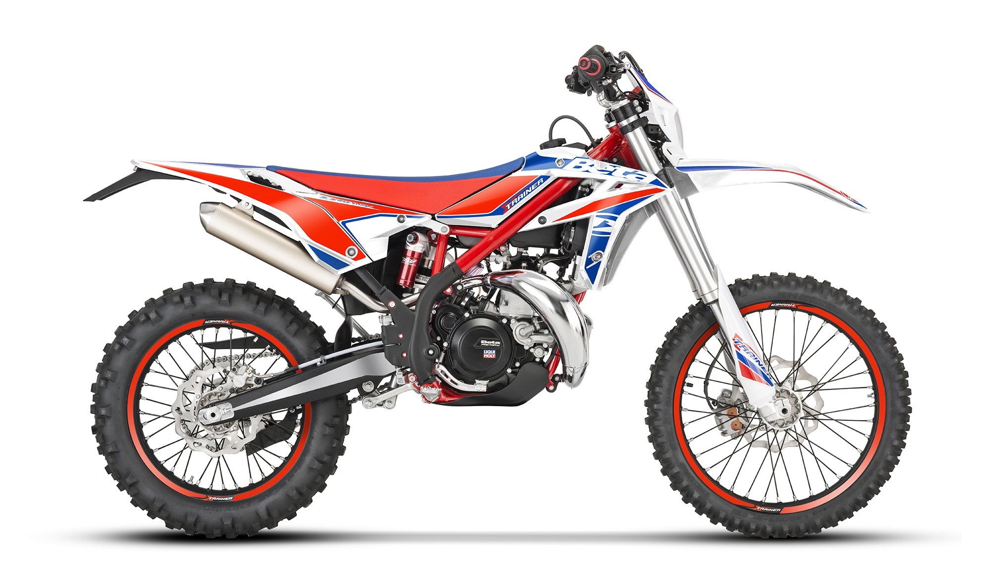
XTrainer даёт возможность райдеру даже низкого уровня проезжать эндуро трассы не перенапрягаясь физически. Характеристики мотоцикла делают его чрезвычайно универсальной моделью, созданной для того, чтобы любой получил максимум удовольствия!
Версия 2022 года получила несколько значительных обновлений и улучшений, чтобы подчеркнуть сильные стороны этой модели.
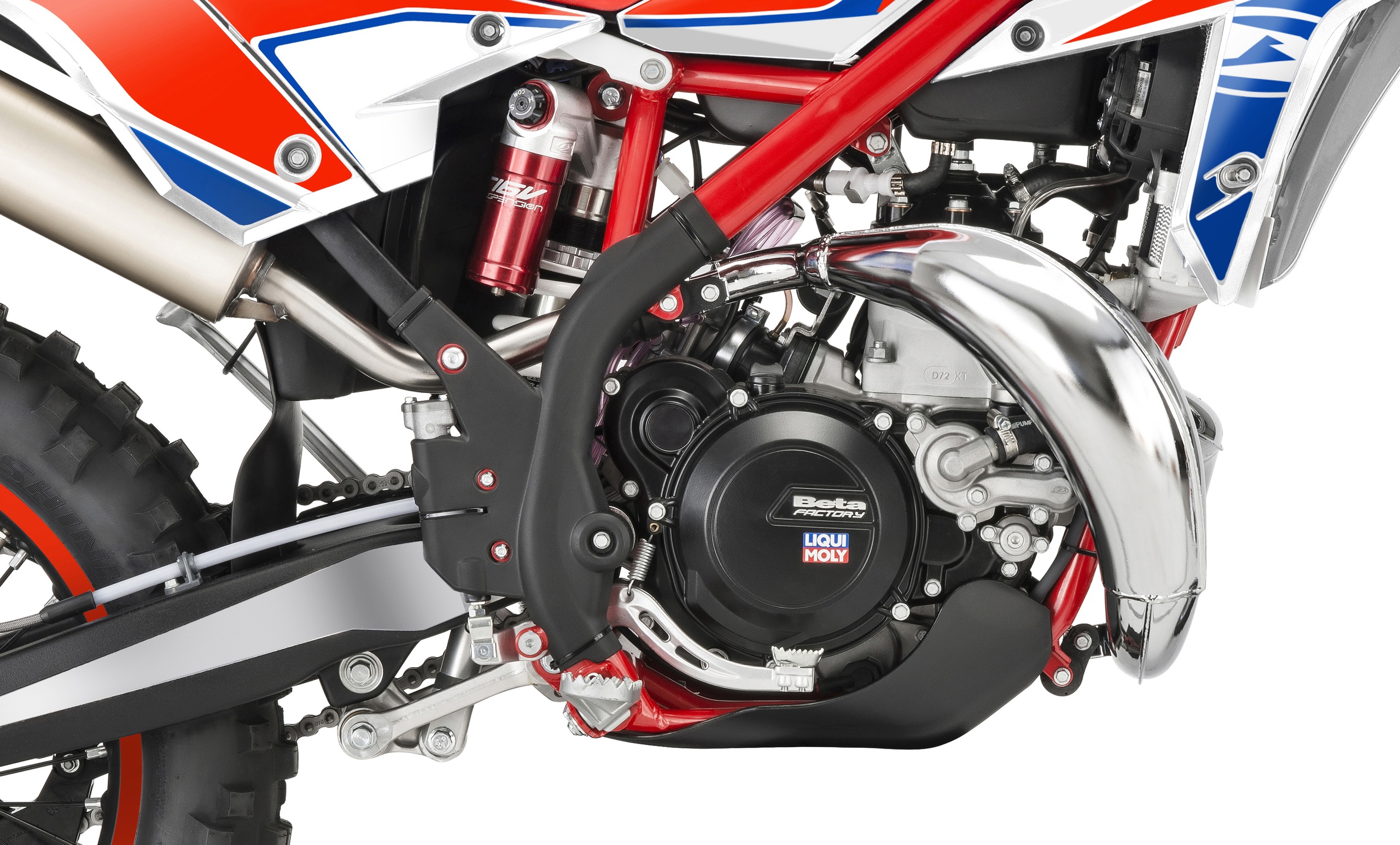
Новое в версии 300 кубов:
• Двигатель полностью переработан• Цилиндр большего диаметра• Поршень• Шатун короче• Головка блока цилиндров
Новой карта блока управления двигателем даёт более прогрессивный отклик на газ и более линейное распределение мощности. Мотоцикл целом стал ещё проще в управлении, обеспечивая более плавный стиль катания.
Общие изменения для XTrainer 250 и 300:
• Сцепление с мембранными пружинами (переключение легче, значительно уменьшает усталость от вождения, муфта способна передавать больший крутящий момент)• Обновлён стартер (более выносливый, отлично запускает двигатель даже в экстремальных условиях)• Переделана электрика мотоцикла для большей надёжности • Новая графика
Начало производства: конец мая этого года.
- Manuals
- Brands
- Beta Motorcycles Manuals
- Motorcycle
- Xtrainer 300 2T 2020
- Owner’s manual
-
Contents
-
Table of Contents
-
Troubleshooting
-
Bookmarks
Related Manuals for Beta Motorcycles Xtrainer 300 2T 2020
Summary of Contents for Beta Motorcycles Xtrainer 300 2T 2020
-
Page 2
XTRAINER 300 2T Thanks for you preference, and have a good time! This hand- book contains the information you need to properly operate and maintain your motorcycle. The data, specifications and images shown in this manual does not constitute an engagement on the part of BETAMOTOR S.p.A. BETAMOTOR reserves the right to make any changes and improvements to its models at any mo- ment and without notice. -
Page 3
IMPORTANT We recommend you to check all the tightenings after the first one or two hours’ ride over rough ground. Special attention should be paid to the following parts: rear sprocket ensure that the footrests are properly fixed front/rear brake levers/calipers/discs check that the plastics are properly fastened engine bolts shock absorber bolts/swingarm… -
Page 4: Table Of Contents
CONTENTS Operating instructions …………….5 Symbols ………………..5 Riding safety ………………6 CHAPTER 1 GENERAL INFORMATION ……….7 Vehicle identification data …………… 8 Tools kit ………………..8 Familiarizing with the vehicle…………..9 Specifications ………………10 Electrical system ………………. 14 Bulbs ………………..16 Fuses ………………..
-
Page 5
Air filter ………………..50 Spark plug ………………51 Carburettor ………………52 Front brake………………54 Rear brake ………………57 Clutch control ………………60 Check and adjusting of steering play …………62 Front wheel ………………63 Fork ………………..64 Rear suspension leverage …………..64 Tyres……………….. -
Page 6: Operating Instructions
OPERATING INSTRUCTIONS The vehicle must be accompanied by: number-plate, registration document, tax disc and insurance. Any modifications of the engine or other parts are punishable by severe sanctions including the confiscation of the vehicle. To protect your safety and that of others, always drive carefully and with your helmet on and always keep low beams on.
-
Page 7: Riding Safety
RIDING SAFETY Observe the Highway Code. Always wear approved personal protective equipment. Always ride with the low beam on. Always keep the crash helmet visor clean. Avoid wearing garments with hanging ends. Do not keep sharp or brittle objects in your pockets while riding. Properly adjust the rearview mirrors.
-
Page 8: Chapter 1 General Information
CHAPTER 1 GENERAL INFORMATION CONTENTS Vehicle identification data …………… 8 Frame identification …………….8 Engine identification …………….8 Tools kit ………………..8 Familiarizing with the vehicle…………..9 Main parts: ………………9 Specifications ………………10 Weight ………………. 10 Dimensions ………………10 Tyres ………………..
-
Page 9: Vehicle Identification Data
VEHICLE IDENTIFICATION DATA FRAME IDENTIFICATION Frame identification data A are stamped on the right side of the steering head tube. M01_V0001 ENGINE IDENTIFICATION Engine identification data B are stamped in the area shown in the figure. TOOLS KIT The following items are supplied as stan- dard: operation, maintenance manual, tool kit and the cable adapter to connect the CAN socket to a scantool.
-
Page 10: Familiarizing With The Vehicle
FAMILIARIZING WITH THE VEHICLE MAIN PARTS: 1 — Fuel tank 10 — Lower bumper 17 — Rear side panel 2 — Tank cap (Bumper kit) 18 — Rear mudguard 3 — Silencer 11 — Saddle 4 — Rear shock absorber 12 — Engine 5 — Headlight 13 — Front mudguard…
-
Page 11: Specifications
SPECIFICATIONS WEIGHT Weight in running order with full fuel and optional ………….. 115 kg (front 55 Kg; rear 60 Kg) DIMENSIONS maximum length (with plate holder) ……….2270 mm maximum width …………….802 mm overall height …………….1245 mm wheelbase…………….. 1467 mm saddle height …………….
-
Page 12: Front Suspension
FRONT SUSPENSION Hydraulic fork USD (shafts Ø43 mm) Spring ………………..K 8 Oil type ….see table “Recommended lubricants and liquids”, page 16 Oil quantity ……………….500 ml Spring preload register …………completely open Rebound clicks (from completely closed) ……….12 Wheel travel…………….
-
Page 13: Engine
ENGINE Version XTRAINER 250 2T Europa XTRAINER 300 2T Europa XTRAINER 250 2T XTRAINER 300 2T Type Single-cylinder, 2-stroke, liquid cooled and electric start 66,4 x 72 72 x 72 Bore x stroke [mm] Displacement [cm³] 293,1 Compression ratio 13,5:1 11,4:1 [g/km] * # Fuel consumption [l/100km] * #…
-
Page 14
Gearchange Version XTRAINER 250 XTRAINER XTRAINER 300 XTRAINER 2T Europa 250 2T 2T Europa 300 2T Primary drive 27/72 27/72 27/72 27/72 Gear ratio 1 gear 12/31 12/31 12/31 12/31 Gear ratio 2 gear 15/28 15/28 15/28 15/28 Gear ratio 3 gear 19/28 19/28… -
Page 15: Electrical System
ELECTRICAL SYSTEM ELECTRICAL DIAGRAM Key to colours Bi = White Ve = Green Ma = Brown Vi = Purple Bl = Blue Ne = Black Gi = Yellow Rs = Red Ar = Orange Az = Sky-blue Ro = Pink Gr = Grey…
-
Page 16: Electrical Diagram
LEGEND ELECTRICAL DIAGRAM 1) RIGHT HAND FRONT TURN INDICATOR 12V 6W 2) FRONT BRAKE LIGHT SWITCH 3) ENGINE STOP PUSH-BUTTON 4) ENGINE START PUSH-BUTTON 5) MAP SWITCH 6) WHEEL REVOLUTION SENSOR 7) ADJUST PUSH-BUTTON
 OIL MIX SYSTEM DIAGNOSIS WARNING LIGHT 9) RIGHT TURN INDICATORS WARNING LIGHT 10) DASHBOARD 11) HEADLIGHT TELL TALE LAMP…
 -
Page 17: Bulbs
BULBS High beam/low beam ……….HS1 12V — 35/35W Parking/daytime …………..12V — W5W Turn indicators ……………. 12V — H6W FUSES Two, one of them spare …………..10A…
-
Page 18: Recommended Lubricants And Liquid
Oil Recommendations RR & Xtrainer 2 Stroke Models: (Models WITH Oil Injection) Injection Oil: Motul 710 Transmission Oil Motul Transoil Expert 10w40 Brake Fluid Motul RBF 600 Coolant/Antifreeze Motul Motocool Expert Fork Oil Motul Factory Line 5 wt. Air Filter Oil Motul Air Filter Oil Air Filter Cleaner Motul Air Filter Clean…
-
Page 19: Chapter 2 Operation
CHAPTER 2 OPERATION CONTENTS Main parts ………………18 Fuel tank cap ……………… 18 Fuel cock ………………18 Starter ……………….. 19 Mixer oil tank cap …………….19 Clutch lever ………………19 LH switch ………………20 RH switch ………………20 Front brake lever and gas control …………20 Gear change lever…………….
-
Page 20: Main Parts
MAIN PARTS FUEL TANK CAP To open the fuel tank cap, turn it anticlock- wise. To close the fuel tank cap, set it on the tank and screw it clockwise. M02_L0029 FUEL COCK Fuel cock has three positions: M02_L0028 OFF: fuel supply closed. Fuel cannot pass from the tank to the carburettor.
-
Page 21: Starter
STARTER The starter lever is located on the carbu- rettor. To operate the choke pull it upward. M02_L0018 MIXER OIL TANK CAP The mixer oil tank cap is located under the saddle To gain access remove the saddle (page 78). M02_L0001 To open the fuel tank cap turn it anticlock- wise.
-
Page 22: Lh Switch
LH SWITCH The dip and service switch is located on the left side of the handlebar and is com- posed as follows: 1 — Horn button; 2 — Dip switch: parking lights and high beam; parking lights and low beam; 3 — Flash-to-pass button;…
-
Page 23: Gear Change Lever
GEAR CHANGE LEVER Gear change lever is fitted to the left side of the engine. The positions corresponding to the different gears are shown in the figure. M02_V0001 BRAKE PEDAL Brake pedal is located in front of the right- hand footrest. The rear brake is operated by pressing down the pedal.
-
Page 24: Keys
If the vehicle is used off-road, the closed stand can be further fastened by means of rubber band. M02_V0006 KEYS The vehicle is supplied with two keys (one key and its spare). STEERING LOCK To activate the steering lock: — turn the handlebar counter-clockwise; — push the key and turn counter-clockwise;…
-
Page 25: Dashboard Operating Instructions
DASHBOARD OPERATING INSTRUCTIONS MAIN PARTS Time Clock: 12/24 MODE Stopwatch: According to setup distance to record the testing time. Speed Log: Average speed and max Speedometer speed record Display range: 0~360km/h (0~225 MPH) Display unit: km/h or MPH Battery Inner Battery Level: Display range: 4 levels.
-
Page 26: Warning Lights
WARNING LIGHTS 1 Headlight indicator The system activates the indicator in synchrony with the activation of the mains beams. 2 Turn indicator lights The system activates the indicator in synchrony with the activation of the turn indicators. 3 Mixer oil level indicator light If the warning light comes on, refuel as soon as possible.
-
Page 27: Battery Replacement
BATTERY REPLACEMENT Follow this procedure for proper installa- tion. The meter includes an internal battery (CR2032). This battery shall be replaced only when power runs out. For replacement remove the headlight mask. Remove the battery cover located behind the instrument and pull out the battery.
-
Page 28: Adjust Button Function Instruction
ADJUST BUTTON FUNCTION INSTRUCTION In main screen, press the Adjust button once to switch the function from odometer to trip. In main screen, you could hold pressing the Adjust button for 3 seconds to change the speed unit from km/h to mph and vice versa. Press the Adjust button to switch from trip A to trip B.
-
Page 29: Select Button Function Instruction
Press the Adjust button to switch from Hour Meter B back to the main screen. Press and hold the Adjust button for 3 seconds to reset the Hour Meter B. The main screen. SELECT BUTTON FUNCTION INSTRUCTION Press the Select button during main screen to switch from Clock to Stopwatch.
-
Page 30: To Enter The Setting Mode
TO ENTER THE SETTING MODE Adjust+SelectX3 function instruction In main screen, press down the Adjust+SelectX3 to enter the tire circum- ference and sensing point setting (for changing different size tire.) The tire circumference and sensor point setting. Press the Adjust button to enter the tire circumference setting.
-
Page 31
The clock (Hour) setting EX: You want to set the hour at 14. Press the Select button to choose the hour you want to set. NOTE: Setting range: 0~23 H. NOTE: The sequent of cursor movement: Hour>Ten-Digit of Minute>Single Digit of Minute EX. -
Page 32
Switch from Press Select button to switch to Engine Oil Light Mileage setting screen. Press Adjust button to enter the Engine Oil Light Mileage setting. Maintenance Light Mileage Setting Press the Select button to choose mainte- nance mileage ON or OFF. NOTE: Default:OFF If ON is chosen, press Adjust button to enter the maintenance mileage setting… -
Page 33
Backlight brightness Press the Select button to adjust the bright- ness of the backlight NOTE: Adjustable Range: 1 ~ 5 NOTE: Default: 5 Press the Adjust button to exist from the Backlight Brightness setting. From switch to screen. Press Adjust button to enter the mileage setting. -
Page 34: Checks Before And After Use
CHECKS BEFORE AND AFTER USE For safe driving and long vehicle life you should: 1 Check the integrity of the oil pipe connecting the intake manifold to the electronic dosing. 2 Check all fluid levels. 3 Check the correct operation of the brakes and brake pad wear (page 54). 4 Check pressure, general condition and thickness of tread (page 65).
-
Page 35: Refuelling
REFUELLING See page 16 for the fuel specifications. Fuel tank capacity is shown on page 10. To refuel open the tank cap (page 18). After refuelling, screw the cap back and tighten securely. WARNING The refuelling should be performed with the engine off. WARNING Fire hazard.
-
Page 36: Oil Mixer Refuelling
OIL MIXER REFUELLING To refuel open the tank cap (page 19). Fuel tank capacity is shown on page 10. After refuelling, screw the cap back and tighten securely. Use the oil indicated on page 16 in the “Recommended lubricants and liquids” table.
-
Page 37: Chapter 3 Adjustments
CHAPTER 3 ADJUSTMENTS CONTENTS Key to symbols………………36 Brakes ………………..36 Front brake ………………36 Rear brake ………………36 Clutch ………………..37 Adjustment of gas clearance …………..37 Adjusting the idle speed ……………. 37 Carburetor settings according to the working conditions ……. 38 Exhaust valve control adjustment …………
-
Page 38: Key To Symbols
KEY TO SYMBOLS Tightening torque Threadlocker Medium BRAKES FRONT BRAKE The front brake is disk type with hydraulic control. The home position of brake lever 2 can be adjusted by means of screw 1. M03_L0017 Warning! Once the adjustment has been made, tighten the locknut 1A.
-
Page 39: Clutch
CLUTCH The adjustment screw 1 allows adjustment of the distance of lever 2 from the knob. The empty run is recovered automatically. M02_L0020 ADJUSTMENT OF GAS CLEARANCE The throttle control cable should always have a 3-5 mm play. In addition, the idle speed should not change when the han- dlebars are fully rotated to the left or right.
-
Page 40: Carburetor Settings According To The Working Conditions
To properly adjust the idle speed, follow these steps: Tighten the air adjustment screw no. 2 fully and then loosen it up to the value described in the carburetor setting table (page 12) Warm the engine for approx. 5 minutes, until the operational temperature is attained. 2 clockwise, until idling starts diminishing.
-
Page 41
XTRAINER 250 2T Altitude Carburetor Ambient temperature (SLM) setting -20°C÷ -6°C÷ 6°C ÷ 16°C ÷ 25°C ÷ 37°C ÷ ÷-7°C 5°C 15°C 24°C 36°C 49°C -2°F ÷ 19°F ÷ 42°F ÷ 61°F ÷ 79°F ÷ 99°F ÷ 20°F 41°F 60°F 78°F 98°F 120°F… -
Page 42
XTRAINER 300 2T Altitude Carburetor Ambient temperature (SLM) setting -20°C -6°C÷ 6°C ÷ 16°C ÷ 25°C ÷ 37°C ÷ ÷-7°C 5°C 15°C 24°C 36°C 49°C -2°F ÷ 19°F ÷ 42°F ÷ 61°F ÷ 79°F ÷ 99°F ÷ 20°F 41°F 60°F 78°F 98°F 120°F… -
Page 43: Exhaust Valve Control Adjustment
EXHAUST VALVE CONTROL ADJUSTMENT The power valve may be adjusted to suit your riding preference. Turning the screw inward reduces the overall power delivery. Turning the screw outward increases the overall power delivery. M04_L0025 HANDLEBAR ADJUSTMENT U-BOLT POSITION ADJUSTMENT The lower bracket 1 can be mounted in correspondence of the holes nr.
-
Page 44: Adjusting Fork
Apply the handlebar. Apply the top u-bolt. Refit the screws 6. Tighten to the torque indicated. 25Nm ADJUSTMENT OF THE HANDLEBAR POSITION The handlebar can be adjusted by rotating it back and forth. To adjust the handlebar loosen screws 1. Position the handlebar according to re- quirements.
-
Page 45: Shock Absorber
SHOCK ABSORBER ADJUSTING THE REBOUND DAMPER Turn screw A to adjust the hydraulic re- bound damper. M03_L0008 For adjustment refer to the table on the side. Increase Decrease For standard setting, refer to page 11. braking effect braking effect ADJUSTING THE HYDRAULIC COMPRESSION DAMPER Turn knob A to adjust the hydraulic com- pression damper.
-
Page 46: Adjusting The Spring Preload
ADJUSTING THE SPRING PRELOAD To adjust the spring preload, use the pro- cedure described below: Loosen the locking dowel A. Turn the ring nut B until you reach the desired preload. Lock the locking dowel A. For standard setting, refer to page 11. Note: for movement of the rings use a specific sector key with square pin.
-
Page 47: Chapter 4 Checks And Maintenance
CHAPTER 4 CHECKS AND MAINTENANCE CONTENTS Key to symbols……………….46 Engine oil ………………..46 Check the level ………………46 Replacement ………………46 Liquid coolant ………………..47 Check the level ………………47 Replacement ………………48 Air filter ………………..50 Removing and installing air filter ………….50 Air filter cleaning — XTRAINER 250/300 2T ……….51 Spark plug ………………..51 Carburettor ………………..52 Draining the carburettor float chamber ………….52…
-
Page 48: Key To Symbols
KEY TO SYMBOLS Tightening torque Threadlocker Medium ENGINE OIL CHECK THE LEVEL Hold the vehicle upright. Position the drive on a flat base ensuring stability. Remove the inspection cap 1. The oil level must arrive to the lower edge of check hole. M04_L0001 Otherwise restore the oil level through plug 2.
-
Page 49: Liquid Coolant
— Unscrew filler plug 1 and drain plug 2. — Drain all the oil from the crankcase. — Place the cap 2 and tighten to specified torque. Pour in the quantity of liquid indicated on page 10. Use the oil indicated on page 16 in 15Nm the “Recommended lubricants and liquids”…
-
Page 50: Replacement
WARNING: Wear appropriate protective cloth- ing and protection gloves. Keep coolant out of reach of chil- dren. Avoid any direct contact of the cool- ant with skin, eyes or clothing. If this happens: — with the eyes, rinse immediately with plenty of water and seek medical advice;…
-
Page 51
— Unscrew drain screw 3. — Proceed to filling. — Reapply the loading cap and the bleed- ing screw. The amounts of liquid are shown on page Use the liquid indicated on page 16 in M04_L0086 the “Recommended lubricants and liquids” table. -
Page 52: Air Filter
AIR FILTER Check after every ride. REMOVING AND INSTALLING AIR FILTER To access the filter is necessary: Remove the saddle (page 78). Pull the cover air filter (page 79). M04_L0014 Release filter fastener 1. M04_L0016 Pull out air filter 2. WARNING: After every intervention, check that nothing has been left inside the…
-
Page 53: Spark Plug
AIR FILTER CLEANING — XTRAINER 250/300 2T EUROPA Blow the filter with compressed air. AIR FILTER CLEANING — XTRAINER 250/300 2T Thoroughly wash the filter with water and soap. Dry the filter. Wet the filter with filter oil and then remove the excess oil to prevent it from drip- ping.
-
Page 54: Carburettor
CARBURETTOR DRAINING THE CARBURETTOR FLOAT CHAMBER If the carburettor tank needs to be emptied, proceed as described. Remove the chain protection 1, close the tank tap and put a cloth under the carbu- rettor, so that you can collect the running out fuel.
-
Page 55: Checking The Float Level
WARNING: Risk of poisoning! Fuel is poisonous liquid and a health hazard. Wear appropriate protective cloth- ing and protection gloves. Fuel must not come into contact with the skin, eyes, and clothing. Do not breathe in the fuel vapours. If contact occurs with the eyes, rinse immediately with plenty of water and seek medical advice.
-
Page 56: Front Brake
FRONT BRAKE CHECK THE LEVEL OF THE FRONT BRAKE FLUID Check the level of the brake fluid through sight A. The level of the fluid should never fall below the mark in the sight. RESTORING THE LEVEL OF THE FRONT BRAKE FLUID To restore the level of the brake fluid, loosen M04_L0051 the two screws 1, lift cap 2 and add brake…
-
Page 57: Bleeding The Front Brake
BLEEDING THE FRONT BRAKE To bleed air from the front brake circuit, proceed as follows: Remove the rubber cap 1 from the valve 2. Open the sump cap. Place one end of a small transparent tube into the valve 2, and the other end inside a container.
-
Page 58: Front Brake Lining Control
FRONT BRAKE LINING CONTROL In order to verify the wear condition of front brake is enough to view the caliper from the bottom, where is possible to glimpse the brake lining tails which will have to show a brake of 2 mm in thickness. If the stratum is lesser let’s start replacing them.
-
Page 59: Rear Brake
REAR BRAKE CHECK THE LEVEL OF THE REAR BRAKE FLUID Check the level of the brake fluid through sight A. The level of the fluid should never fall below the mark in the sight. RESTORING THE LEVEL OF THE REAR BRAKE FLUID To restore the oil level, top up by means of oil filler cap 1.
-
Page 60: Bleeding The Rear Brake
BLEEDING THE REAR BRAKE To bleed air from the rear brake circuit, proceed as follows: Remove the rubber cap 1 from the valve 2. Open the sump cap. Place one end of a small transparent tube into the valve 2, and the other end inside a container.
-
Page 61: Rear Brake Lining Control
REAR BRAKE LINING CONTROL In order to verify the wear condition of rear brake is enough to view the caliper from above, where is possible to glimpse the brake lining tails which will have to show a brake of 2 mm in thickness. If the stratum is lesser let’s start replacing them.
-
Page 62: Clutch Control
CLUTCH CONTROL CHECK THE LEVEL To check the oil level in the clutch pump, first remove cover 2. Remove the two screws 1 and take off cover 1 together with the rubber bellows. With the clutch pump in a horizontal posi- tion, the level of the oil should be 5 mm below the upper rim.
-
Page 63: Bleeding
BLEEDING To bleed air from the clutch pump, proceed as follows: Remove the rubber cap 1 from the valve 2. Open the sump cap. Place one end of a small transparent tube into the valve 2, and the other end inside a container.
-
Page 64: Check And Adjusting Of Steering Play
CHECK AND ADJUSTING OF STEERING PLAY Periodically check the play in the steering sleeve by moving the fork back and forth as shown in the figure. Whenever you feel play, adjust as described below: — Loosen the screws 1 — Loosen the screw 2 — Reduce the play by turning nut 3 Tighten the screws to the prescribed torque values.
-
Page 65: Front Wheel
FRONT WHEEL TIGHTENING Following removal of the wheel: Compress and release the fork 3-4 times. Tighten the wheel bolt and the screws of the foot-leg. 20Nm 50Nm M04_L0018…
-
Page 66: Fork
FORK 17Nm To maintenance refer at an authorized service center Betamotor. To check the tightening torques see as shown in the figure. WARNING: Tightening of the screws should be carried out by adjusting the torque wrench to the stability torque with repeated tightening until stability torque has been achieved.
-
Page 67: Tyres
TYRES Only fit tyres approved by BETAMOTOR. Unsuitable tyres can adversely affect the road holding of the vehicle. and in off-road riding. CHAIN Checking the drive chain periodically to ensure longer chain life. Always keep it lubricated and clean of deposited dirt. Take special care in preventing the lubricant from coming into contact with the rear tyre or brake disc, otherwise the tyre grip and the action of the brake would be greatly reduced, making it very difficult to control the vehicle.
-
Page 68: Check For Chain Wear
Loosen counternuts A on either side of the fork. Turn adjusting screws B on either side until the desired chain tension is obtained. Tighten counternuts A on either side of the fork. M04_L0061 Tighten the pin 1 to the torque indicated. 130Nm M04_L0060 CHECK FOR CHAIN WEAR…
-
Page 69: Headlight
HEADLIGHT Keep the headlight glass clean at all times (see page 71). Periodically check the correct angle of the light beam. REPLACING THE HEADLIGHT BULBS To remove the headlamp mask (page 80). For the replacement of the day light/ position light 1 remove the lamp from the lamp holder and replace it with a new one (page 16 for the lamp type).
-
Page 70: Tail Light
TAIL LIGHT Keep the tail light glass clean at all times (see page 71). The LED tail light is sealed. In the case of burnout of one or more LEDs it is necessary to replace the entire group. To replace, contact authorised Betamotor customer service.
-
Page 71: Inactivity
Even though the battery is sealed, there is a possibility that explosive gases may leak out. Keep sparks and open flames away from he battery. Keep spent batteries out of the reach of children and dispose of them as prescribed by law.
-
Page 72: Fuses
FUSES To access the fuse, remove the saddle (page 78). In the case of blown fuse, the vehicle will not start/stop: Three spare fuses comes with the kit ac- companying the vehicle. A blown fuse should only be replaced with M02_L0001 another of the same type.
-
Page 73: Cleaning The Vehicle
CLEANING THE VEHICLE GENERAL PRECAUTIONS WARNING: Do not clean your vehicle with a high-pressure device with a strong jet of water. Excessive pressure can reach electrical components, con- nectors, flexible cables, bearings, etc and can damage or destroy them. WARNING: Wash motorbikes frequently with cold water that are used near the sea (salty air) and on roads subject to salt spreading in winter.
-
Page 74: Electrical Connector Maintenance
ELECTRICAL CONNECTOR MAINTENANCE Disconnect the connectors listed below, blow compressed air on the connector both on the system and on the component side, and treat electrical contacts and switches with spray for electrical contacts. CONTROL UNIT CONNECTOR The connector location is shown in figure. To access the control unit connector it is necessary to remove the air filter cover panel (page 79).
-
Page 75: Prolonged Inactivity
PROLONGED INACTIVITY A few simple operations should be performed to keep the vehicle in good condition whenever it is to remain inactive for a long period (e.g. during the winter): Thoroughly clean the vehicle. Reduce the tyre pressures by approximately 30 percent, and if possible raise the tyres off the ground.
-
Page 76: Scheduled Maintenance Vehicle
SCHEDULED MAINTENANCE VEHICLE Engine Gear and clutch oil Spark plug Head screws Engine clamping screws * Kick start and gearchange lever screws Spark plug cap Coated clutch disks Clutch springs length Clutch/bell hub Gearbox bearing (drive shaft side) Cylinder Piston and segments Connecting rod Drive shaft bearings Surface appearance of the gearbox…
-
Page 77
Brakes Liquid level, pads thickness Disc thickness Pipe tightness Idle travel levers and drives sliding Cycling Shock absorber and telescopic fork Rear suspension linkage Fork cover Bearings of stearing Bolts Wheels Wheel spokes and rim coaxiality Tyres (wear and pressure) Bearings clearance Check (Clean, adjust, lubricate, replace as necessary) Replace/renew… -
Page 78: Tightening Torque Overview
TIGHTENING TORQUE OVERVIEW Here below is an overview of the tightening torque of all pieces subject to adjust- ment or maintenance: Forecarriage Tightening torque [Nm] Threadlock Wheel pin Fork foots — wheel pin Cavallotto parastelo sinistro Steering head base — fork legs Steering head — fork legs Stem pin on steering head Lower handlebar u-bolt — steering head…
-
Page 79: Chapter 5 Replacements
CHAPTER 5 REPLACEMENTS CONTENTS Removal and refitting of the saddle…………78 Removing and installing air filter cover panel ……….. 79 Removing and installing the headlamp mask ……….. 80…
-
Page 80: Removal And Refitting Of The Saddle
REMOVAL AND REFITTING OF THE SADDLE Press button 1. Remove the saddle towards the rear of the motorcycle. To re-assemble insert the cavity 1 of the saddle in slot 2. Press the saddle down in the middle and at the same time, push it forwards until the bayonet joint engages in its seat.
-
Page 81: Removing And Installing Air Filter Cover Panel
WARNING Make sure the bayonet joint 3 is firmly inserted into the button lock. REMOVING AND INSTALLING AIR FILTER COVER PANEL Remove the saddle (page 78). Grab the side panel in the front side and pull out. To refit insert the tabs 1 into their slots. Slide the side panel toward the vehicle.
-
Page 82: Removing And Installing The Headlamp Mask
REMOVING AND INSTALLING THE HEADLAMP MASK Remove the screw 1. M05_L0012 Remove the jumper 2 by pulling the rear portion towards you and slide it towards the rear. M05_L0013 Unhook the elastics 3 (one on each side). M05_L0012 Pull the mask upwards and rotate it forward from the top.
-
Page 83: Chapter 6 Troubleshooting
CHAPTER 6 TROUBLESHOOTING CONTENTS Troubleshooting ………………. 82 Alphabetical index …………….83…
-
Page 84: Troubleshooting
TROUBLESHOOTING PROBLEM CAUSE REMEDY Engine does not start — Fuel system clogged (fuel lines, fuel Contact authorised BETAMOTOR tank, fuel cock) customer service — Air filter dirty Check the air filter — No current supplied to spark plug Clean or replace the spark plug. If the problem persists, contact authorised BETAMOTOR customer service — Engine flooded…
-
Page 85
ALPHABETICAL INDEX Adjusting fork ………………42 Adjusting the idle speed ……………. 37 Adjustment of gas clearance …………..37 Air filter ………………..50 Battery ………………..68 Brakes ………………..36 Bulbs ………………..16 Carburettor ………………52 Chain ………………..65 Check and adjusting of steering play …………62 Checks before and after use ………….. -
Page 86
Liquid coolant ………………47 Main parts ………………18 Oil mixer refuelling …………….34 Operating instructions …………….5 Prolonged inactivity …………….73 Rear brake ………………57 Rear suspension leverage …………..64 Recommended lubricants and liquid …………16 Refuelling ……………….. 33 Removal and refitting of the saddle…………78 Removing and installing air filter cover panel ………..
 OIL MIX SYSTEM DIAGNOSIS WARNING LIGHT 9) RIGHT TURN INDICATORS WARNING LIGHT 10) DASHBOARD 11) HEADLIGHT TELL TALE LAMP…
 - Home
- Brands
- Beta
- Motorcycle
- X-Trainer 300 2T
- Operation & User’s Manual
Manual for Beta X-Trainer 300 2T Motorcycle (76 pages)
Specifications:
|
Beta X-Trainer 300 2T: Read PDF Manual Online
Accompanying Data:
Beta X-Trainer 300 2T Motorcycle PDF Operation & User’s Manual (Updated: Friday 31st of March 2023 05:29:44 AM)
Rating: 4.6 (rated by 24 users)
Compatible devices: RR 50 cc ENDURO, RE 125, RR 390, REV 3, RR 400, 250-300 RR, RR 4T-250, EVO 4T.
Recommended Documentation:
Beta X-Trainer 300 2T: Text of Operation & User’s Manual
(Ocr-Read Version Summary of Contents, UPD: 31 March 2023)
-
52, 4 CHECKS AND MAINTENANCE 52 GB BLEEDING THE REAR BRAKE To bleed air from the rear brake circuit, proceed as follows: •Remove the rubber cap 1 from the valve 2. •Open the sump cap. •Place one end of a small transparent tube into the valve 2, and the other end inside a container. •Pump with the brake lever 2/3 times and keep the pedal pressed. •Unscrew t…
-
15, 1 GENERAL INFORMATION 15 GB LEGEND ELECTRICAL DIAGRAM 1) RIGHT-HAND FRONT TURN INDICATOR 12V 6W 2) FRONT BRAKE LIGHT BUTTON 3) START BUTTON 4) WHEEL REVOLUTION SENSOR 5) TURN INDICATORS WARNING LIGHT 6) OIL RESERVE WARNING LIGHT 7) DASHBOARD
HEADLIGHT TELL TALE LAMP 9) MIXER DIAGNOSIS WARNING LIGHT 10) ENGINE STOP BUTTON 11) HORN BUTTON 12) HE… -
75, INDEX 75 GB ALPHABETICAL INDEX Adjusting fork …………………………………………………………………………..36 Adjustment of gas clearance …………………………………………………………35 Air fi lter ………………………………………………………………………………….44 Battery ………………..…
-
2, 2 GB IMPORTANT We recommend you to check all the tightenings after the fi rst one or two hours’ ride over rough ground. Special attention should be paid to the following parts: • rear sprocket • ensure that the footrests are properly fi xed • front/rear brake levers/calipers/discs • check that the plastics are properly fastened • engine bolts • shock absorber bolts/…
-
25, 2 OPERATION 25 GB 2.1 SETUP SEQUENCE Select unit of measure Wheel size Clock format Setting the Time Maintenance reminder 2.1.1 Selecting the unit of measure (Km/h or M/h): TO SELECT THE UNIT OF MEASURE (Km/h or M/h), PRESS THE RIGHT OR LEFT BUTTON. WAIT 5 SECONDS TO PROCEED TO THE NEXT SETTING. DO NOT PRESS ANY BUTTONS. 2.1.2 Selecting the wheel size (rolling circumference): The instrument…
-
51, 4 CHECKS AND MAINTENANCE 51 GB A 1 REAR BRAKE CHECK THE LEVEL OF THE REAR BRAKE FLUID Check the level of the brake fl uid through sight A. The level of the fl uid should never fall below the mark in the sight. RESTORING THE LEVEL OF THE REAR BRAKE FLUID To restore the oil level, top up by means of oil fi ller cap 1. Use the liquid indicated on page 16…
-
56, 4 CHECKS AND MAINTENANCE 56 GB CHECK AND ADJUSTING OF STEERING PLAY Periodically check the play in the steering sleeve by moving the fork back and forth as shown in the fi gure. Whenever you feel play, adjust as described below: — Loosen the screws 1 — Loosen the screw 2 — Reduce the play by turning nut 3 Tighten the screws to the prescribed torque valu…
-
67, 4 CHECKS AND MAINTENANCE 67 GB SCHEDULED MAINTENANCE VEHICLE Key C Check (Clean, adjust, lubricate, replace as necessary) S Replace/renew R Adjust P Clean T Tighten End of running-in — 3 hours Coupon 1 — 30 hours Coupon 2 — 60 hours Coupon 3 — 90 hours Coupon 4 — 120 hours Coupon 5 — 150 hours Coupon 6 — 180 hours Engine Gear and clutch oil SSSSSSS Spark plug CSSS He…
-
27, 2 OPERATION 27 GB 5 SPEEDOMETER Speed The speed is displayed in the centre of screens 1 or 2 and can range from 0 to 399.9 km/h or M/h. The unit of measure (km/h or M/h) appears next to the speed reading. Maximum (Max) and Average (AVG) speed The Maximum (MAX) or Average (AVG) speeds are displayed on screen 3 to the left of the display. The instrument automatically update…
-
28, 2 OPERATION 28 GB Travelled distance (DST) The travelled distance can range from 0 to 9999.9 miles or kilometers and appears on the right side of screen 1. To clear the travelled distance, hold the right button down for 5 seconds. Note: you must be on screen 1 to clear the travelled distance. Travelled distance 2 (DST 2) Travelled distance 2 can range from 0 to 9999.9…
-
11, 1 GENERAL INFORMATION 11 GB FRONT SUSPENSION Hydraulic fork USD (shafts Ø43 mm) Spring …………………………………………………………………………………..K 8 Oil type …………… see table “Recommended lubricants and liquids”, page 16 Oil quantity ………………………………………………………………………
-
62, 4 CHECKS AND MAINTENANCE 62 GB BATTERY Battery is located under the saddle and requires no maintenance. Keep the battery terminals clean. If neces- sary, protect them with a thin fi lm of acid- free grease. BATTERY REMOVAL AND ASSEMBLY Remove the saddle (page 70). Release the rubber band. FIRST disconnect the negative connector (black) from negative (-) pole and THEN positive conne…
-
3, CONTENTS 3 GB CONTENTS Operating instructions …………………………………………………………………..5 Ecologic guide ……………………………………………………………………………5 Riding safety ……………………………………………………………………………..6 CHAPTER 1 GENERAL INFORMATION ……………………
-
73, 6 TROUBLESHOOTING 73 GB CHAPTER 6 TROUBLESHOOTING CONTENTS Troubleshooting ………………………………………………………………………..74 Alphabetical index …………………………………………………………………….75
…
DOC-cd96b87e:
Beta X-Trainer 300 2T: Recommended Instructions
UC 148 Aut, himw 64223 s, WL218-sw, DEH-P9800BT — Radio / CD, FES388WGC, EXES-6000


-
INSTRUCTION MANUALWARRANTYThunder Tiger Corporation guarantees this model kit to be free from defects in both material and workmanship.The total monetary value under warranty will in no case exceed the cost of the original kit purchased. This warrantydoes not cover any components damaged by use or modification. Part or parts missing from this kit must bereported within 60 days of purchase. No …
999R 16
-
BMW MotorradR 1200 R bmw-motorrad.comThe Ultimate Riding MachineEngineType . . . . . . . . . . . . . . . . . . . . . . . . . Air/oil-cooled flat twin (‚Boxer‘) 4-stroke, one camshaft and four valves per cylinder, central balancer shaftBore / stroke . . . . . . . . . . . . . . . . . .101 mm x 73 mmCapacity . . . . . . . . . . . . . . . . . . . . .1,170 ccRated output . . . . . . . . . . . …
K 1200 R — 1
-
This manual should be considered a permanent part of themotorcycle and should remain with the motorcycle when it is resold.This publication includes the latest production information availablebefore printing. Honda Motor Co., Ltd. reserves the right to makechanges at any time without notice and without incurring anyobligation.No part of this publication may be reproduced without writtenpermissi …
CBF125NA 2018 141
-
PrefaceWarning/Caution Read this book and keep firmly in mind the essentials. We use words such as “Warning”or “Caution” for differentiating the importance of issues need be paid attention to, please carefully comprehend their exact definition.Warning — This word indicates the issues involved personal safety of driver, neglect of this issue may lead to injury.Caution � …
LX250GY-3 36
-
BEDIENUNGSANLEITUNGOWNER’S HANDBOOKMANUALE D’USOMANUEL D’UTILISATIONMANUAL DE INSTRUCCIONESART. NR. 3.205.247.97125/200250/300/380SX/MXC/EXC/EGS’98’98BEDIENUNGSANLEITUNGOWNER’S HANDBOOKART. NR. 3.205.247.97125/200/250/300/300/380 SX/MXC/EXC/EGS …
1998 125sx 39
-
SafetyFirstSafeOperatingRulesMotorcyclesaredifferentfromothervehicles.Theyoperate,steer,handleandbrakedifferently.Unskilledorimproperusecouldresultinlossofcontrol,deathorseriousinjury.(00556c)Takearidertrainingcourse.Readowner’smanualbeforeriding,addingaccessoriesorservicing …
DYNA STREET BOB 139
-
MOTO GUZZI WOULD LIKE TO THANK YOUfor choosing one of its products. We have drawn up this manual to provide a comprehensive overview of your vehicle’s quality features. Please read itcarefully before riding the motorcycle for the first time. It contains information, tips and precautions for using your vehicle. It also describes features,details and devices to assure you that you …
V7 Racer 205
-
99011-06J52-01AVL1500B/T/BTPrinted in JapanPart No. 99011-06J52-01A December, 2014 ENVL1500B/T/BTOWNER’S MANUALL5TK C© COPYRIGHT SUZUKI MOTOR CORPORATION 2014CyanMagentaYellowBlack8 mmVL1500B/T/BT (99011-06J52-01A)4/1To p1st cover4th cover …
Intruder VL1500B 191
-
Periodical Maintenance Chart Item First month Every month Every 3 months Every 6 months Every 1 year Note 1 Motor I 2 Motor Controller I 5 Battery I I 6 Charger I I 7 DC to DC Converter I I 8 Tire I I 9 Tire Pressure I I 10 Brake Clearance I I A 11 Light / Electrical System / Meter I I 12 Electri …
e-Virid 28
-
Dear Customer,Congratulations! Over one crore Indians are part of the TVS XL family and now, it gives us great pleasure to welcome you to it. We hope you have a great journey ahead just as millions of satisfied TVS customers have. With stringent quality checks, great attention and care has been taken to ensure that your TVS XL 100 is in a perfect operating condi …
XL Series 44
Additional Information:
Popular Right Now:
Operating Impressions, Questions and Answers:
мы и наши партнеры используем файлы cookie для отображения персонализированной рекламы, а также для профилирования и измерения. Вы согласны?
OK
NO
Cookie policy
- Мотоциклы
- Beta
:
: Xtrainer

Beta Xtrainer
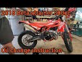
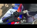
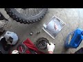
Как заменить моторное масло на Beta Xtrainer?
Замена моторного масла на Beta Xtrainer выполняется путем ослабления пробки слива масла из …читать все…
Опубликовано 9 Апрель 2023 by ScegliAuto

Beta Xtrainer
Как заменить задний амортизатор Beta Xtrainer?
Для замены заднего амортизатора Beta Xtrainer необходимо ослабить винты крепления боковых …читать все…
Опубликовано 25 Ноябрь 2022 by ScegliAuto

Beta Xtrainer
Как заменить рычаг сцепления Beta XTrainer?
Для замены рычага сцепления Beta XTrainer необходимо ослабить два винта, которые крепят сам …читать все…
Опубликовано 19 Сентябрь 2022 by ScegliAuto
Beta Xtrainer
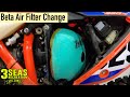
Как заменить воздушный фильтр на Beta Xtrainer?
Чтобы заменить воздушный фильтр Beta Xtrainer, вам необходимо снять левую боковую панель, …читать все…
Опубликовано 10 Июль 2022 by ScegliAuto
Beta Xtrainer
Как заменить поршень Beta Xtrainer?
Чтобы заменить поршень Beta Xtrainer, вам нужно получить доступ к верхней части двигателя, …читать все…
Опубликовано 26 Май 2022 by ScegliAuto
Beta Xtrainer
Как заменить моторное масло Beta Xtrainer 300?
Чтобы заменить моторное масло Beta Xtrainer 300, вам необходимо ослабить винты, которые крепят …читать все…
Опубликовано 14 Май 2022 by ScegliAuto
Beta Xtrainer
Как заменить рычаг сцепления Beta XTrainer?
Замена рычага сцепления Beta XTrainer осуществляется путем ослабления винта, …читать все…
Опубликовано 8 Апрель 2022 by ScegliAuto
Beta Xtrainer
Как заменить карбюратор Beta Xtrainer?
Чтобы заменить карбюратор Beta Xtrainer, вы должны сначала ослабить все винты, которые …читать все…
Опубликовано 7 Декабрь 2021 by ScegliAuto

Beta Xtrainer
Как заменить поршень Beta Xtrainer 300?
Чтобы заменить поршень Beta Xtrainer, вы должны сначала открыть корпус водяного насоса и …читать все…
Опубликовано 27 Ноябрь 2021 by ScegliAuto

Beta Xtrainer
Как заменить прокладку водяного насоса Beta Xtrainer?
Чтобы заменить прокладку водяного насоса Beta Xtrainer, необходимо сначала открыть пробку …читать все…
Опубликовано 23 Ноябрь 2021 by ScegliAuto
Beta Xtrainer
Как заменить сцепление Beta XTrainer?
Для замены сцепления Beta XTrainer необходимо ослабить все винты, крепящие защитный кожух …читать все…
Опубликовано 23 Октябрь 2021 by ScegliAuto

Beta Xtrainer
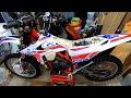
Как заменить сцепление Beta XTrainer?
Для замены сцепления Beta XTrainer удобно положить велосипед на бок, как показано на видео. …читать все…
Опубликовано 22 Октябрь 2021 by ScegliAuto
Амортизаторы (1)
Карбюратор (1)
проверки и техническое обслуживание (2)
Воздушный фильтр (1)
Сцепление (2)
(2)
Моторное масло (2)
Насос (1)
Установка багажных реек.
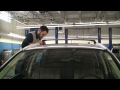
Автомобиль уже имеет предрасположенность для установки багажника, поэтому необходимо приобрести подходящие для модели автомобиля багажные рейли. В качестве первой операции необходимо удалить восемь пластиковых заглушек, скрывающих резьбовую гайку. Расположите две балки на крыше в соответствии с отверстиями для крепления, затем закрутите восемь крепежных винтов, не затягивая их. Теперь можно осторожно затянуть винты, повторно проверив, чтобы все они были правильно закручены. Хорошей практикой является не перегружать багажник и поддерживать размеры в пределах законных ограничений.
Смотрите видео!
by ScegliAuto
больше видео
- Как сбросить лампочку AdBlue на Peugeot 3008 1.5 BlueHDi
Опубликовано 21 Декабрь 2022 by ScegliAuto
- Как открыть лючок бензобака на Рено Каптур?
Опубликовано 13 Декабрь 2022 by ScegliAuto
- Как настроить время Фольксваген Гольф 8
Опубликовано 8 Декабрь 2022 by ScegliAuto
- Как изменить время на Iveco Daily
Опубликовано 19 Ноябрь 2022 by ScegliAuto
- Почему загорается лампочка Check Engine?
Опубликовано 18 Ноябрь 2022 by ScegliAuto
- Где находится управление противотуманными фарами в Citroen C3 Aircross?
Опубликовано 14 Ноябрь 2022 by ScegliAuto
- Как изменить время на Citroen C5 Aircross
Опубликовано 10 Ноябрь 2022 by ScegliAuto
- Как изменить время в Toyota Yaris Cross
Опубликовано 9 Ноябрь 2022 by ScegliAuto
- Где находится инерционный переключатель в Fiat Punto?
Опубликовано 8 Ноябрь 2022 by ScegliAuto
- Как перезагрузить дисплей на Пежо 208?
Опубликовано 8 Ноябрь 2022 by ScegliAuto