- Manuals
- Brands
- Deif Manuals
- Controller
- AGC 150
- Operator’s manual
-
Contents
-
Table of Contents
-
Bookmarks
Quick Links
OPERATOR’s MANUAL
AGC 150
4189341186E
Related Manuals for Deif AGC 150
Summary of Contents for Deif AGC 150
-
Page 1
OPERATOR’s MANUAL AGC 150 4189341186E… -
Page 2: Table Of Contents
1. Introduction 1.1 About the operator’s manual ………………………………… 1.2 Warnings and safety ……………………………………1.3 Legal information ……………………………………..2. Controller overview 2.1 Overview of buttons and LEDs ………………………………..2.1.1 Display overview ……………………………………2.1.2 Display settings ……………………………………. 2.2 Controller types ……………………………………..2.2.1 Genset controller layouts ………………………………….
-
Page 3: Introduction 1.1 About The Operator’s Manual
The general purpose of this document is to give the operator important information to be used in the daily operation of the controller. DANGER! Read this document before working with the AGC 150 controller. Failure to do this may result in human injury or damage to the equipment.
-
Page 4: Warnings And Safety
Warranty CAUTION The AGC 150 controller is not to be opened by unauthorised personnel. If opened anyway, the warranty will be lost. Disclaimer DEIF A/S reserves the right to change any of the contents of this document without prior notice.
-
Page 5: Controller Overview
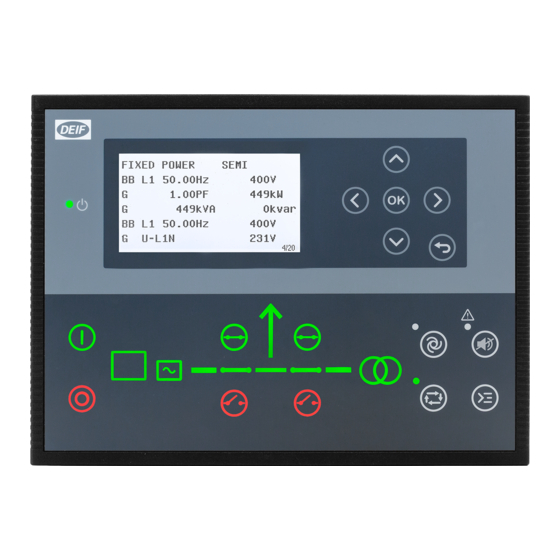
2. Controller overview Overview of buttons and LEDs 2.1.1 Front overview Name Function Green: The controller power is ON. Power ON OFF: The controller power is OFF. Resolution: 240 x 128 px. Display screen Viewing area: 88.50 x 51.40 mm. Six lines, each with 25 characters.
-
Page 6: Display Settings
Name Function Green: Breaker is ON. Breaker symbols Green flashing: Synchronising or de-loading. Red: Breaker failure. Green: Generator voltage and frequency are OK. The controller can synchronise and close the breaker. Generator Green flashing: The generator voltage and frequency are OK, but the V&Hz OK timer is still running. The controller cannot close the breaker.
-
Page 7: Controller Types
Controller types 2.2.1 Genset controller layouts Single genset controller in Island mode 1. Power ON 2. Display screen (monochrome) 3. Navigation 4. OK 5. Back 6. AUTO mode 7. Silence horn 8. Short cut menu for commands 9. SEMI-AUTO mode 10.
-
Page 8
Single genset controller in parallel without mains breaker 1. Power ON 2. Display screen (monochrome) 3. Navigation 4. OK 5. Back 6. AUTO mode 7. Silence horn 8. Short cut menu for commands 9. SEMI-AUTO mode 10. Mains symbol 11. Close breaker 12. -
Page 9: Mains Controller Layouts
2.2.2 Mains controller layouts Mains controller 1. Power ON 2. Display screen (monochrome) 3. Navigation 4. OK 5. Back 6. AUTO mode 7. Silence horn 8. Short cut menu for commands 9. SEMI-AUTO mode 10. Mains symbol 11. Close breaker 12.
-
Page 10: Bus Tie Breaker Controller Layouts
2.2.3 Bus tie breaker controller layouts Bus tie braker controller 1. Power ON 2. Display screen (monochrome) 3. Navigation 4. OK 5. Back 6. AUTO mode 7. Silence horn 8. Short cut menu for commands 9. SEMI-AUTO mode 10. — 11.
-
Page 11: Hybrid Controller Layouts
2.2.5 Hybrid controller layouts Single genset controller in Island mode 1. Power ON 2. Display screen (monochrome) 3. Navigation 4. OK 5. Back 6. AUTO mode 7. Silence horn 8. Short cut menu for commands 9. SEMI-AUTO mode 10. — 11.
-
Page 12: Mimic Function
2.2.6 Mimic function With the Mimic function the operator can choose how the control buttons and LED’s are shown on AGC 150, and thereby get a better overview of the controller in different applications. Configure the Mimic function under Settings > Basic settings > Controller settings > Display > LED mimic.
-
Page 13
Guided Active control buttons and LED’s are visible, inactive are not shown. Example: AGC 150 is in SEMI-AUTO mode. The generator is stopped. The only possible action is to start the generator, and so only the Start button is visible. -
Page 14: Running Modes
3. Running modes Mode overview AGC 150 has four different running modes and one block mode: • AUTO: In AUTO mode, the controller will operate automatically, and the operator cannot initiate any sequences manually. • SEMI-AUTO: In SEMI-AUTO mode, the operator has to initiate all sequences. This can be done via the push-button functions, Modbus commands or digital inputs.
-
Page 15: Menu Structure
The View menu When AGC 150 is powered up, the View menu appears. It is the daily use menu for the operator, which shows various measured values. If an alarm is present, the event and alarm list is shown at power-up.
-
Page 16: Status Line Texts
Status line texts Status text Condition Comment BLOCK Block mode is activated. SIMPLE TEST LOAD TEST Test mode is activated. FULL TEST SIMPLE TEST ###.#min Test mode is activated and test timer LOAD TEST ###.#min counting down. FULL TEST ###.#min ISLAND MAN Genset stopped or running and no other action taking place.
-
Page 17
Status text Condition Comment Genset running in mains power export MPE ACTIVE mode. Generator stopped and active alarm(s) on DG BLOCKED FOR START the generator. Generator running, GB open and an GB ON BLOCKED active Trip GB alarm. SHUTDOWN OVERRIDE The configurable input is active. -
Page 18: Texts Only Related To Power Management
Condition Comment Broadcasts one of the four applications Broadcast of an application through the BROADCASTING APPL. # from one AGC 150 to the other controllers CAN line. in the power management system. RECEIVING APPL. # Receiving an application. BROADCAST COMPLETED Successful broadcast of an application.
-
Page 19
Comment The new controller is being added to the SETUP IN PROGRESS existing application. Successful update of the application in all SETUP COMPLETED AGC 150 controllers. Remove the power management CAN REMOVE CAN CONNECTOR lines. Table 4.2 DG controller Status text… -
Page 20: Default Display Views
Default display views Overview of the default display views 1 to 20. The display views are customisable via the Utility Software . Table 4.5 Display view 1 Line Generator Mains Hybrid Engine Drive U-Supply 0.0V U-Supply 0.0V U-Supply 0.0V PV OFF 0kvar 0kW U-Supply 0.0V G 0.00PF 0kW M 0.00PF 0kW…
-
Page 21
Line Generator Mains Hybrid Engine Drive G U-L3L1 0V M S 0kVA BA S 0kVA G U-L3L1 0V G U-Max 0V M 0 0 0V BA 0 0 0V G U-Max 0V G U-Min 0V M 0 0 0A BA 0 0 0A G U-Min 0V Table 4.10 Display view 6… -
Page 22
Table 4.14 Display view 10 Line Generator Mains Hybrid Engine Drive G U-L1N 0V M U-L1L2 0V Multi input 20 0.0V G U-L1N 0V G U-L2N 0V M U-L2L3 0V Multi input 21 0.0V G U-L2N 0V G U-L3N 0V M U-L3L1 0V Multi input 22 0.0V G U-L3N 0V… -
Page 23
Table 4.18 Display view 14 Line Generator Mains Hybrid Engine Drive Tgt 0kW 0% PV E total 0kWh Tgt 0kvar 0% [yyyy-mm-dd time] PV E year 0kWh Tgt 0.0 Hz 0.0 PV E month 0kWh Tgt 0V L-N 0V MB Operations 0 PV E week 0kWh kW 0% Q 0% TB Operations 0… -
Page 24: Available Display Texts
Table 4.22 Display view 18 Line Generator Mains Hybrid Engine Drive Multi input 20 0.0V Multi input 20 0.0V Multi input 21 0.0V Multi input 21 0.0V Multi input 22 0.0V Multi input 22 0.0V Multi input 23 0.0V Multi input 23 0.0V MPU 0rpm MPU 0rpm Table 4.23…
-
Page 25
Table 4.25 Analogue inputs Generator Mains Hybrid Engine Drive Multi input 20 0 Multi input 20 0 Multi input 20 0 Multi input 20 0 Multi input 20 0 Multi input 21 0 Multi input 21 0 Multi input 21 0 Multi input 21 0 Multi input 21 0 Multi input 22 0… -
Page 26
Generator Mains Hybrid Engine Drive Fan B pr. 0 0hrs Fan B pr. 0 0hrs Fan B pr. 0 0hrs Fan C pr. 0 0hrs Fan C pr. 0 0hrs Fan C pr. 0 0hrs Fan D pr. 0 0hrs Fan D pr. -
Page 27
Generator Mains Hybrid Engine Drive BB f-L2 0.00Hz BB f-L2 0.00Hz BB f-L2 0.00Hz BB f-L2 0.00Hz BB f-L3 0.00Hz BB f-L3 0.00Hz BB f-L3 0.00Hz BB f-L3 0.00Hz P BTB Ana21 0kW BB 0 0 0V BB 0 0 0V BB 0 0 0V BB 0 0 0V BB 0 0 0V… -
Page 28
Generator Mains Hybrid Engine Drive Energy Total 0kvarh Energy Total 0kvarh Energy Total 0kvarh Energy Total 0kvarh Energy Total 0kvarh Energy Week 0kWh Energy Week 0kWh Energy Week 0kWh Energy Week 0kWh Energy Week 0kWh Energy Week 0kvarh Energy Week 0kvarh Energy Week 0kvarh Energy Week 0kvarh Energy Week 0kvarh… -
Page 29
Generator Mains Hybrid Engine Drive G U-Max 0V M U-Max 0V BA U-Max 0V G U-Max 0V G U-Max 0V G U-Min 0V M U-Min 0V BA U-Min 0V G U-Min 0V G U-Min 0V Negative volt. 0.0% Negative volt. 0.0% Negative volt. -
Page 30
Generator Mains Hybrid Engine Drive PV curtailed energy, week PV curtailed energy, year PV P energy, day PV P energy, month PV P energy, total PV P energy, week PV P energy, year PV P reference PV Q energy, day PV Q energy, month PV Q energy, total PV Q energy, week… -
Page 31: The Settings Menu
The Settings menu The Settings menu is used for setting up the controller, and if the operator needs detailed information that is not available in the view menu system. Navigate through the different setup parameters with the Up , Down and OK buttons.
-
Page 32: The Service View
DG BLOCKED FOR START Service view Menu numbers In AGC 150 each setting or parameter has a unique menu number. On the display screen, the menu number can be seen in the upper right corner: DG BLOCKED FOR START Generator nom inal U…
-
Page 33: The Jump Function
To activate the Jump function in the Utility Software, select the Parameter page and then the Jump menu. 4.11 Engine Drive shortcut menu The AGC 150 has a shortcut menu for configuring the PID set points. To activate the Engine Drive shortcut menu, press the Shortcut button.
-
Page 34: Hybrid Shortcut Menu
• Not active during ramp up/down. 4.12 Hybrid shortcut menu The AGC 150 has a shortcut menu for start/stop of the PV inverter in SEMI-AUTO mode. To activate the Hybrid shortcut menu, press the Shortcut button. DG BLOCKED FOR START…
-
Page 35: Remote Display Local Menu
Gives you information about the software in the Remote display. 4.14 Exhaust after-treatment (Tier 4 Final/Stage V) AGC 150 supports Tier 4 Final/Stage V requirements, and provides monitoring and control of the exhaust after-treatment system, as requested by the standard.
-
Page 36
Item Symbol Notes Engine emission system failure Shows an emission failure or malfunction. Diesel Particle Filter (DPF) Shows that a regeneration is needed. Application mode Diesel Particle Filter (DPF) Inhibit Shows that regeneration is inhibited. High temperature — Regeneration Shows a high temperature and regeneration is in process. Engine interface status Shows an engine warning. -
Page 37: Alarm Handling And Log List
5. Alarm handling and log list Alarm handling If the function Alarm Jump is ON, the controller will automatically show the Alarm list on the display screen, when an alarm occurs. Activate the function under Service View > Display > Alarm Jump. Table 5.1 Parameters for Alarm jump Parameter…
-
Page 38: Logs Menu
Access the Alarm list with the Utility Software To open the Alarm list with the Utility Software, press the Alarms button. CAUTION If an alarm is blocking a genset in AUTO mode from starting, the genset will automatically start and close the breaker if the condition that triggered the alarm has disappeared and the alarm has been acknowledged.
- Über uns
- Offene Stellen
![]()
-
Home
-
Documentation
- AGC 150 Hybrid
Go to product page
About
Manuals
Installation Instructions
Reference
Other Technical Documentation
Wir sind auch in sozialen Netzwerken aktiv
- Home
- Brands
- Deif
- Controller
- AGC 150
- Installation Instructions Manual
Manual for Deif AGC 150 Controller (22 pages)
Specifications:
|
Deif AGC 150: Read PDF Manual Online
Accompanying Data:
Deif AGC 150 Controller, Marine Equipment PDF Installation Instructions Manual (Updated: Sunday 5th of February 2023 06:44:48 AM)
Rating: 4.7 (rated by 6 users)
Compatible devices: DVC 310, PPM 300, WSI, GC-1F, AGC-3, SGC 420, Multi-line 2, CGC 400.
Recommended Documentation:
Deif AGC 150: Text of Installation Instructions Manual
(Ocr-Read Version Summary of Contents, UPD: 05 February 2023)
-
12, Terminal Text Function Technical data 66 N B-side 67 L1 B-side 68 L2 B-side 69 L3 B-side Table 4.9 Plug 9: PC connection Description Function Technical data USB connection Service port USB B Table 4.10 Plug 9: Modbus connection Description Function Technical data RJ45 Modbus TCP/IP connection Ethernet INSTALLATION INSTRUCTIONS UK Page 12 of 22
… -
7, 3. Mounting 3.1 AGC 150 mounting and dimensions 3.1.1 Dimensions 157.9 mm (6.22 in) 173.3 mm (6.82 in) 217.9 mm (8.58 in) 233.3 mm (9.16 in) 44.7 mm (1.76 in) 3.1.2 Tools and materials Tools required for mounting Tool Used for Safety equipment Personal protection, according to local standards and requirements Screwdriver, PH2 or 5 mm flat Tighten the fixing screw clamps, torque 0.15 N·m…
-
1, Advanced Genset Controller AGC 150 Installation instructions DEIF A/S · Frisenborgvej 33 · DK-7800 Skive · Tel.: +45 9614 9614 · Fax: +45 9614 9615 · [email protected] · www.deif.com Document no.: 4189341185A
… -
3, 1. Introduction 1.1 About the installation instructions 1.1.1 General purpose These are the Installation instructions for DEIF’s Advanced Genset Controller, AGC 150. The Installation instructions provide information for the correct installation of the controller, with primary focus on the physical installation of the equipment. DANGER! Read these instructions before installation of the…
-
18, 19 20 21 22 23 24 25 26 27 28 29 30 31 32 Pos SCR Neg Tacho Analogue tacho input (NPN) 19 20 21 22 23 24 25 26 27 28 29 30 31 32 Pos SCR Neg Tacho + — Analogue tacho input (PNP) 19 20 21 22 23 24 25 26 27 28 29 30 31 32 Pos SCR Neg Tacho — INSTALLATION INSTRUCTIONS UK Page 18 of 22
… -
21, 5.3.4 Power supply and start 1 2 3 4 5 6 7 DC (+) DC (-) Not used Emerg. stop Run coil Crank D+ Fuel M G D+ B+ F1 F2 Fuses: • F1: 2 A MCB, c-curve • F2: 6 A MCB, c-curve 5.4 Communication 5.4.1 CAN bus power management system 19 20 21 22 23 24 25 26 27 28 29 30 31 32 PMS Hi PMS Sh PMS Lo AGC 150 AGC 150 AGC 150 120120 PMS Hi PMS Sh PMS Lo PMS Hi PMS Sh …
-
17, Mains controller tie power 56 57 58 59 60 61 L1 L2 L3 N L4 (s1) L4 (s2) L1 L2 L3 N P2P1 s2 s1 5.2.3 Current transformer ground The current transformer ground connection must be made on the s2 connection. DANGER! Failure to ground the current transformer could lead to injury or death. 5.2.4 Voltage measurement fuses If the wires/cables must be protected with fuses, use max. 2 A slow blow fuse…
-
13, 5. Wiring 5.1 Wiring overview 5.1.1 Wiring overview Figure 5.1 Typical wiring for genset 120120 + — + ‐ 120 s2 s1 P2 P1 s2s1 P2P1 s2s1 P2P1 + G ‐ ‐‐ P2P1 s2 s1 L1 L2 L3 N L1 L2 L3 N + F1 F2 F3 F4 F5 120 120 56 57 58 59 60 61 62 63 64 65 8 9 10 11 12 13 14 15 16 17 18 39 40 41 42 43 44 45 46 47 48 49 50 66 67 68 69 1 2 4 5 6 7 19 20 21 22 23 24 25 26 2…
-
4, Document Contents • Minimum wiring for the controller • Wiring communication Operator’s manual • Controller equipment (push-buttons and LEDs) • Operating the system • Alarms • Log Modbus tables • Modbus address list ◦ PLC addresses ◦ Corresponding controller functions • Descriptions for function codes, function groups 1.2 Warnings and safety 1.2.1 Safety durin…
-
22, 5.4.2 CAN bus engine communication Recommended cable: Belden 3105A or equivalent, 24 AWG (0.5 mm 2 ) twisted pair, shielded, impedance 120 Ω, <40 mΩ/m, min. 95 % shield coverage. In order to be EN60255 compliant, when wiring is more than 10 m, terminal 28 must be connected to GND. 5.4.3 Modbus 1 A 1 GND 1 B 2 A 2 GND 2 B 33 34 35 36 37 38 Scada/PLC/ … 120 Scada/PLC…
-
19, Analogue tacho input (W) 19 20 21 22 23 24 25 26 27 28 29 30 31 32 Pos SCR Neg Charging alternator W B- 5.3 DC connections 5.3.1 Digital inputs 39 40 41 42 43 44 45 46 47 48 49 50 In In In In In In In In MB on MB off GB/TB on GB/TB off In order to be EN60255 compliant, when wiring is more than 10 m, a 4007 diode must be connected on each input. 5.3.2 Digital outputs 8 9 10 11 …
DOC-736d6b7d:
Deif AGC 150: Recommended Instructions
TOWNSQUARE 2555.101 Series, Smart Terrain 12.0 Elliptical, 16SR3, ThinkPad Edge E325, Aquaretto 270
-

-
-
ARRI
16SR3
Manual
ARRI Document Digital Camera 16SR3 (#LN1J64)
16SR3, 12, arri/16sr3.pdf
-
-
-


-
Baldor Electric Company, P. O. Box 2400, Ft. Smith, AR 72902-2400, (479) 646-4711, Fax (479) 648-5792&DWDORJ1RV%&DQG%&6XSSOHPHQWDO,QIRUPDWLRQPart No. MN704-SUP(A42130) — Rev. A03 — 5/21/2004 — Z2993A03 Page 1 of 1IMPORTANT: The following information and instructions are to be used as a supplement to the Install …
BC142 33
-
ENPLWarunki gwarancji FIBARO BUTTONFGPB-101For full instruction manual and technical specification please visit our website: manuals.fibaro.com/en/buttonRead the manual before attemptingto install the device!FIBARO Button is a compact, battery-powered, Z-Wave Plus compatible device that allows you to control other devices through the Z-Wave network and run various scenes defined …
FGPB-101 6
-
50247-1016, Issue 4© 2016 by Studio Technologies, Inc., all rights reserved www.studio-tech.comModel 760-03 Central Controller andModel 77 Control ConsoleUser Guide Issue 4, October 2016This User Guide is applicable for systems consisting of:Model 760-03: serial number M760-03-00151 and later with software version 4.20 and higher and FPGA version 4.15 and higher;Model 77: serial nu …
760-03 55
-
EEqquuiippmmeenntt TToouucchh IInnssttaallllaattiioonn aanndd SSeettuupp GGuuiiddee CARRIER CORPORATION ©2019 A member of the United Technologies Corporation family · Stock symbol UTX · Catalog No. 11-808-443-01 · 4/24/2019 …
equipment touch 34
-
947346 1 Issue 2 VL-9998RM, VL-9998WM SUPERVISED IDF Introduction These instructions contain the specifications and guidelines necessary to install, operate, and maintain the VL-9998RM Rack Mount and VL-9998WM Wall Mount Supervised IDF. The VL-9998RM and VL-9998WM provide audio, 24VDC and wire monitoring for up to 12 supervised self amplif …
VL-9998RM 4
-
USER MANUALTEMPERATURE CONTROLLERSTORM ST101 2HPHEATING OR COOLING WITHNATURAL DEFROST THROUGHCOMPRESSOR SHUTDOWNFRONT PANEL IP65PROGRAMABLE BYNFC APP EVEN UNPLUGGEDSHORTCUT KEY,EASY TO PROGRAMPOWERFUL2HP RELAY AUTOMATIC BIVOLT85 — 240 VAC | 50/60HZOR 9 — 36 VDCENGLISH — REV. 02 …
STORM ST101 2HP 12
-
30AMP PWM SOLAR CONTROLLERUser ManualGP-PWM-30-SB (SINGLE BANK — LITHIUM COMPATIBLE)© 2021 Go Power!Worldwide Technical Support and Product Information gpelectric.comGo Power! | Dometic201-710 Redbrick Street Victoria, BC, V8T 5J3Tel: 1.866.247.6527Manual_GP-PWM-30-SB …
Go Power! GP-PWM-30-SB 20
-
Solar Battery Charge Controller by KI0BKOperations ManualPrecautions:The Solar Charge controller should be kept dry and operated only in an area protected from the weather, close to the battery(s) that it is maintaining. Keep wire length (losses) to a minimum between the SBCC and the battery. If long cable runs are needed, they should be between the PV panel and the S …
SBCC 1
-
600 A 15/25 kV class BOL-T™ and separable splice connector assembly installation instructionsCOOPER POWERSERIESDeadbreak Apparatus Connectors MN650005ENEffective February 2015Supersedes S600-10-2 July 2014 …
COOPER POWER SERIES 20
Additional Information:
Popular Right Now:
Operating Impressions, Questions and Answers:
«В студию» поступил вопрос, с невозражения автора выношу в открытую.
Есть две панели DEIF agc150, газогенератор JIGREN под управлением Harsen GU631A-00. Нет ни проекта, ни документации. Стоит задача совместной работы с сетью, где главную нагрузку должен нести газогенератор. Вопросы:
1. Обязательно ли использовать две панели? Одна на управление генератором, вторая на сеть с контролем трех Трансформаторов Тока (устанавливать последовательно с ТТ группы учета). Возможно ли использовать одну панель, с контролем одного ТТ, заведя его на клеммы 60, 61? Как лучше реализовать задачу?
2. Возможно есть пример рабочего проекта с agc? У меня только железо, без документации и непрерывное производство где эксперименты и опыты крайне нежелательны.
Отправлено спустя 44 минуты 40 секунд:
AGC-150 должен быть в версии Extended или Premium. Базовая (Standalone) версия не обеспечивает параллельную работу ни с чем. Для начала нужно проверить, что это за контроллер. Базовая версия в Россию поставлялась очень мало, но тем не менее поставлялась.
Дальше задача разбивается на две части:
1. Стыковка с агрегатом и управление им, включая регулирование, алгоритмы запуска, остановки и пр.
2. Параллельная работа (в Вашем случае с сетью).
Первое.
Как состыковать регуляторы генератора с контроллером — аналоговые линии, сигналы «больше/меньше», по CAN J1939. Вариант релейных «больше/меньше» лучше сразу отложить — работать будет медленно и возможно неустойчиво. CAN J1939 — очень маловероятно на Вашей машине. Остаётся аналог. Следует посмотреть на регулятор оборотов, понять какие сигналы он воспринимает на вход для внешнего управления. То же самое с регулятором напряжения (регулировать напряжение обязательно). Выяснив всё это, стыкуем входы регуляторов с соответствующими выходами AGC-150 и настраиваем их. Методика настройки есть в «Руководстве по настройке контроллеров» — документ есть на сайте: https://dvk-electro.ru/06powerStation/agc150.html
Последний в списке документов.
Регуляторы надо настроить полностью. Только с настроенными регуляторами в одиночном режиме есть смысл заходить в параллель и настраивать уже параллельную работу.
Задание алгоритмов запуска, остановки (как управлять газовыми клапанами, сколько времени крутить стартер, сколько времени расхолаживать) — это определяется самой машиной. Надо смотреть на газовую линейку, из чего она состоит, и по ней составить сначала алгоритм пуска и алгоритм останова, которые затем настроить в контроллере.
Второе.
AGC-150 способен управлять генератором, его выключателем, а также и выключателем сети. То есть всё можно сделать и на одном контроллере AGC-150. Отдельный сетевой контроллер необходим, когда генераторов больше одного. Может быть в дальнейшем планируется добавление генераторов, поэтому применили его сразу.
Сетевой контроллер мог быть применён также и из-за большого расстояния между выключателями генератора и сети — контроллеры связаны между собой по CAN, который можно проложить на 200-300 метров без дополнительных средств, а с дополнительными — до 20-30 километров. Тащить на такое расстояние в прямом виде дискретные входы/выходы и измерительные цепи проблематично, поэтому и могли применить сетевой контроллер.
Если всё же будет только один контроллер, то в нём есть вход для четвёртого трансформатора тока, который может использоваться для измерения мощности сети. Но надо понимать, что сетевой выключатель займёт несколько дискретных входов/выходов, а их немного. Есть средства увеличить количество входов/выходов — поставить дополнительные модули в/в.
Типовых схем не существует. В каждом конкретном проекте есть свои особенности. Вариант «дай списать» тут не пройдёт. Но в целом в общем описании есть структурная схема такого управления, в руководстве по монтажу есть примеры схем подключения, в справочнике разработчика подробно описана работа контроллера, в отдельном документе собран опыт стыковки с самыми разными регуляторами, и в финале есть руководство по настройке контроллера на русском языке, очень подробное. И всё это в свободном доступе: на сайте ДВК на русском языке и на сайте производителя — на всех языках и намного больше. Если какого-то описания не нашлось — обращение в поддержку и что найдут то покажут.
А вообще странно. Если проект сделан и контроллеры выбраны, а возможно и смонтированы и настроены, то в первую очередь есть смысл обращаться к тому кто этот проект делал — он ведь чем-то руководствовался и применил какие-то решения.